/
Fiber Optic Sensing for Pipeline Leak and Damage Fiber Optic Sensing for Pipeline Leak and Damage

Fiber Optic Sensing for Pipeline Leak and Damage - PDF document

enjoinsamsung
enjoinsamsung . @enjoinsamsung
Follow
345 views
Uploaded On 2020-11-20

Fiber Optic Sensing for Pipeline Leak and Damage - PPT Presentation

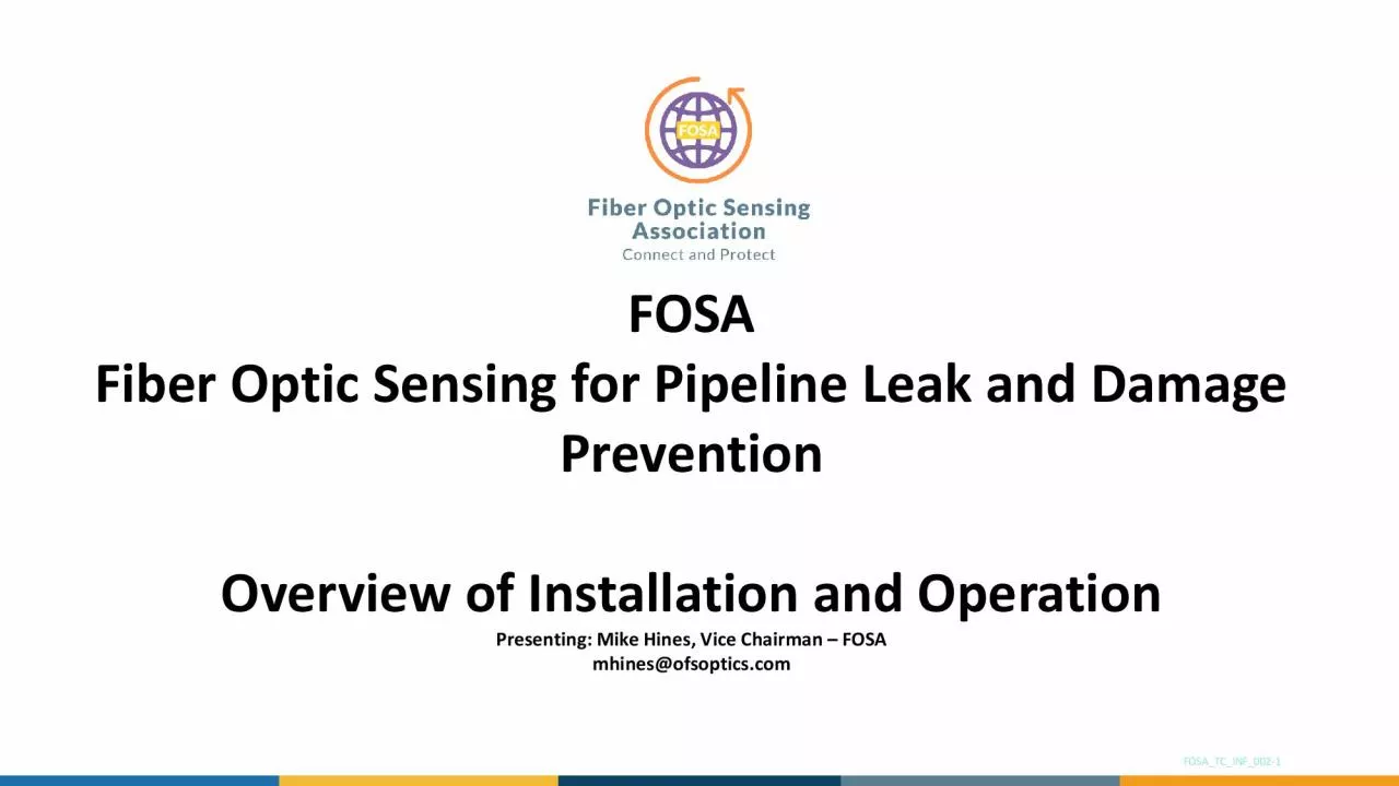
FOSA Prevention Overview of Installation and Operation Presenting Mike Hines Vice Chairman FOSA mhinesofsopticscom FOSATCINF002 1 What is FOSA The Fiber Optic Sensing Association ID: 820668

pipeline monitoring cable fiber monitoring pipeline fiber cable sensing leak detection strain optic pipe single conduit temperature buried vibration

Share:

Link:

Embed:

Download Presentation from below link

Download Pdf The PPT/PDF document "Fiber Optic Sensing for Pipeline Leak an..." is the property of its rightful owner. Permission is granted to download and print the materials on this web site for personal, non-commercial use only, and to display it on your personal computer provided you do not modify the materials and that you retain all copyright notices contained in the materials. By downloading content from our website, you accept the terms of this agreement.


Presentation Transcript

FOSAFiber Optic Sensing for Pipeline Le
FOSAFiber Optic Sensing for Pipeline Leak and Damage PreventionOverview of Installation and OperationPresenting: Mike Hines, Vice Chairman –FOSAmhines@ofsoptics.comFOSA_TC_INF_002-1What is FOSA? •The Fiber Optic Sensing Association (“FOSA”) is a non-profit industry association formed in 2017 in Washington D.C.•Provides North American education on the benefits of distributed fiber optic sensing technology, including through:•Webinars•Videos•White papers•Developing s

tandardized industry practices•Publi
tandardized industry practices•Public policy advocacy•Membership is open to companies globally who make, install, support and use distributed/quasi-distributed fiber optic sensors.FOSA MembersFiber Optic Sensing ApplicationsPipeline Condition MonitoringThird Party Intrusion/SecurityPipeline HeatTrace MonitoringGeo-TechnicsTransport MonitoringOil & Gas In-Well MonitoringStructural Health MonitoringIndustrial Process MonitoringPower Cable MonitoringKey benefits / safety appl

ications•Reliable–Ruggedized int
ications•Reliable–Ruggedized interrogator, simple fiber optic sensing cable, little to go wrong•Safe–passive sensor along pipeline, often dielectric, electricity only used at interrogator point / block valves•Secure–buried, affixed, or aerially installed, tampering is immediately evident•Economical–cost per sensing location is lowest on market, single fiber becomes thousands of sensing points•Scalable–multiple technologies or applications on a single cablePipeline Cond

ition MonitoringPipeline ROW Monitorin
ition MonitoringPipeline ROW MonitoringPipeline Geo-TechnicsPipeline Process MonitoringStructural Health MonitoringPipeline Heat Trace MonitoringSingle Phase DetectionMixed Phase Leak DetectionSubsea Leak DetectionPipeline ROW IntrusionHot Tap Theft PreventionValve (Theft) DetectionPerimeter securitySubsea Pipeline MonitoringEarthquake DetectionSoil Erosion MonitoringSubsidence MonitoringLand Slide MonitoringSlack line monitoringSlug ProfilingPig trackingPipeline Deformation / Hoo

p StrainPipeline Heat Trace Monitorin
p StrainPipeline Heat Trace MonitoringIntroductionDistributed FiberOptic Sensing (DFOS)Installation ConsiderationsUse CasesWhat is Distributed Fiber Optic Sensing? •Passive sensor: No power along asset•Monitors temperature, strain and/or vibration•Multiple applications possible in a single system•Upgradeable technology -without replacing sensor •Monitoring of fiber optic cables from a single location via pulsed laser light•24/7 Continuous Monitoring –over long continu

ous distances•1,000’s of sensing
ous distances•1,000’s of sensing points –high resolution with meter size localization potentialTemperatureVibrationStrainSignals extractable from a fiberOpticalAmplifierOpticalDetectorPulse of coherentlightDTSMechanism: Raman BackscatterSignal: Thermally Excited MoleculesResponds to: HeatMechanism: Brillouin BackscatterSignal: Thermally Excited VibrationsResponds to: Heat, StrainDSSMechanism: Rayleigh BackscatterSignal: Refractive Index changes Responds to: Vibration

, Heat, StrainDASBrillouin based DTS /
, Heat, StrainDASBrillouin based DTS / DSS is often combined in a single DSTS deviceNote: shown figuratively –separate fibers / devices required for each techniqueHow Does It Work? –general conceptThe phenomenon used to measure vibration, temperature or strain in a fiber optic cable relies on the interaction between a laser light and the glass in an optical fiber.When light travels through a transparent media, the main pulse travels forwards, but a small fraction is back-scattered throug

h interaction with the glass. This chan
h interaction with the glass. This changes at every point along the cable in accordance with the local environment.Different backscatter processes can be used to extract relevant information.That backscatter signal can be exploited by different technologies to understand the external environment–strain, temperature, vibration, etc.The end data can be used to understand the environment at every point along the fiber and act on the information.What are the Benefits?•Long reach –spans great

er than 50 miles (80 km) possible•Qu
er than 50 miles (80 km) possible•Quick scan –entire length scanned in seconds –real time reporting•High spatial resolution –thousands of sensing points, detect every few feet•Precise event location detection –know quickly and accurately when problems occur•All dielectric –centrally powered, no risk of sparking•Almost zero maintenance•Add additional fiber to the sensor cable –built-in communications capability along rights-of-way / broadband delivery

Per sensing point, there is no more ec
Per sensing point, there is no more economical way to monitor lengthy, critical assetsSelection of an appropriate cable Single Jacket (All-dielectric)Double Jacket (All-dielectric)Single Steel Tape Armor With one or two PE jacketsIn ConduitIn Conduit(or Direct Buried)Direct BuriedTight Buffer Cable, shown as tactical cable (top) and Distribution unit (below)2-5mm10-20 mm10-20 mm10-20 mm8-16 mmSpecial Application(direct buried / conduit)Fibertypes also influence the appl

ication but are largely choices of varie
ication but are largely choices of varieties of Single Mode (in long haul and general formats) or short haul Multi Mode. Raman DTS devices ONLY work on Multi Mode fibersGeneral Backbone Cable -BuriedGeneral Backbone Cable -ConduitOptimizing the position for various techniquesDAS / Acoustic / Vibration Sensing•Optimum location for ROW Monitoring –upper half of pipeline, 0.5-1.0m below surface•Optimum location for leak –minimum offset from pipe 0.3-0.5m•Similar for armor

ed/ ducted cable•Sand screening to
ed/ ducted cable•Sand screening to protect cableDSS / Strain Sensing•Strain measurement delivered WHERE the fiberis:•n soil close to pipe (~1m) –picks up soil strain•at pipe bottom picks up soil sagging / lift•strapped to pipe picks up strain coupled to pipeDTS / Temperature Sensing•Liquid leak applications –at pipe bottom (gravity spill) –15-30cm•Gas leak applications –above pipe (Joule Thompson cooling) –15-30cm•Trace Heat Monitoring –strapp

ed to pipe / heating elementGetting th
ed to pipe / heating elementGetting the fiberin the same trenchUtility Products MagazineFERC–Direct Buried Cable•Armored cable placed directly into the pipe trench, e.g. partially backfill, place cable –complete backfill•Good coupling and position orientation•Pauses to pipeline operation for splicing operation –cable in ~5-10km reels–Cable In Conduit•HDPE Conduit placed directly into the pipe trench, e.g. partially backfill, place conduit –complete backfill•

Unarmored Cable blown through conduit on
Unarmored Cable blown through conduit once backfill complete•Less disturbance to pipeline lay•Less well coupled but compensated for by lack of armor•Not suited to all measurement types (retards temperature measurement)–Retrofit•Currently in R&D with industry and government funding•Being addressed by both Government and Industrial R&D fundingLeak Detection•Some/insipient leaks are associated with abnormal local temperature changes•Detection limit 0.1% of flow –order of m

agnitude better than conventional CPM or
agnitude better than conventional CPM or Mass/Volume balance systems)•Thermal leak shows “signature pattern” that can be distinguished from surrounding conditions•Independent from leak size•Dedicated alarming algorithm provides efficient leak detection•Example: Controlled Methane leak•800 µm pinhole size•2.5bar gas pressure•Alarming•~15h after leak•7°C measured DTCopyright AP Sensing GMbH, published with permissionPipeline and facility securityDistance along

assetTime•Whether through theft or
assetTime•Whether through theft or accidental damage, fiber optic sensing monitors 24/7 and protects in real time. •In this example, illegal valve activity was observed –the data shows the sudden pressure pulse caused by the valve being opened•1stnight –system alerts to operation of illegal valve (not one known to client) and identifies approximate position –activity repeated 5 times –each corresponding to ~1 tanker load•Client heads to approximate location and is gui

ded in by system to location with 10m a
ded in by system to location with 10m accuracyCopyright OptaSense Ltd, published with permissionRockfall and landslide detection•Persisten rain within a canyon initiated a land slide that caused the track to be damaged•Multiple landslide alarms were raised from the DAS system to the dispatcher and were announced over the voice radio10 minutesLarge SlideCopyright OptaSense Ltd, published with permissionIndividually Configured ZonesNIGHT TIME THREAT ALERTS ON VEHICLES IN HIGH RISK AREA

SRIGHT OF WAY THREAT DETECTION EVERYW
SRIGHT OF WAY THREAT DETECTION EVERYWHEREBURIED PERIMETER SECURITY AT BLOCK VALVE FACILITYLEAK DETECTION EVERYWHEREFENCE SECURITYAT FACILITYINDUSTRIAL SITEPIG TRACKINGENABLED EVERYWHEREPIPELINELEAKCONSOLEPIPELINESECURITYCONSOLEPIPELINEOPERATIONSCONSOLETake-aways•Sense strain, temperature and/or vibration (acoustics) over spans exceeding 80 km (~50 miles) for each interrogator•DSS, DTS, DAS, DSTS•Non-invasive –install alongside or on pipe –method dependent•Di

stributed detection –spatial resolut
stributed detection –spatial resolutions of 10 meters (~33 feet)•Less than 1 meter (~ 3 feet) is also common•Detect gas leaks, liquid leaks, third-party intrusion (vehicles, footsteps, hand-digging, excavation, hot-tapping)•Complements aspirations to create “zero incident” pipelines•Proven technologies -worldwideFollow our activity on LinkedinVisit our website www.fiberopticsensing.orgContacts:Mike Hines -mhines@ofsoptics.comJoy Molony -jmolony@fiberopticsensing.org