/
TERA  Foundation on  behalf TERA  Foundation on  behalf

TERA Foundation on behalf - PowerPoint Presentation

everfashion
everfashion . @everfashion
Follow
345 views
Uploaded On 2020-08-04

TERA Foundation on behalf - PPT Presentation

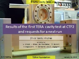
of U Amaldi J Bilbao de Mendizábal R Bonomi A Degiovanni M Garlasché and P Magagnin Silvia Verdú Andrés 3 GHz Cavity Test Results of the first TERA ID: 798113

test high tera bdr high test bdr tera field gradient linac pulse power cell coupled ghz cavity limit breakdown

Share:

Link:

Embed:

Download Presentation from below link

Download The PPT/PDF document "TERA Foundation on behalf" is the property of its rightful owner. Permission is granted to download and print the materials on this web site for personal, non-commercial use only, and to display it on your personal computer provided you do not modify the materials and that you retain all copyright notices contained in the materials. By downloading content from our website, you accept the terms of this agreement.


Presentation Transcript

Slide1

TERA

Foundation

on behalf ofU. Amaldi, J. Bilbao de Mendizábal, R. Bonomi, A. Degiovanni, M. Garlasché and P. Magagnin

Silvia Verdú Andrés

3 GHz Cavity Test

Results of the first TERA cavity test at CTF2and requests for a next run

1

CLIC meeting

January

13, 2012

Slide2

Motivation – TERA activities

The hadrontherapy community demands compact, reliable accelerators with the appropriate beam performances for tumour treatment with ions.

Slide3

TERA’s

proposal:cyclotron + high-freq. linac = cyclinacSilvia Verdú-Andrés

CELL COUPLED LINACCell Coupled Linac RF frequency: 5.7 GHz18 accelerating modules - Length of each module ~ 1.3 mHigh gradient

: 40 MV/m (TERA+CLIC collaboration)Cell Coupled Linac Standing-wave structureRF frequency:

5.7 GHz2.5 ms-long pulse at 300 Hz

3(CArbon BOoster for Therapy in Oncology)CABOTO

Slide4

C-band linac

Section 1cyclotronBeam dose deliveryRF rotating joints

Line with 2% momentum acceptanceC-band linac Section 2

RF Power sourcesW0W1W2

SM1SM2

TULIP(TUrning LInac for Protontherapy)

Cell Coupled Linac

Standing-wave structure

RF frequency:

5.7

GHz

2.5

m

s

-long pulse at

100 Hz

TERA’s

proposal

:

cyclotron +

high

-

freq

.

linac

=

cyclinac

Slide5

Motivation – TERA activities

The hadrontherapy community demands a compact, reliable accelerators with the appropriate beam performances for tumour treatment with ions.

Active energy modulationHigh repetition rate:

3D spot-scanning technique with multipainting+3D

feedback systemmoving organs treatment

+

CABOTO – 300 Hz

TULIP

TULIP – 100 Hz

Slide6

Hadron

therapy: the basicsCharged hadron beam that loses energy in matter

27 cmTumourtarget 200 MeV - 1 nA protons

4800 MeV – 0.1 nA carbon ions(radioresistant tumours)

Courtesy of PSISilvia Verdú-Andrés

tailhttt://global.mitsubishielectric.com/bu/particlebeam/index_b.html

6

Depth-dose

distribution

Slide7

Treating moving

organs requires...Silvia Verdú-Andrés7 Fast Cycling machine

(high repetition rate ~ 200-300 Hz)Tumour MULTIPAINTING

Fast Active Energy Modulation (a couple of ms)

Fast 3D correction of beam spot position in depth

Single ‘spot’ pencil beam Lateral scanning with magnets: 2 ms/step3D conformal treatment

Depth scanning: ACTIVE ENERGY MODULATION

Slide8

TERA’s

proposal:cyclotron + high-freq. linac = cyclinacSilvia Verdú-Andrés

CELL COUPLED LINACCell Coupled Linac RF frequency: 5.7 GHz18 accelerating modules - Length of each module ~ 1.3 mHigh gradient

: 40 MV/m (TERA+CLIC collaboration)Cell Coupled Linac Standing-wave structureRF frequency:

5.7 GHz2.5ms-long pulse at 300 Hz

8(CArbon BOoster for Therapy in Oncology)CABOTO

Slide9

TERA’s

proposal:cyclotron + high-freq. linac = cyclinac

120MeV/u

400MeV/uSilvia Verdú-Andrés

CELL COUPLED LINACCell Coupled Linac

RF frequency: 5.7 GHz18 accelerating modules - Length of each module ~ 1.3 mHigh gradient : 40 MV/m (TERA+CLIC collaboration)Cell Coupled Linac Standing-wave structureRF frequency: 5.7 GHz9(CArbon BOoster for Therapy in Oncology)

CABOTO

Higher

accelerating

gradients

Reduce

size and

cost

!

Slide10

TERA’s

proposal:cyclotron + high-freq. linac = cyclinac

120MeV/u

400MeV/uSilvia Verdú-Andrés

CELL COUPLED LINACCell Coupled Linac RF frequency: 5.7 GHz

18 accelerating modules - Length of each module ~ 1.3 mHigh gradient : 40 MV/m (TERA+CLIC collaboration)Cell Coupled Linac Standing-wave structureRF frequency: 5.7 GHz10(CArbon BOoster for Therapy in Oncology)

CABOTO

Higher

accelerating

gradients

Reduce

size and

cost

!

Common

goals

for

TERA and CLIC

Cell

shape

E

S

/E

0

E

0

[MV/m]

E

s

max

[MV/m]

BDR

required

[

bpp

/m]

TERA

linacs

4

5

35

40

200

10

-6

(

reliability

)

CLIC

structures

2

100

200

10

-6

Slide11

Operation limit for S-band cavities  BreakDown Rate BDR limit described by surface field ES (Kilp.) mod. Poynting vector SC

Scaling laws (ES, SC, pulse length, temperature, frequency)evaluated for X, K and C bands Applying found limit to future designs ensure reliable operation optimize RF structures (efficiency, length, cost

) TERA high-gradient single-cells test program Our interests

Slide12

3 GHz

One prototypePreliminary high-power test in 2010. High power in 2011.TERA High Gradient Test Program

5.7 GHz3 prototypes for testing:- BDR behaviour,- eventual hot spots for BD activity

- BD as function of machining procedure (i.e conventional vs. diamond turning)Under tuning and brazingHigh power test of high-gradient performance single-cell cavities at two different frequencies

:

Slide13

3 GHz test:

prototype layout Single accelerating cell (two unsymmetrical half cells) H-coupled to WR284 waveguide.

Two lateral plates for structure cooling. CF flanges for data acquisition .Cell Parameters

Material

C10100 Copper

Dimensional tolerance band20 μmSurface roughness (Ra) 0.4 μm

Slide14

3 GHz test:

prototype productionBrazing (Bodycote, France) :

Machining (VECA, Italy):

Slide15

Preliminary T

est – February 2010 at CTF3CLIC collaboration in low power measurements and preliminary high-power testing at CTF3 in February 2010

Breakdown identification from Faraday Cup signal

BD event

Slide16

Gradient limitations for high frequency accelerators,

S. Döbert, SLAC, Menlo Park, CA 94025, USA (2004)Limit in copper to surface field by breakdown surface damage

TERAPreliminary T

est – February 2010 at CTF3… and the cavity was stored under nitrogen for

more than one year until September 2011.

Slide17

Test September 2011

Slide18

Experimental Set-up

at CLIC Test Facility (CERN)Rf circuit: klystron no.30, 3 GHz, 5 Hz, 50 MW peak power

Vacuum station (ion pump): 10-8 mbarCooling system

: thermalized water (30°C), constant water flow (5L/min)Diagnostics:Faraday cupIncident and

reflected RF power (amplitudes and phases)Vacuum gaugeTemperature of cavity and coolant (thermistors and Pt100, respectively)

Remote control of the incident RF pulse performacesAutomatic data acquisition system

Slide19

RF

windowbidirectional couplertowards 3 GHz TERA single-cell cavityvacuum systemfrom klystron 30

from

klystron 30

3 GHz TERA single-cell cavity

Slide20

from

klystron 303 GHz TERA single-cell cavity

from klystron 30

cavityvacuum portaside Faraday cup

vacuum portupstream cavity vacuum lecture

Faraday cupvacuum portaside Faraday cupFaraday cup

cavity

Slide21

from

klystron 30cooling system PT100 thermistors

PT100

in

in

outout

Slide22

Experiment timeline

About 250 RF hours (total: ~ 106 seconds), equal to 4.5 million RF pulses which led to more than 3000 breakdowns used to condition 1 dm2 of copper surface. (*) No availability to supervise test so

run at low field (interesting for TERA applications)(+) Scaling laws evaluation

Circulator installation

ES = 350 MV/m

Slide23

Circulator installed to avoid interference of the power reflected by the cavity with the incident RF pulse. Lwaveguide is 76 m vgroup is 0.72cTherefore, signal reflection expected

at 0.7 ms.Incident RF pulse (no circulator)Incident RF pulse (circulator)

Slide24

Experiment

timeline-- evolution of electric field

with RF-on time --

max

maxGradient limitations for high frequency accelerators, S. Döbert, SLAC, Menlo Park, CA 94025, USA (2004)

TERA

Slide25

p

ulse length

incident RF pulse

estimated reflected RF pulse« dynamic » stored energymeasured reflected RF pulse

RF pulse characteristics

-- Normal operation --(12-20% of power in  b ~0.9)field emission current signal

(< 8 mA

peak

within

2.5

m

s-

long

pulse)

n

egative

current

:

electrons

!

Slide26

p

ulse length

i

ncident RF pulseestimated reflected RF pulse« dynamic » stored energymeasured reflected RF pulse

RF pulse characteristics

-- Normal operation --(12-20% of power in  b ~0.9)-- Breakdown --

f

ield emission current signal

(< 8

m

A

peak

within

2.5

m

s-

long

pulse)

n

egative

current

:

electrons

!

a)

reflected

power

increase

:

b

)

field-emission

current

burst

:

b

reakdown

!

0

0

electrons

p

ositive

ions

Slide27

Breakdowns which do not lead to a field recovery.

Breakdowns which lead to a field recovery.

Slide28

RF pulse characteristics

-- Accelerating gradient evaluation --

Slide29

Conditioning

-- accumulated breakdowns with RF-on time --

About 250 RF hours (total: ~ 106 seconds), equal to 4.5 million RF pulses which led to more than 3000 breakdowns used to condition 1 dm

2 of copper surface.

Slide30

The field enhancement factor

b after “conditioning” is about 40 (assuming f = 4.5 V). Conditioning-- field enhancement factor b

--

Slide31

higher field

higher current / field

 worse performanceConditioning-- field enhancement

factor b with time --

Slide32

BDR

measurements of the last 2 days of the test-- Compared to measurements in 2010 --

0bd, 8.3h

6bd, 4.6h22bd, 1.5h1bd, 5.6h

Slide33

BDR

measurements of the last 2 days of the test

-- Breakdowns identified from FE current burst

or reflected RF energy --

Slide34

--

field emission

current burst OR

reflected RF energy

?--

The number of breakdowns identified by a field-emission current burst is extremely sensitive (1 order of magnitude) to the threshold used to

define a breakdown

event from

this

signal

.

Next

test:

use

photomultipliers

to

detect

breakdowns

from

light

emission

.

Slide35

BDR

measurements of the last 2

days of the test-- scaling laws: BDR

EXtPY --

  2.2 ms

1.5 ms1.0 msBDR E13 BDR E23


BDR

t

P

1.2


Slide36

BDR

measurements of the last 2

days of the testScaling laws

:BDR  E1321 tP1.6

Slide37

Operation

limit to high gradient performance-- Modified Poynting vector Sc

power law--A. Grudiev, S. Calatroni, and W. Wuensch, “New local field quantity describing the high gradient limit of accelerating structures”. Phys. Rev. ST

Accel. Beams 12, 102001 (2009): http://prst-ab.aps.org/pdf/PRSTAB/v12/i10/e102001The square root of SC has been scaled to tpulse= 200ns and BDR = 10

-6bbp/mX-band TWS X-band SWS 30 GHz

TWS

Slide38

Operation

limit to high gradient performance-- Modified Poynting vector Sc

power law--

A. Grudiev, S. Calatroni, and W. Wuensch, “New local field quantity describing the high gradient limit of accelerating structures”. Phys. Rev. ST Accel. Beams 12, 102001 (2009): http://prst-ab.aps.org/pdf/PRSTAB/v12/i10/e102001The square root of SC has been scaled to

tpulse= 200ns and BDR = 10-6bbp/mDESIGN

Slide39

Operation

limit to high gradient performance

-- Stress model exponential

law--

F. Djurabekova et al., “Multiscale modeling of electrical breakdown at high electric fields”. Talk in the International workshop on Mechanisms of Vacuum Arcs MeVArc, Helsinki, Finland (2011): http://beam.acclab.helsinki.fi/hip/mevarc11/presentations/djurabekova.pdf

Defect volume DV [m3]Dislocation loop radius rloop [nm]Other experimental data[0.8,13]*10-25[13,40]BDR exp (E2)


Slide40

TERA 3 GHz SCC Test

2.9*10-2521

Operation limit to high gradient performance

-- Stress model

exponential law--

F. Djurabekova et al., “Multiscale modeling of electrical breakdown at high electric fields”. Talk in the International workshop on Mechanisms of Vacuum Arcs MeVArc, Helsinki, Finland (2011): http://beam.acclab.helsinki.fi/hip/mevarc11/presentations/djurabekova.pdf Defect volume DV [m3]Dislocation loop radius rloop [nm]

Other experimental data

[0.8,13]*10-25[13,40]

Test

results

are

consistent

with

other

experimental data

BDR

exp

(E

2

)


Slide41

TERA 3 GHz SCC Test

2.9*10-2521

Operation limit to high gradient performance

-- Stress model

exponential law--

F. Djurabekova et al., “Multiscale modeling of electrical breakdown at high electric fields”. Talk in the International workshop on Mechanisms of Vacuum Arcs MeVArc, Helsinki, Finland (2011): http://beam.acclab.helsinki.fi/hip/mevarc11/presentations/djurabekova.pdf Defect volume DV [m3]Dislocation loop radius rloop [nm]

Other experimental data

[0.8,13]*10-25[13,40]

Test

results

are

consistent

with

other

experimental data

BDR

exp

(E

2

)


interest

Slide42

Breakdown

Timing within RF pulse

450 kW,

ES= 265MV/m, t

p = 2.2 ms6 events

600 kW, tp = 1.0 ms12 events 600 kW, ES=325MV/m, tp = 2.2 ms22 events450 kW, ES= 265MV/m, tp = 2.2 ms1 event

Slide43

Hadrontherapy

application: ES = 140--175 MV/m with tflat-top = 2.2

ms BDR < 10-6 bpp/m (requirement)Consequences for TERA

Cavity

tests:

ES = 265 MV/m with tflat-top = 2.2 msBDRmeasured (reflected RF energy) =5·10-4bpp/m

Slide44

Hadrontherapy

application: ES = 140--175 MV/m with tflat-top = 2.2

ms BDR < 10-6 bpp/m (requirement)Consequences for TERA

Cavity

tests:

ES = 265 MV/m with tflat-top = 2.2 msBDRmeasured (reflected RF energy) =5·10-4bpp/mBDR measurement at ES = 140--175 MV/m with tflat-top = 2.2 ms is important for TERA applications,

no need to apply

scaling laws.

Slide45

Hadrontherapy

application: ES = 140--175 MV/m with tflat-top = 2.2 ms BDR < 10-6

bpp/m (requirement)Consequences for TERA

Assuming that scaling law BDR EX applies: 

X=20  BDR ~ 10-9 -- 10-7 bpp/mX=10  BDR ~ 10-6 -- 10

-5 bpp/mFor operation at 100 Hz: XTime/event1017 hours156 days201.5 months!

Cavity

tests:

E

S

= 265 MV/m

with

t

flat

-top

= 2.2

m

s

BDR

measured

(

reflected

RF

energy

)

=5·10

-4

bpp/m

BDR

measurement

at

E

S

= 140--175 MV/m

with

t

flat

-top

= 2.2

m

s

is

important for TERA applications,

no

need

to

apply

scaling

laws

.

Slide46

Strategy

for February 2012-- dreamed scenario --

Testing time: 17 daysSchedule:Start + continue conditioning (1+2 days)BDR

measurements at high field interesting for CLIC comparison (2-3 days, scaling law evaluation)BDR measurement

at low field interesting for TERA applications (12 days)* Dark current measurements at different stages

Slide47

Summary

and ConclusionsDebugged Control and Data Acquisition Systems More diagnostic intrumentation includedSome conditioningFirst interesting measurements of

field enhancement factor and breakdown rate, and evaluation of scaling lawsHowever,Conditioning process

has not been completed yet: 3 daysComparison with scaling laws used by CLIC: 2-3 days

BDR measurement at TERA field: 10-12 days at 100 Hz

Slide48

Test

February 2012

Lessons learned from the latest test To do list before the

next test Strategy for next test

Slide49

Comments for the next test--

lessons learned from this experience--Use photomultipliers to detect breakdowns from light emission.Be careful with saturated signals.Measure dark current for field enhancement factor calculation before conditioning starts. Connect ALL signals to the same data acquisition system to ease synchronization.

Slide50

Conclusions

We are happy, we are grateful and we would like more testing time (it would make us much happier and much more grateful!).

Slide51

Acknowledgements

We would like to express our gratitude to the CTF3 group for permission to run experiment in their test facility and technical and scientific support (Gerry McMonagle, Jan Kovermann, Roberto Corsini, Stephane Curt, Stephane Rey, Frank Tecker, Esa Paju, Ghislain Rossat, Wilfrid Farabolini, Thibaut Lefevre, Aurelie Rabiller, etc.) to prepare and perform the experiment. We also acknowledge the CLIC RF structure development group (Walter Wuensch, Igor Syratchev, Alexej Grudiev, Jiaru Shi, etc.) for the enriching discussions about the preparation, development and analysis of the test. We are also grateful to Rolf Wegner, who leaded the design, prototyping and first high-power test of the cavity, for his valuable discussions on the continuation of the high power tests. Special thanks go to

Alexey Dubrovskiy and Luca Timeo, for their special involvement in the experiment. We also acknowledge Javier Bilbao de Mendizábal and Paolo Magagnin for their precious time spent in long shifts and Eugenio Bonomi for the support on the temperature measurement system preparation. Thanks to Vodafone Italy foundation for the fundings received to produce the test cavity. Thanks also to the CERN PS group and CERN General Services for the technical support.

Slide52

[Degiovanni et al.] A. Degiovanni et al., « TERA High Gradient Test Program of RF Cavities for Medical Linear Accelerators ». NIM A 657 (2011) 55-58:

http://www.sciencedirect.com/science?_ob=MiamiImageURL&_cid=271580&_user=107896&_pii=S0168900211008886&_check=y&_origin=&_coverDate=21-Nov-2011&view=c&wchp=dGLzVlk-zSkWz&md5=401347aa3fed9fd2706dc8d36b049a94/1-s2.0-S0168900211008886-main.pdf[Wang&Loew] J. W. Wang and G. A. Loew, “Field Emission and RF Breakdown in High-Gradient Room-Temperature Linac Structures”. SLAC-PUB-7684 (1997): http://slac.stanford.edu/cgi-wrap/getdoc/slac-pub-7684.pdf  [Grudiev et al.] A. Grudiev, S. Calatroni, and W. Wuensch, “New local field quantity describing the high gradient limit of accelerating structures”. Phys. Rev. ST Accel. Beams 12, 102001 (2009): http://prst-ab.aps.org/pdf/PRSTAB/v12/i10/e102001[Djurabekova at al.] F. Djurabekova et al., “Multiscale

modeling of electrical breakdown at high electric fields”. Talk in the International workshop on Mechanisms of Vacuum Arcs MeVArc, Helsinki, Finland (2011): http://beam.acclab.helsinki.fi/hip/mevarc11/presentations/djurabekova.pdf Bibliography