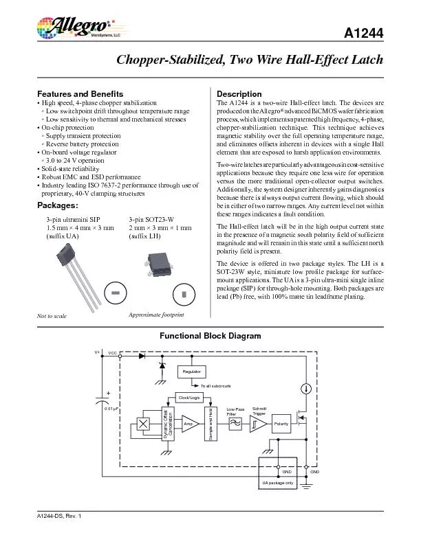
PDF-The A1244 is a two-wire Hall-effect latch. The devices are produced on
Author : giovanna-bartolotta | Published Date : 2016-02-29
Amp RegulaTo all subcircuitsTriggerLowPassFilter VCC UA package only 001 ClockLogicDynamic OffsetCancellationSample and Hold Approximate footprintsuffix LHsuffix
Presentation Embed Code
Download Presentation
Download Presentation The PPT/PDF document "The A1244 is a two-wire Hall-effect latc..." is the property of its rightful owner. Permission is granted to download and print the materials on this website for personal, non-commercial use only, and to display it on your personal computer provided you do not modify the materials and that you retain all copyright notices contained in the materials. By downloading content from our website, you accept the terms of this agreement.
The A1244 is a two-wire Hall-effect latch. The devices are produced on: Transcript
Amp RegulaTo all subcircuitsTriggerLowPassFilter VCC UA package only 001 ClockLogicDynamic OffsetCancellationSample and Hold Approximate footprintsuffix LHsuffix UA ChopperStabilized Two Wir. The information you provide will be shared with third parties to the extent necessary to process the payment This includes sharing with the recipients bank any intermediary financial institutions involved in processing the payment and where required 9 Bipolar Power Devices Power devices can be classified into bipolar based devices MOSFET based devices and devices such as the IGBT that combine a bipolar transistor with a MOSFET Bipolar power devices are the tra For simplicity the control input C is not usually listed Again these tables dont indicate the positive edge triggered behavior of the flipflops that well be using brPage 21br brPage 22br brPage 23br Characteristic equations Characteristic equations S1 S1R1 never 11 R1 brPage 9br S1 Levelsensitive SR latch S1 Clk R1 brPage 10br 100 GHz 001 ns Period Freq 10 GHz 1 GHz 100 MH 01 ns 1 ns 10 ns 100 MH 10 MHz 10 ns 100 ns brPage 11br S1 Levelsensitive SR latch Clk R1 brPage 12br D latch DQ D latch – . An . RTL Approach to Asynchronous Design . Presentor. : Chi-. Chuan. Chuang. Date : 2012.12.20. O. utline. Introduction. C-element. Null convention logic (NCL) . NCL asynchronous systems . UNCLE synthesis flow. Michael McCraney. Southern Company Transmission System. Some pics to use. What is first trip testing? . Identifying lubrication problems in the mechanism.. Identifying mechanical wear.. Identifying control circuit malfunctions.. Sequential Circuits. Montek Singh. Sep 21, 2015. 2. Topics. Sequential Circuits. Latches. Flip Flops. Verilog . for sequential design. Example: A . simple counter. 3. Sequential Circuits. State. of system is . promon. Presented by:. Gus . Bjorklund. & Dan Foreman. And how it may help in troubleshooting certain DB problems. Gus . Bjorklund. Progress Wizard. Dan Foreman. Progress User since 1984. Author of several Progress related . Weisong. . Tu. Department of Physics and Astronomy. University of Tennessee. Instructor: Dr. . George . Siopsis. Introduction. Quantum Hall Effect. The quantum Hall effect is a quantum-mechanical version of the Hall effect, observed in two-dimensional electron systems subjected to low temperatures and strong magnetic fields. In the quantum hall effect, and the conductivity can be represented as. CS345. David . Monismith. Based upon notes by Dr. Bill . Siever. and notes from the . Patternson. and Hennessy Text. Recall. Recall that the RS-Latch allows for storage of a single bit through the use of either . Latches, Flip-Flops and Decoders. Sequential Circuit. What does this do?. The OUTPUT of a sequential circuit is determined by the current output values from a previous operation.. . In other words the output is a part of the input. . Prof. Kavita Bala and Prof. Hakim Weatherspoon. CS 3410, . Spring 2014. Computer Science. Cornell University. See P&H Appendix . B.7. . . B.8. , . B.10. , . B.11 . Stateful. . Components. Until now is combinatorial logic. and . Flip-Flops. Jack . Ou. , Ph.D. .. Sequential Circuits. New output are dependent on the inputs and the preceding values of outputs.. Characteristic: output nodes are intentionally connected back to inputs.. Recap. The. forward bias. reduces the potential barrier of the diode and establishes the easy path for the flow of current. . While in . reverse bias. the potential difference increases the strength of the barrier which prevents the charge carrier to move across the junction. .
Download Document
Here is the link to download the presentation.
"The A1244 is a two-wire Hall-effect latch. The devices are produced on"The content belongs to its owner. You may download and print it for personal use, without modification, and keep all copyright notices. By downloading, you agree to these terms.
Related Documents