/
Hybrid Controller Chip (HCC) Hybrid Controller Chip (HCC)

Hybrid Controller Chip (HCC) - PowerPoint Presentation

hoodrona
hoodrona . @hoodrona
Follow
347 views
Uploaded On 2020-08-05

Hybrid Controller Chip (HCC) - PPT Presentation

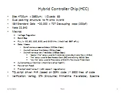
Size 4700um x 2860um IO pads 83 Dual padring structure to fit onto Hybrid IBM Standard Cells 20000 727 Decoupling caps 200pF Nets 22942 Macros Voltage Regulator Band Gap PLL w 40 80 160 320 and 640MHz Modified GBT ID: 799078

mhz delay 160 fine delay mhz fine 160 pio data hybrid coarse epll macro clock stave drv160 640mhz liberty

Share:

Link:

Embed:

Download Presentation from below link

Download The PPT/PDF document "Hybrid Controller Chip (HCC)" is the property of its rightful owner. Permission is granted to download and print the materials on this web site for personal, non-commercial use only, and to display it on your personal computer provided you do not modify the materials and that you retain all copyright notices contained in the materials. By downloading content from our website, you accept the terms of this agreement.


Presentation Transcript

Slide1

Hybrid Controller Chip (HCC)

Size: 4700um x 2860um; I/O pads: 83Dual pad-ring structure to fit onto HybridIBM Standard Cells: ~20,000 + 727 Decoupling caps (200pF)Nets: 22,942Macros:Voltage RegulatorBand GapPLL /w 40, 80, 160, 320, and 640MHz (Modified GBT ePLL)Delay Macos: Synchronous coarse delays (6.25ns steps )Asynchronous fine delays (0.6ns steps)Asynchronous very fine delay (200ps steps)“Coarse + fine” delays used for Hybrid-side signals (BC_Hybrid, R3sL1, CMDL0)“fine” delays used for Data Readout Clock (DRC) and returning ABC130 Data “Very fine” delay used for Phase delay of 640MHz Fast Cluster Finder ClockAutonomous Monitor (monitors chip health)Power-on ResetPrompt event circuit (USA export regulations)TCL script driven PnR (based on CERN code ) ~ 3600 lines of codeVerification: Verilog, STA (Encounter, Primetime if available), Spectre

3/11/2014

Penn

1

Slide2

PnR Status

PnR Flow workingLVS clean OA (Virtuoso) databaseDRC nearly clean Some (~10-20) antenna violations , couple spacing.ECO flow to fixTiming violationsAnalysis of STA constraints continuingTestbench functional simulations ongoing Signal Integrity Violations (xtalk glitches)ECO flow to fix

Slide3

Liberty files and Constraints

Liberty file functions:Define timing arcs propagated through macrosDefine output signal transition rate modelDefine pin min/max output capacitances for modeling edge ratesDefine pin input max_transition rate (limit of tables)ePLL and AutonMon do not require one for timing purposes however:Still need Liberty file for output transition model and capacitances Can we use clock constraints instead?? (set_clock_transition, set_input_delay, etc)All input/output pads have liberty files to time arcs w.r.t. external signals (virtual external clock)Delay elements only need combinatorial logic delays defined when select lines are set to minimum. (created by encounter during macro PnR)Still missing Pre-emphasis driver Liberty file for GBT.

Slide4

Power/Ground connectionsSpectre simulation

Removed synthesized core logicKeep all macros (ePLL, Delay elements)Ramp up raw DVDD voltageWatch Regulator and Bandgap workSchematic sim after LVSNext, extracted netlist sim

Slide5

HCC Clock Domains:

BC_STAVE,

ePLL

f

A

,

ePLL

f

1, LOCAL40/80/160,

Fclk

BC

RCVR

L0_CMD Rcvr

COMMAND DECODER

BC_HYBRID

CMDL0_HYBRID

R3sL1_HYBRID

Rclk_HYBRID

*

Data

Concentrator

320MHz

X

Data

X

Data

X

Data

X

Data

Data

Drivers

320 MHz

BC_STAVE

GBT Inputs

R3_L1 Rcvr

R3sL1

Point-to -Point

Data to GBT

(8b/10b encoded)

Fine Delay

rst

Static/analog

3/12/2014

5

(80/160 MHz)

(40 MHz)

f

1

f

A

f

A

(80 MBS)

(80 MBS)

Trigger_gen_rst

(80/160 MHz)

(80/160 MHz)

(80/160 MHz)

(80/160 MHz)

* Clock speed options:

80 or 160 MHz

ePLL

REF IN

160MHz

320MHz

640MHz

Fclk

Coarse Delay

DIVIDE 2

(80 MHz)

Sel_Rclk

rst

4

Data in

Xoff out

(160 MHz)

(80/160 MHz)

80MHz

or

f1

MUX21BAL_L

Fine Delay

Coarse Delay

Fine Delay

Coarse Delay

2

dmux

dmux

R3

L1

L0

CMD

4

4

2

2

PIO_REC160

(NO hysteresis on clocks)

PIO_HYSTREC

PIO_DRV160

PIO_REC160

PIO_DRV160

PIO_HYSTREC

PIO_PRE_EMPH

PIO_DRV160

PIO_DRV160

PIO_DRV160

BCdelayC

<1:0>

BCdelayF

<3:0>

R3sL1delayC<1:0>

R3sL1delayF<3:0>

CMDL0delayC<1:0>

CMDL0delayF<3:0>

DataXdelayF

<3:0>

X = 1,2,3,4

4

4

4

4

MACRO

FDELAY

(

DelayLine

)

Fclk

640MHz

80 MHz

Sel_FCF

160 MHz

320 MHz

640 MHz

(

Fclk

)

4

FCFdelayC

<3:0>

MACRO

MACRO

MACRO

40MHz

160MHz (

f

1)

640MHz

Fine Delay

MACRO

Fine Delay

MACRO

Fine Delay

MACRO

Fine Delay

MACRO

320MHz (

f

A

)

Slide6

How to delay BC_HYBRID ?

(Coarse Delay using Shift register + Fine Delay using Delay Line)D

Q

D

Q

D

Q

D

Q

160 MHz

D

Q

N bit

MUX

Coarse Delay

ePLL

ref

BC_STAVE

40MHz

160MHz

Fine Delay

(16 Taps)

Asynchronous Fine Delay:

Min step size: 420

ps

(T=

-

30C)

Max step size: 830

ps

(T=55C)

Tap1

Tap2

Tap3

TapN

BC_HYBRID

40MHz

Coarse Delay

: Done with shift register driven by 160MHz clock.

6.25ns steps, (

NO RESET ISSUES

)

Fine Delay

: tapped delay chain

420 to 830

ps

PVT range; step size using 16-Tap Delay Line)

Here is how to avoid startup phase issues on BC_HYBRID clock:

Directly

delay

BC_STAVE

using shift register

ePLL

guantees

a known (programmable) relationship between

BC_STAVE

and

f1

Any jitter on

BC_STAVE

is eliminated when the (stable)

ePLL

f1

clock samples it.

f1

f1

6.25 ns /tap

Select Coarse Delay

Input

Output

Select fine Delay

4

3/12/2014

6

N=2 ? (4 Taps)