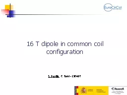
/
Magnetic and Mechanical Design of a 16 T Common Coil Dipole for FCC Magnetic and Mechanical Design of a 16 T Common Coil Dipole for FCC

Magnetic and Mechanical Design of a 16 T Common Coil Dipole for FCC - PowerPoint Presentation

joy
joy . @joy
Follow
65 views
Uploaded On 2023-11-12

Magnetic and Mechanical Design of a 16 T Common Coil Dipole for FCC - PPT Presentation

J Munilla F Toral CIEMAT Thanks to R Gupta BNL Q Xu IHEP T Salmi TUT and S IzquierdoBermúdez CERN for their suggestions and help FCC week Amsterdam April 10th ID: 1031509

coil coils design support coils coil support design stress main horizontal mpa pre common forces electromagnetic vertical lorentz field

Share:

Link:

Embed:

Download Presentation from below link

Download Presentation The PPT/PDF document "Magnetic and Mechanical Design of a 16 T..." is the property of its rightful owner. Permission is granted to download and print the materials on this web site for personal, non-commercial use only, and to display it on your personal computer provided you do not modify the materials and that you retain all copyright notices contained in the materials. By downloading content from our website, you accept the terms of this agreement.


Presentation Transcript

1. Magnetic and Mechanical Design of a 16 T Common Coil Dipole for FCCJ. Munilla, F. Toral - CIEMATThanks to R. Gupta (BNL), Q. Xu (IHEP), T. Salmi (TUT) and S. Izquierdo-Bermúdez (CERN) for their suggestions and helpFCC week, Amsterdam, April 10th, 2018

2. Outline2Introduction2-D electromagnetic design3-D electromagnetic design2-D mechanical designConclusion

3. 2-D magnetic results summary3Design #11 needs less superconductor, but has problems with peak voltages during quench.Design #11 needs more superconductor, but fulfils all requests with a well balanced design.Design #12 is even better, but cable fabrication is more challenging (Cu:Sc=0.8).Design #13 and #14 are valid for an upgrade of LHC (650 mm outer iron diameter). They need more superconductor, specially when reducing the intra-beam distance (which also reduces the fringe field).

4. Electromagnetic design: Design #124

5. Electromagnetic design: Design #125

6. Electromagnetic design: Design #126

7. 3-D electromagnetic design7Peak field at coil end is similar to cross section:The iron does not cover coil ends.The coils have different lengths and bending radii.The iron is shaped to decrease the variation of field harmonics with current (b3 and a2 below 5 units, the rest is negligible).Each coil end is 255 mm long. The coils are 14.5 m long to provide a magnetic length of 14.3 m.The internal splice in the high field coil can be done at the coil ends, where the field is low.

8. Outline8Introduction2-D electromagnetic design3-D electromagnetic design2-D mechanical designConclusion

9. Common Coil Dipole: Forces at coils9The forces per coil are similar for the block and common coil designs. In the case of the common coil, there is a vertical repulsive force between both apertures.

10. Common Coil Dipole: Support structure10The forces per quadrant are similar for the block and common coil designs. However, the external support structure needs to hold twice the force in the case of the common coil magnet.

11. Common Coil Dipole: Vertical pre-stress11In a block dipole, the shell can apply a direct vertical pre-stress on coils.In the common coil, most of the vertical pre-stress is lost because of vertical Lorentz forces and thermal contraction of support structure at the magnet mid-plane.

12. 2-D mechanical support12There are two possibilities to hold the large horizontal Lorentz forces:To let the main coils move and hold the pole coils with a cantilevered support. That is, a small coil pre-compression at cold.To pre-compress the main coils against a closed structure around the beam pipe, which also holds the pole coils.The first option needs less superconductor. When the main coils are shifted by 2.5 mm, the magnet needs 4% more cable and stores 10% more energy.

13. Open beam pipe support model13All the pieces are continuous at the other side of the symmetry axes.A 40 mm thick stainless steel shell holds the large horizontal Lorentz forces.The main coils are glued. They have copper spacers to perform equal height. Copper spacers and cable blocks are modeled as different materials.The pole coils are glued to a 0.5 mm thick aluminium foil. They are hold by stainless steel pieces, bolted to a vertical plate to constitute a casing around the main coils. Those screws hold partially the horizontal Lorentz forces.No bladders. Small radial gap for assembly.

14. 2-D FEM results: coil stresses14The stresses on the coils are moderate for a high field magnet at all the load steps: assembly, cool-down and energizing. It is the consequence of not using pre-compression.Assembly: Max 36 MPaCool down: Max 76 MPa16 T: Max 136 MPa

15. 2-D mechanical model results: displacements15The coils move quite uniformly about 0.5 mm in horizontal direction:The impact on field quality is moderate: 5.5 units on b3, 1 unit on b7, 0.8 on a2, less than 0.2 in the rest of multipoles.There is sliding between coils and casing, because friction under vertical force is not enough to hold the horizontal Lorentz force. The dissipation heat appears at the copper spacer, not at the cables surface.Less stored elastic energy without pre-compression.This model needs further investigation using a prototype.Horizontal (left) and vertical (right) displacements during energizing Horizontal displacements from assembly to nominal field

16. Coil deformation under Lorentz forces16JUST COILS: Horizontal movement is blocked at the iron interfaceHorizontal force: +14,5 MN/mVertical force: +0,6 MN/mHorizontal displacement: +0,23 mmVertical displacement: -0,13 / +0,14 mmX=0y=0

17. Closed beam pipe support model17An outer shell of stainless steel (70 mm) holds the horizontal Lorentz forces.Yoke is cut in 4 pieces. Invar to increase pre-stress. Magnetic simulation was made considering iron yoke, then changed to invar at structural analysis.Main coils are impregnated together, but NONE of them are bonded to supporting structure.Bladder and keys with large pressure.Friction coeffient of 0.2.

18. Coils X stress 18“azimuthal” stress for Ancillary coils“radial” stress for main coilsAssemblyPeaks +11/-71 MpaCool downPeaks +31/-202 MPa16 TPeaks +14/-146 MPaKeys inPeaks +9/-57 Mpa-120 MPa-28 MPa-35 MPa-25 MPaContact pressure

19. Coils Y stress 19“azimuthal” stress for Ancillary coils“radial” stress for main coilsAssemblyPeaks +1/-56 MpaCool downPeaks +48/-87 MPa16 TPeaks +11/-133 MPaKeys inPeaks +4/-37 Mpa

20. Closed beam pipe support model with limited pre-stress20An outer shell of stainless steel (80 mm) holds the horizontal Lorentz forces.Yoke is cut in 4 pieces. Invar to increase pre-stress only at magnet mid-plane. No bladders.Coils are not bonded to support structure. Intermediate supports in between the main coils to change the stress distribution.Friction coeffient of 0.2.

21. Results: Vertical StressAssemblyCold16 TLess than +10 Mpa for local tensile stress values

22. Summary of mechanical results22OPEN SUPPORT (16T)Displ. X COILS (mm)0,58 / 0,40Displ. Y COILS (mm)0,03 / -0,23σVM Support (MPa)527CLOSED SUPPORT (KEYS) (16T)Displ. X COILS (mm)0,275 / 0,11Displ. Y COILS (mm)0,05 / -0,25σVM Support (MPa)1059CLOSED SUPPORT (LIMITED PRELOAD) (16T)Displ. X COILS (mm)0,42 / 0,25Displ. Y COILS (mm)0,05 / -0,25σVM Support (MPa)650

23. Conclusions23Common coil layout is studied by CIEMAT as one of the options for the 16 T dipoles demanded by future colliders. We have found a sound 2-D electromagnetic design: it needs more superconductor than other designs, but uses flat coils. 3-D magnetic computations show that coil end design also fulfils requirements.Main challenges of 2-D mechanical design have been analyzed. Several support structures have been modeled. Further investigation is necessary building prototypes.We are working on the signature of a Collaboration Agreement to develop support structures for some flat coils produced by CERN to study the different options shown in this presentation.