/
Team 2: Mind  Readers Krishna Team 2: Mind  Readers Krishna

Team 2: Mind Readers Krishna - PowerPoint Presentation

joyce
joyce . @joyce
Follow
0 views
Uploaded On 2024-03-13

Team 2: Mind Readers Krishna - PPT Presentation

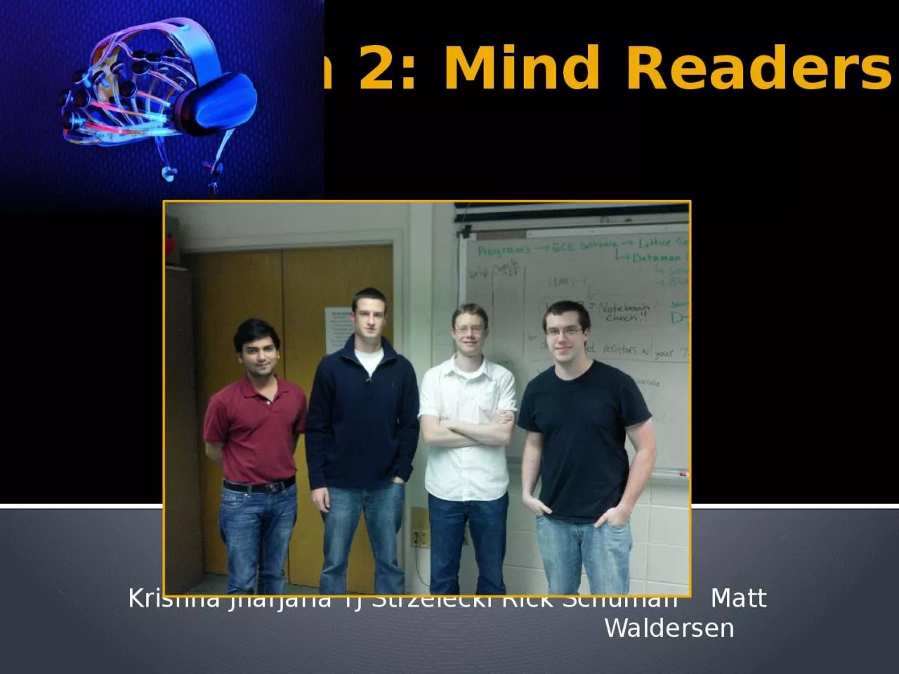
Jharjaria TJ Strzelecki Rick Schuman Matt Waldersen Project Overview The Mind Reader is a mobile braincomputer interface Computer applications will be presented to the user through commercially available video glasses ID: 1046837

reference eog main pcb eog reference pcb main layout eeg pass software order ann module amp signal design user

Share:

Link:

Embed:

Download Presentation from below link

Download Presentation The PPT/PDF document "Team 2: Mind Readers Krishna" is the property of its rightful owner. Permission is granted to download and print the materials on this web site for personal, non-commercial use only, and to display it on your personal computer provided you do not modify the materials and that you retain all copyright notices contained in the materials. By downloading content from our website, you accept the terms of this agreement.


Presentation Transcript

1. Team 2: Mind ReadersKrishna Jharjaria TJ Strzelecki Rick Schuman Matt Waldersen

2. Project OverviewThe Mind Reader is a mobile brain-computer interface.Computer applications will be presented to the user through commercially available video glasses.An EOG and commercially available EEG will be mounted inside of a common enclosure and will enable the user to navigate and select various applications.A dsPIC microcontroller will be used to acquire the EOG and EEG signals, the EEG signals will be analyzed by an FPGA and a BeagleBoard XM will control the virtual reality environment as well as execute all of the computer applications

3. Project-Specific Success CriteriaAn ability to encode/decode data packets from a NeuroSky EEG.An ability for a user to select applications based on signals from a NeuroSky EEG.An ability for a user to navigate between different applications on a display using EOG signals.An ability for the system to interactively train the user to effectively operate the device.An ability to display a live video stream from an external camera module, and integrate applications into the video system.

4. Block Diagram

5. Component Selection RationaleMicrocontrollerConsiderationsSignal Processing abilitiesDigital Communication pinsOptimized for C compilerProcessing speedResources and reference materialDSPIC33EP512MU810Extensive DSP Library with built in FFT function4-UART; 4-SPI; 2-I2COptimized for C compiler~53K of RAMLarge online community

6. EOG Op-Amp Selection Rationale (TLC2272/4 & TLV2211 )Low NoiseDual PolarityModel Available in PSPICEMultiple Op-Amp ModelsAvailable in DIP and SMD configurationsWith exception of the TLV2211High Accuracy

7. EOG Op-Amp Selection Criteria

8. ADC Selection Rationale (ADS1210)High Resolution 19.5 Effective Resolution (Bits RMS)Differential input and 2.5V reference output eliminates need for virtual groundIntegrated Programmable Gain AmplifierIntegrated Digital FilterAvailable in both DIP and SMD packages

9. ConsiderationsSize (Logic Blocks)Number of I/O PinsBuilt in FunctionalityPower ConsumptionDLP-HS-FPGA3 USB - FPGA Module25,344 Logic Blocks (11,264 slices)63 Available user I/O channels32 Dedicated Multipliers, libraries for floating point arithmeticFPGA module contains: regulators, clock generator, SDRAM, USB programmer, SPI Flash, compatible with Xilinx ISE WebPackFPGA operates on 3.3V, sinks/sources approximately 24mA per I/O pinComponent Selection RationaleFPGA Module

10. BeagleBoard-xM1.0 GHz ARM Cortex-A8 Processor512 MB RAM8 GB microSD HDD libraries and main program4 USB 2.0 Slots Mouse/Keyboard dev, WebcamExpansion Header (Data Transfer)o SPIo UARTo I2Co GPIOComponent Selection RationaleBeagleBoard xM

11. Packaging DesignModular designMaintains separation of digital circuitry and sensitive analog EOG circuitryEnables the EOG circuitry to be placed as close possible to signal electrodesVideo glasses will be used in order to ensure that the video display is directly in front of the field of viewLight Weight Single Board Computer

12. Packaging DesignBeagleBoard-xMSize: 3.35” x 3.45”Weight: < 1 lb.Logitech C310 HD Cam1280x720p frame capture< 8 oz.Vuzix Wrap 920Twin 640x480p Display< 3 oz.

13. Main Circuit BoardEOG inputsPower SupplyMicrocontroller InterfaceFPGA and Beagle Board

14. Power Supply11.1V rechargeable Lithium ion Battery5V convertorFor FPGA and Beagle Board3.3 V convertorFor Microcontroller2 Switch Mode regulators

15. EOG inputsConnected to EOGvia SPIConnected to EOG via SPILogic Level convertorFrom 5V to 3.3VRegistered Jack (RJ11)

16. Micro, in-system-programmer, EEG Dongle, OscillatorOscillatorIn System ProgrammerPCB mountResetThrough holeReset ConnectionsSwitch debouncerPin 13 MCRLPin 15 PGECPin 16 PGEDEEG input via UART

17. UNIVERSAL ASYNCHRONOUS RECEIVER TRANSMITTER (UART)Baud rate = 115200 bpsSpecified by the NeuroSky MindWave

18. EEG signals FFTEEG frequency range 4-7hzArray size 512Output of the FFT resides in RAMInbuilt FFT API: FFTComplexIP() BitReverseComplex() SquareMagnitudeCplx()4-7hz

19. FPGA Module, Logic Level Converter, Beagle BoardBeagle BoardFPGA ModuleLogic Level ConvertorFrom 3.3V to 5VSelect buttonSwitch debouncer4 bit EOG outputUp, down, left, right2x5 bit EOG input4 I/O for EOG3 SPI pins for EEG

20. PCB LayoutDesign ConsiderationsMain BoardMultiple Voltages neededPower Traces at least 40 mil, signal traces no smaller than 10 milIsolate oscillatorPhysical location of connectors Decoupling CapacitorsEOG BoardSensitive analog circuitryDistance between electrodes and filtering/amplificationPhysical size of EOG PCB

21. PCB Layout

22. PCB Layout – Main BoardFGPA Module

23. PCB Layout – Main BoardFGPA Module

24. PCB Layout – Main BoarddsPIC Micro

25. PCB Layout – Main BoarddsPIC Micro

26. PCB Layout – Main BoardPower Supply

27. PCB Layout – Main BoardPower Supply

28. PCB Layout – Main BoardEOG/SBC Connection & LLT

29. PCB Layout – Main BoardEOG/SBC Connection & LLT

30. EOG Theory of OperationElectrooculography measures the signal given off of corneo-retinal potentials in the eyesAn EOG circuit consists of an instrumentation amplifier, amplifiers, low pass filtering and high pass filteringA high pass filter is used to eliminate a naturally occurring DC driftA low pass filter is used to remove all other external noise

31. Instrumentation AmplifierInstrumentation AmplifierHigh Input ImpedanceIncludes both a high pass filter to eliminate DC drift and a second order low pass filter

32. Instrumentation Amplifier

33. Sallen-Key 2nd Order LPFSallen-Key 2nd-Order Low Pass FilterEliminates noise from external sources

34. Sallen-Key 2nd Order LPF

35. First Order LPF - AmplifierFirst Order Low Pass Filter – Amplifier CircuitEliminates noise as well as amplifies the signal

36. First Order LPF - Amplifier

37. Linear Regulator

38. Voltage Inverter

39. Analog-to-Digital Converter

40. Reference Ground & Input Jack

41.

42. EOG Signal ConditioningVoltage (V)Time (s)

43. EOG Signal ConditioningVoltage (V)Time (s)

44. Normalizing EOG Signal∆VoltageSample Number

45. Software Design/Development StatusArtificial Neural NetworkWhat is an Artificial Neural Network?Simplified mathematical model of the human brainUtilizes a network of “neurons” to model relationships between inputs and outputsHow does a ANN work?ANN implement non-linear functions in each neuronThis function sums weighted input values and passes them through a non-linear function, usually a Sigmoid functionThis output then propagates to further network layers for the process to be repeatedWhy use an FPGA implementationHighly parallel algorithm, with transistor like outputNeed for quick, complex calculations

46. Software Design/Development StatusArtificial Neural Network

47. Software Design/Development StatusArtificial Neural NetworkBasics of A NeuronEach neuron contains a number of synapses, one for each previous layer neuron connectedA synapses will take inputs and multiply it by a predetermined specific weightThe weighted values will then be accumulated and funneled into a nonlinear activation function (Sigmoid Function)Hardware Design ConsiderationsNeed multiple multipliers, one for each synapses (38 multipliers)Need to condense the size of a neuronUsing control logic and multiple clock cycles we can lower the required multipliers to a single multiplier per neuron (12 multipliers)Implementation of non-linear Sigmoid FunctionLook-up Table

48. Artificial Neural NetworkPreliminary Block Diagram

49. Software Design/Development StatusArtificial Neural NetworkWhere we proceed from hereTraining and testing of preliminary ANN using Matlab ANN toolboxThis will allow the weighted values to be hardcoded into the FPGADesign and testing of single neuron in VHDLDevelopment of a proven working topology

50. Software Design/Development StatusHeads-Up DisplayTentative HUD Features Webcam Live FeedEEG Signal Data displayHome Screen3 x 3 application layoutConcentration to select appProgramsMinimal key inputClosed apps return to Home

51. Software DesignSingleboard Program Flow Diagram

52. Project Completion TimelineOctober 15-19PCB Proof of PartsOctober 22-26Simple Software SuiteSample EOG circuitADC microcontroller communicationOctober 29 – Nov 2Micro to Single-board communicationEOG ANN finished in MATLABNov 5 – Nov 9Live Feed Visual Software SuiteEEG ANN prototyped in MATLABPCB assembledNov 12 – 16EOG ANN finished on FPGANov 19 – 23Software Test ApplicationUser Training ApplicationNov 26 – Nov 30TroubleshootDec 3 – Dec 7Project Complete

53. Questions?

54. Reference (DSPIC33EP)

55. Reference (PIC Programmer)

56. Reference (RJ-12 Connection)

57. Reference (Oscillator/Reset)

58. Reference (DC Voltage Inv)

59. Reference (ADS1210 ATD)

60. Reference (TLC2272)

61. Reference (TLC2272)

62. Reference (TLV2211)

63. Reference(DLP FPGA Module)

64. Reference (MAX764-DC Inverter)