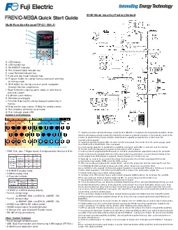
/
recommended capacity2 Install a magnetic contactor MC for each inverte recommended capacity2 Install a magnetic contactor MC for each inverte

recommended capacity2 Install a magnetic contactor MC for each inverte - PDF document

lam
lam . @lam
Follow
347 views
Uploaded On 2021-08-18

recommended capacity2 Install a magnetic contactor MC for each inverte - PPT Presentation

149FWD Rev plus 7 Digital inputs Configurable for Source or Sink1492 010VDC analog inputs149420mA analog input1494 Transistor outputs1492 010V or 420mA analog outputs149Form A contact relayo250VAC ID: 866424

motor control alarm output control motor output alarm 149 speed voltage input torque run terminal current vector opon terminals

Share:

Link:

Embed:

Download Presentation from below link

Download Pdf The PPT/PDF document "recommended capacity2 Install a magnetic..." is the property of its rightful owner. Permission is granted to download and print the materials on this web site for personal, non-commercial use only, and to display it on your personal computer provided you do not modify the materials and that you retain all copyright notices contained in the materials. By downloading content from our website, you accept the terms of this agreement.


Presentation Transcript

1 recommended capacity.*2 Install a magnet
recommended capacity.*2 Install a magnetic contactor (MC) for each inverter to separate the inverter from the power supply, apart from the MCCB or RCD/ELCB, when necessary.Connect a surge absorber in parallel when installing a coil such as the MC or solenoid near the inverter.*3 The R0 and T0 terminals are provided for inverters of 2 HP or above.To retain an alarm output signal ALM issued on inverter's programmable output terminals by the protective power-factor, regenerative PWM converter (RHC series).Use a DCR when the capacity of the power supply transformer exceeds 500 kVA and is 10 times or more the inverter rated capacity, or when there are thyristor-driven loads in the same power supply line.*6 Inverters of 15 HP or below have a built-in braking resistor (DBR) between the terminals P(+) and DB.*7 A grounding terminal for a motor. Use this terminal if needed.the shield of them to the common terminals of the control circuit. To prevent malfunction due to noise, keep *9 The connection diagram shows factory default functions assigned to digital input terminals [X1] to [X7], The connection diagram shows factory default functions assigned to digital input terminals [X1] to [X7], [30A/B/C].*10 Switching connectors in the main circuits. For details, refer to " Switching connectors" later in this section.*11 Slide switches on the control printed circuit board (control PCB). Use these switches to customize the 1 Slide switches on the control printed circuit board (control PCB). Use these switches to customize the For opening and closing the hardware circuit between terminals [EN] and [PLC], use safety components such as safety relays and safety switches that comply with EN954-1, Category 3 or higher. Be sure to use shielded •FWD, Rev, plus 7 Digital inputs. Configurable for Source or Sink.•2 0-10VDC analog inputs.•4-20mA analog input.•4 Transistor outputs.•2 0-10V or 4-20mA analog outputs.•Form A contact relayo(250VAC 0.3A, cosØ=0.3), (48VDC, .5A).•Form C contact relayo(250VAC 0.3A, cosØ=0.3), (48VDC, .5A).•24VDC max 200mA DC output power.•10VDC output power for potentiometer.•2 Source only, safe torque off Enable Inputs.•RS-485 wiring connections.Other Control Terminal •RJ-45 keypad connection port.•USB Type B connection port when using USB keypad (TP-E1U).•3 Option card expansion ports.A. LED display. B. LED monitor bar.C. RUN/STOP indicator. D. Run direction/stop indicator bar.E. Local Remote indicator bar.F. Hand and Jog mode indicator bars. Multi-Function Keypad TP-G1 (W)-J1 FRENIC-MEGA ABCDEFGHIJKMLNO Min.Max. Operang Voltage (Sink)O level 22V27V Operang Voltage (Sink)O level 0V2V Item ON level0V2VON level22V27V Max. OperangON level2V VoltageO level 27V 50m A Item Maximum Current at on. Yellow = Analog InputsControl Card Terminals SINK Mode Input by Factory Default Quick Start Menus Fuji Electric Corp. of America47520 Westinghouse Drive, Fremont, CA 94539www.americas.fujielectric.com 0. Quick set1. Data Set2. Data Check3. Operaon monitor4. I/0 Check5.Maintenance6. Alarm Info7. Alarm Cause8. Data Copy9. Load Factor10. User set11. Comm Debug 1.Data Set 2. Data CheckF. Fundamental CodesE. Extension CodesC. Control FunconsP. Motor ParametersH. High Performance FunconsJ. Applicaon FunconsA. Motor 2 Parametersb. Motor 3 Parametersr. Motor 4 Parametersd. Applicaon Funcons 2y. Link FunconsU. Customizable Logic Funcons 1.Input signalFWD,Rev, X1-X7 EN1, EN23.Output signalsY1-Y4, Y5AC, 30 ABCDi LinkDo LinkLNK12= Voltage on terminal 12C1= Current on terminal C1V2= Voltage on terminal V2FM1 (Volts)FM1 (AMPS)FM2 (Volts)FM2 (AMPS)Input signal Di-oOutput signalsdo-oPulse train inputX7P1= p/s of A/B phaseZ1= p/s of Z phaseP1= p/s of A/B phaseZ2= p/s of Z phase32= Voltage on terminal 32C2= Input current on terminal C2A0 Output voltage

2 on terminal A0A0 Output voltage on termi
on terminal A0A0 Output voltage on terminal CS 4. I/0 Check Analog Output signals6.Input signal via communicaon signalFWD,Rev, X1-X7,XF,XR, RST4.I/0 Signals (hexadecimal) 5.Analog Input signals2.7.8.PG Pulse rateI/0 Signal of input (opon card)9. TimeCumulave run meEDCDC link bus voltageTMPIMax temperature inside the inverter every hourTMPFMax temperature of the heat sink every hourImaxMaximum current in RMS every hourCAPCapacitance of the DC link bus capacitorMTIMCumulave motor run meREMT1Remaining me before next maintenance for motor 1TCAPCumulave run me of electrolyc capacitorsTFANCumulave run me of the cooling fanNSTNumber of startupsWhInput wa-hoursPDInput wa-hour dataREMN1Remaining startup mes before next maintenanceNRR1Number of RS-485 errorsNRR2Error code of RS-485NROCount of opon errorsMAINRom version of InverterKPRom version of KeypadOP1Rom version of opon 1OP2Rom version of opon 2OP3Rom version of opon 3TMPIMTemperature inside the inverter real me valueTMPFMTemperature of the heat sink real me valueCAPEHLifeme of DC link cpacitorCAPRHLifeme of DC link capacitorMTIM1Cumulave run me of motor 1MTIM2Cumulave run me of motor 2MTIM3Cumulave run me of motor 3MTIM4Cumulave run me of motor 4NST1Number of startups motor 1NST2Number of startups motor 2NST3Number of startups motor 3NST4Number of startups motor 4LALM1Light alarm latestLALM2Light alarm lastLALM2Light alarm 2nd lastLALM3Light alarm 3rd lastLALM4Light alarm 4th lastNROANumber of errors Opon 1NROBNumber of errors Opon 2NROCNumber of errors Opon 39.10.11.12.5. Maintenance1.2.3.4.5.6.7.8. 0/1Latest Alarm-1Last Alarm-22nd Last Alarm-33rd Last Alarm6. Alarm Info Fot1IoutVoutTRQFrefFWDRev(Blank)ILLUVLTLTIMESLM1-M4VFDTVVF-SCVF-PGVC-PGVC-PGNSTEDCTMPITMPFTRMLNKSUBSPEED Error sub-code Detected Speed 6. Alarm Info Number of startsDC link bus VoltageTemperature inside the inverterTemperature inside the heat sinkInput signals of Control circuit Input signals of Communicaon link Output Signals Mulple Alarm Mulple Alarm Dynamic torque vector control speed sensor Vector control without speed sensor ForwardReverse StopRun Direcon Drive ControlCurrent liming Under voltage Voltage liming V/F control without slip compensaon Dynamic torque vector control V/F control with slip compensaon Vector control with speed sensor Torque liming Cumulave run me Speed limit Motor being selected Output Frequency Output Current Output Voltage Calculated Torque Reference Frequency KP - INV ReadStore inverter program in the keypadKP-䌀 INV writeWrite program from keypad into inverterKP 䌀 INV verifyVerify the program matches saved leKPDATA Check8. Data Copy 9.Load factorHours SETStart-�Stop 10. User setSelect the funcon codes for quick start menu Fot1Fot2 Iout Vout TRQ FrefFWDForwardRevReverse(Blank)Stop IL LU VL SLM1-M4VFDTV VF-SC VF-PG VC-PG VC-PGSYNLODLIN LSC SV PV MVTLATLBtrqb P E4 dP MODENTCRaFLUX SY-d P4 E4 dP4MODE Current posion pulse Stop posion target pulse Posion deviaon pulse ReservedRun Direcon Posion deviaon pulse Posioning control status Motor temperatureMagnec ux command value Deviaon in synchronous operaon Torque Limit Value A Torque Limit Value B Reference Torque Bias Stop posion target pulse Current Posion Pulse Rao seng 3. Operaon Monitor7.8. PID Output Value 2.3.4.5.6. Vector control without speed sensor Vector control with speed sensor PID Setpoint PID Feedback Value Motor Speed Load Sha Speed Line Speed Constant peripheral speed control monitor 1. V/F control without slip compensaon Dynamic torque vector control V/F control with slip compensaon Dynamic torque vector control speed sensor Frequency Specied by a Frequency command Current Liming Under voltage detected Voltage Liming Speed Liming Motor 1-4 Output Frequency Before slip compensaon Output Frequency aer slip compensaon Out put Current Output Voltage Calculated Output Torque