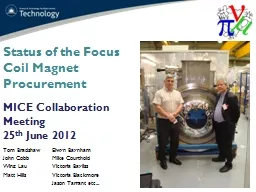
Tom Bradshaw John Cobb Wing Lau Matt Hills MICE Collaboration Meeting 25 th June 2012 Elwyn Baynham Mike Courthold Victoria Bayliss Victoria Blackmore Jason Tarrant etc Talk will cover Recent progress at TESLA Configuration and Schedule ID: 445290
Download Presentation The PPT/PDF document "Status of the Focus Coil Magnet Procurem..." is the property of its rightful owner. Permission is granted to download and print the materials on this web site for personal, non-commercial use only, and to display it on your personal computer provided you do not modify the materials and that you retain all copyright notices contained in the materials. By downloading content from our website, you accept the terms of this agreement.
Slide1
Status of the Focus Coil Magnet Procurement
Tom BradshawJohn CobbWing LauMatt Hills
MICE Collaboration Meeting
25th June 2012
Elwyn BaynhamMike CourtholdVictoria BaylissVictoria BlackmoreJason Tarrant etc...Slide2
Talk will cover: Recent progress at TESLA, Configuration and Schedule
IntroductionSlide3
Recent Progress and Status
Radiation shields fittedCold mass installed Cold mass sensor wiring completeSupports tensionedAlignment of cold mass completedSlide4
Alignment of Cold Mass
Picture shows the space for the installation of the force transducers for accurate tensioning of the straps.We will monitor these during cool-down – the straps will contract by ~1.26mm
Dummy force transducer shown in position
Jig for installing force transducerSlide5
Pre-stress of suspension
Strap 1 0.51Mid link 0.05Strap 2 0.64OVC link 0.06Reduction in force due to OVC and foot deformation of 0.17mm
Getting ~200kN from stress on
cooldown which means that only a minimum room temperature pre-stress is required. This will be monitored during cool-down.Slide6
Alignment of Cold Mass
Wing and Jason witnessed the alignment and strap tensioning on the 18th.Cold mass accurately centred Worryingly, the position of the flange hole centres is +/- 0.7mm on best fit pitch circle diameter which is out of tolerance. Best guess is that stress relieving of the OVC over time has caused this – we are investigating.
Survey report is available.We are looking into either over- drilling on the existing bellow flange holes to match the surveyed hole positions on the OVC, or create a new set of holes at half pitch to the existing holes. In other words, the bellow flange
will simply have holes to mate the two adjacent modules whatever their hole positions are.The Helium side is aligned to within 128 microns and -87 microns in the x and y coordinates respectively and the Hydrogen side is aligned to -113 and 67 microns. The required tolerance is ±250 microns. Slide7
Recent Progress and Status
Wiring showing the tails exiting the cold massSlide8
Odds and Ends
Poorly performing Cryomech cooler has been returned from US – second one now has to be shipped back.Control and instrumentation is all now available and will be shipped to RAL soon.Power supplies have arrived and will also be shipped to RAL soon.
Operating points
Flip mode
Solenoid mode200 MeV/c240 MeV/c200 MeV/c
240 MeV/c
Current
187.14
224.75
94.15
113.09
Current density
NbTi
584.82
702.35
294.23
353.41
Current density coil
104.75
125.80
52.70
63.30
Bz max
3.090
3.711
2.598
3.121
Bpeak conductor
6.264
7.523
3.763
4.520Slide9
HTS Lead thermal link
Some off-line measurements are being made on the thermal link between the HTS leads and the cryocooler mid stage. This is a critical joint.Found that Cu/Stycast/0.2mm FR4/Stycast/Cu joint is not as good as sandwich with 50µm
KaptonKapton is ~ x2 better than the FR4 and can withstand 4kVSlide10
R9 Facility
Chiller for cryocoolers
Area cleared and
Yellow line for 5 Gauss limit..
ScaffoldingCERN Field Measurement equipment Slide11
Schedule
Module/ActivityDue DateAFC1 at RAL
JulyAbsorber integration and test
+3mths elapsedAFC2 at RALSeptemberAbsorber integration and test<3mthsSlide12
END