/
MIPS Processor MIPS Processor

MIPS Processor - PDF document

lucinda
lucinda . @lucinda
Follow
346 views
Uploaded On 2020-11-23

MIPS Processor - PPT Presentation

1 
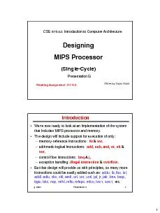
Designing Single Cycle Presentation G CSE 67502 Introduction to Computer Architecture Slides by Gojko Babi ć Reading Assignment 51 54 g babic Presentation G 2 Were now ready to ID: 821302

control clock presentation babic clock control babic presentation cycle alu instructions instruction unit write datapath add design nsec type

Share:

Link:

Embed:

Download Presentation from below link

Download Pdf The PPT/PDF document "MIPS Processor" is the property of its rightful owner. Permission is granted to download and print the materials on this web site for personal, non-commercial use only, and to display it on your personal computer provided you do not modify the materials and that you retain all copyright notices contained in the materials. By downloading content from our website, you accept the terms of this agreement.


Presentation Transcript

1Designing MIPS Processor(Single-Cy
1Designing MIPS Processor(Single-Cycle)Presentation GCSE 675.02: Introduction to Computer ArchitectureSlides by GojkoBabićReading Assignment:5.1-5.4g. babicPresentation G2•We're now ready to look at an implementation of the system that includes MIPS processor and memory.•The design will include support for execution of only:–memory-reference instructions: lw &sw,–arithmetic-logical instructions: add,sub,and,or,slt &nor,–control flow instructions: beq &j,–exception handling:illegal instruction &overflow.•But that design will provide us with principles, so many more instructions could be easily added such as: addu,lb, lbu, lui, addi, adiu, sltu, slti, andi, ori, xor, xori, jal, jr, jalr, bne, beqz, bgtz, bltz, nop, mfhi, mflo, mfepc, mfco, lwc1, swc1, etc.Introduction2g. babicPresentation G3•Wewill first design a simpler processor that executes each instruction in only one clock cycle time.•This is not efficient from performance point of view, since:–a clock cycle time (i.e. clock rate) must be chosen such that the longest instruction can be executed in one clock cycle and–that makes shorter instructions execute in one unnecessarily long cycle.•Additionally,

no resource in the design may be used mo
no resource in the design may be used more than once per instruction, thus some resources will be duplicated.•The singe cycle design will require:–two memories (instruction and data),–two additional adders. Single Cycle Designg. babicPresentation G4Elements for Datapath Design1632Signextendg.Sign-extensionunit3232h. Shift left 2ShiftLeft 2PCa.Programcounter3232RegWriteRegistersWriteregisterReaddata1Readdata2Readregister1Readregister2WritedataDataDataRegisternumbersb.RegisterFile555323232AddSumd.Adder323232MemReadMemWriteDatamemoryWritedataReaddatae.DatamemoryunitAddress323232InstructionmemoryInstructionaddressInstructionf.Instructionmemory3232MemRead=1MemWrite =0c.ALUALUcontrolALUres ultALUZero4323232overflow3g. babicPresentation G5•This generic implementation:–uses the program counter (PC) to supply instruction address,–gets the instruction from memory,–reads registers

,–uses the instruction opcodeto d
,–uses the instruction opcodeto decide exactly what to do.RegistersRegister#DataRegister#DatamemoryAddressDataRegister#PCInstructionALUInstructionmemoryAddressAbstract /Simplified View (1stlook)g. babicPresentation G6Abstract /Simplified View (2ndlook)Figure 5.1•PC is incrementedby 4 by most instructions, and 4 + 4×offsetby branch instructions.•Jump instructions change PC differently (not shown).4g. babicPresentation G7•An edge triggered methodology•Typical execution:–read contents of some state elements at the beginning of the clock cycle, –send values through some combinational logic,–write results to one or more state elements at the endof the clock cycle. Our ImplementationClockcycleStateelement1CombinationallogicStateelement2•An edge triggered methodology allows a state element to be read and written in the same clock cycle. Figure 5.5g. babicPresentation G8PCInstructionmemoryReadaddressInstruction4AddIncrementing PC & Fetching InstructionClockFigure 5.6with addition in red5g. babicPresentation G9

Datapath for R-type InstructionsR-
Datapath for R-type InstructionsR-type 000000 rs rt rd 00000 funct 31 26 25 21 20 16 15 11 10 6 5 0add = 32sub = 34slt = 42and = 36 or = 37nor = 39InstructionRegistersWriteregisterReaddata1Readdata2Readregister1Readregister2WritedataALUresultALUZeroRegWrite4I25-21I20-16I15-11ClockALU controlg. babicPresentation G10Complete Datapath for R-type InstructionsPCInstructionmemoryReadaddressInstruction4AddclockBased on contents of op-code and funct fields, Control Unit sets ALU control appropriately and asserts RegWrite, i.e. RegWrite = 1. RegistersWriteregisterReaddata1Readdata2Readregister1Readregister2WritedataALUresultALUZeroRegWrite4I25-21I20-16I15-11ClockALU control6g. babicPresentation G11Datapath for LW and SW InstructionsControl Unit sets: •ALU control = 0010 (add) for address calculation for both lw and sw•MemRead=0, MemWrite=1

and RegWrite=0for sw•MemRead=1, M
and RegWrite=0for sw•MemRead=1, MemWrite=0 and RegWrite=1for lw31 26 25 21 20 16 15 0sworlwopcode rs rt offsetInstruction1632RegistersWriteregisterReaddata1Readdata2Readregister1Readregister2DatamemoryWritedataReaddataWritedataSignextendALUresultZeroALUAddressMemReadMemWriteRegWriteALU4I25-21I20-16I20-16I15-0controlMemWriteClockg. babicPresentation G12Datapath for R-type, LW & SW InstructionsLet us determine setting of control lines for R-type, lw & sw instructions.PCInstructionmemoryReadaddressInstruction1632RegistersWriteregisterWritedataReaddata1Readdata2Readregister1Readregister2SignextendALUresultZeroDatamemoryAddressWritedataReaddata4AddALUALU control4MemReadMemWriteALUSrcMemtoReg010110RegDstClock

rsrtrdMemRead =1MemWrite =0Clocko
rsrtrdMemRead =1MemWrite =0ClockoffsetWriteClockReg7g. babicPresentation G1331 26 25 21 20 16 15 0beq rsrtoffsetDatapath for BEQ InstructionBranch target = [PC] + 4 + 4×offset1632SignextendZeroALUSumShiftleft2TobranchcontrollogicBranchtargetPC+4frominstructiondatapathInstructionAddRegistersWriteregisterReaddata1Readdata2Readregister1Readregister2WritedataRegWriteALU control4rsrtFigure 5.9with additions in redoffsetg. babicPresentation G14Datapath for R-type, LW, SW & BEQFigure 5.15with additions in redMemtoRegMemReadALUSrcRegDstPCInstructionmemoryReadaddressInstruction[31–0]Instruction[20–16]Instruction[25–21]Add41632Instruction[15–0]0RegistersWriteregisterWritedataWritedataReaddata1Readdata2Readregister1Readregister2Si

gnextendALUresultZer
gnextendALUresultZeroDatamemoryAddressReaddataMux11Mux01Mux01Mux0Instruction[15–11]Shiftleft2PCSrcALUAddALUresultALU controlclock4MemRead=1MemWrite=0rsrtrdoffsetMemWriteClockWriteClockReg8g. babicPresentation G15PCInstructionmemoryReadaddressInstruction[31–0]Instruction[2016]Instruction[2521]AddInstruction[50]MemtoRegALUOpMemWriteRegWriteMemReadBranchRegDstALUSrcInstruction[3126]41632Instruction[150]00Mux01ControlAddALUresultMux01RegistersWriteregisterWritedataReaddata1Readdata2Readregister1Readregister2SignextendMux1ALUresultZeroPCSrcDatamemoryWritedataReaddataMux1Instruction[1511]ALUcontrolShiftleft2ALUAddressControl Unit and DatapathClockMemRead=1MemWrite=0Clock andedClock andedFigure 5.17with additions in redrsrtrd

functoffsetopcodeg. babicPresentatio
functoffsetopcodeg. babicPresentation G16Op-codeRegDstALUSrcMemto-RegReg WriteMem ReadMem WriteBranchALUOp1ALUp00000001001d0010100011011110000101011d1d001000000100d0d0d0101Truth Table for (Main) Control UnitInputOutputR-typelwswbeq•ALUOp[1-0] = 00signal to ALU Control unit for ALU to perform add function, i.e. set Ainvert = 0, Binvert=0and Operation=10•ALUOp[1-0] = 01signal to ALU Control unit for ALU to perform subtract function, i.e. set Ainvert = 0, Binvert=1and Operation=10•ALUOp[1-0] = 10signal to ALU Control unit to look at bits I[5-0]and based on its pattern to set Ainvert, Binvert and Operation so that ALU performs appropriate function, i.e. add, sub, slt, and, or & nor9g. babic17Truth Table of ALU Control UnitALUOpFunct fieldALU ControlALUOp1ALUOp0F5F4F3F2F1F000dddddd0 0 1001dddddd0 1 10101000000 0 10101000100 1 10101001000 0 00101001010 0 01101010100 1 11addsubaddsubandorsltnorInput Output101001111 1 00Ainvert BivertOperationg. babic18R-formatIwswbeqOp0Op1Op

2Op3Op4Op5InputsOutp
2Op3Op4Op5InputsOutputsRegDstALUSrcMemtoRegRegWriteMemReadMemWriteBranchALUOp1ALUOpOOp-codebits5 4 3 2 1 0RegDstALUSrcMemto-RegReg WriteMem ReadMem WriteBranchALUOp1ALUp00 0 0 0 0 01001d00101 0 0 0 1 10111100001 0 1 0 1 1d1d0010000 0 0 1 0 0d0d0d0101Design of (Main) Control UnitRegDst =Op5Op4Op3Op2Op1Op0ALUSrc= Op5Op4Op3Op2Op1Op0+Op5Op4Op3Op2Op1Op000…0…0Figure C.2.510g. babic19PC+4[31–28]Datapath for R-type, LW, SW, BEQ & JPC PC31-28|| jump_target || 0031 26 25 0jjump_targetPC[31-28]Add2zerosFigure 5.24with correction in redPCInstructionmemoryReadaddressInstruction[31–0]DatamemoryReaddataWritedataRegistersWriteregisterWritedataReaddata1Readdata2Readregister1Readregister2Instruction[15–11]Instruction[20–16]Instruction[25–21]AddA

LUresultZeroInstruct
LUresultZeroInstruction[5–0]MemtoRegALUOpMemWriteRegWriteMemReadBranchJumpRegDstALUSrcInstruction[31–26]4MuxInstruction[25–0]Jumpaddress[31–0]Signextend1632Instruction[15–0]1Mux10Mux01Mux01ALUcontrolControlAddALUresultMux010ALUShiftleft22628Addressshiftleft 2g. babic20Design of Control Unit (J included)…0J 0 0 0 0 1 0 d d d 0 d 0 d d d Op-codebits5 4 3 2 1 0RegDstALUSrcMemto-RegReg WriteMem ReadMem WriteBranchALUOp1ALUp00 0 0 0 0 01001d00101 0 0 0 1 10111100001 0 1 0 1 1d1d0010000 0 0 1 0 0d0d0d0101Jump00001R-formatIwswbeqOp0Op1Op2Op3Op4Op5InputsRegDstALUSrcMemtoRegRegWriteMemReadMemWriteBranchALUOp1ALUOpOJumpJump =Op5Op4Op3Op2Op1Op0No changes in ALU Control unit11g. babicPresentation G21•Let us assume that the onlydelays introduced ar

e by the following tasks:–Memory ac
e by the following tasks:–Memory access (read and write time = 3 nsec)–Register file access (read and write time = 1 nsec)–ALU to perform function (= 2 nsec)•Under those assumption here are instruction execution times:Instr Reg ALU Data Regfetch read oper memory write TotalR-type 3 + 1 + 2 + 1 = 7 nseclw 3 + 1 + 2 + 3 + 1 = 10 nsecsw 3 + 1 + 2 + 3 = 9 nsecbranch 3 + 1 + 2 = 6 nsecjump 3 = 3 nsec•Thus a clock cycle time has to be 10nsec, and clock rate = 1/10 nsec = 100MHzCycle Time Calculation g. babicPresentation G22•Single Cycle Problems:–what if we had a more complicated instruction like floating point?–a clock cycle would be much longer, –thus for shorter and more often used instructions, such as add & lw, wasteful of time.•One Solution:–use a “smaller” cycle time, and–have different instructions take different numbers of cycles.•And that is a “multi-cycle” processor.Single Cycle Processor: Conclus