PDF-AUTOMATIC UPPER DIPPER FOR VEHICLE
W
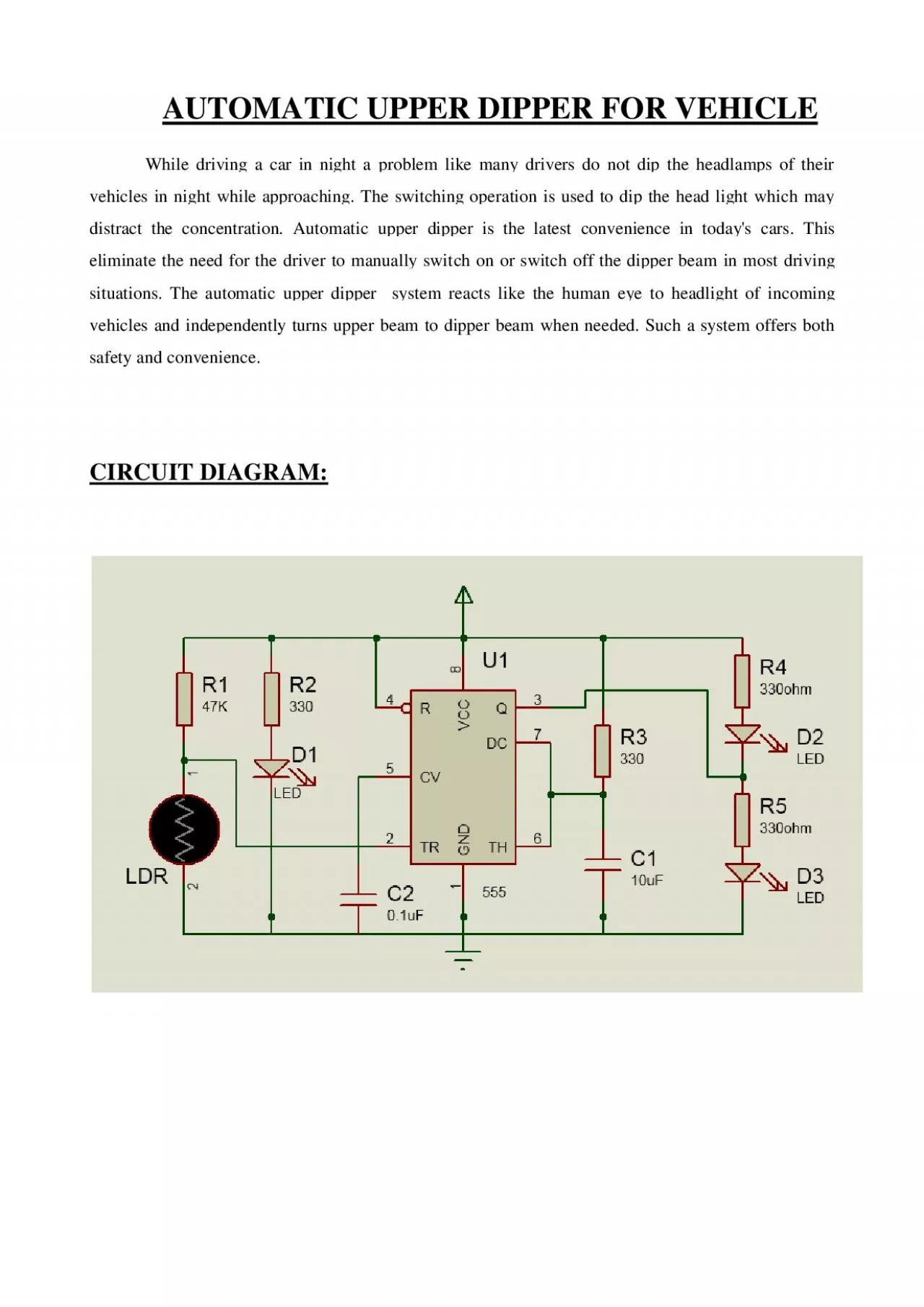
hile driving a car in night a problem like many drivers do not dip the headlamps of their vehicles in night
while approaching The switching operation is used to
Download Presentation
"AUTOMATIC UPPER DIPPER FOR VEHICLE" is the property of its rightful owner. Permission is granted to download and print materials on this website for personal, non-commercial use only, provided you retain all copyright notices. By downloading content from our website, you accept the terms of this agreement.
Presentation Transcript
Transcript not available.