/
Monday Case of the Day History: Monday Case of the Day History:

Monday Case of the Day History: - PowerPoint Presentation

mia
mia . @mia
Follow
0 views
Uploaded On 2024-03-13

Monday Case of the Day History: - PPT Presentation

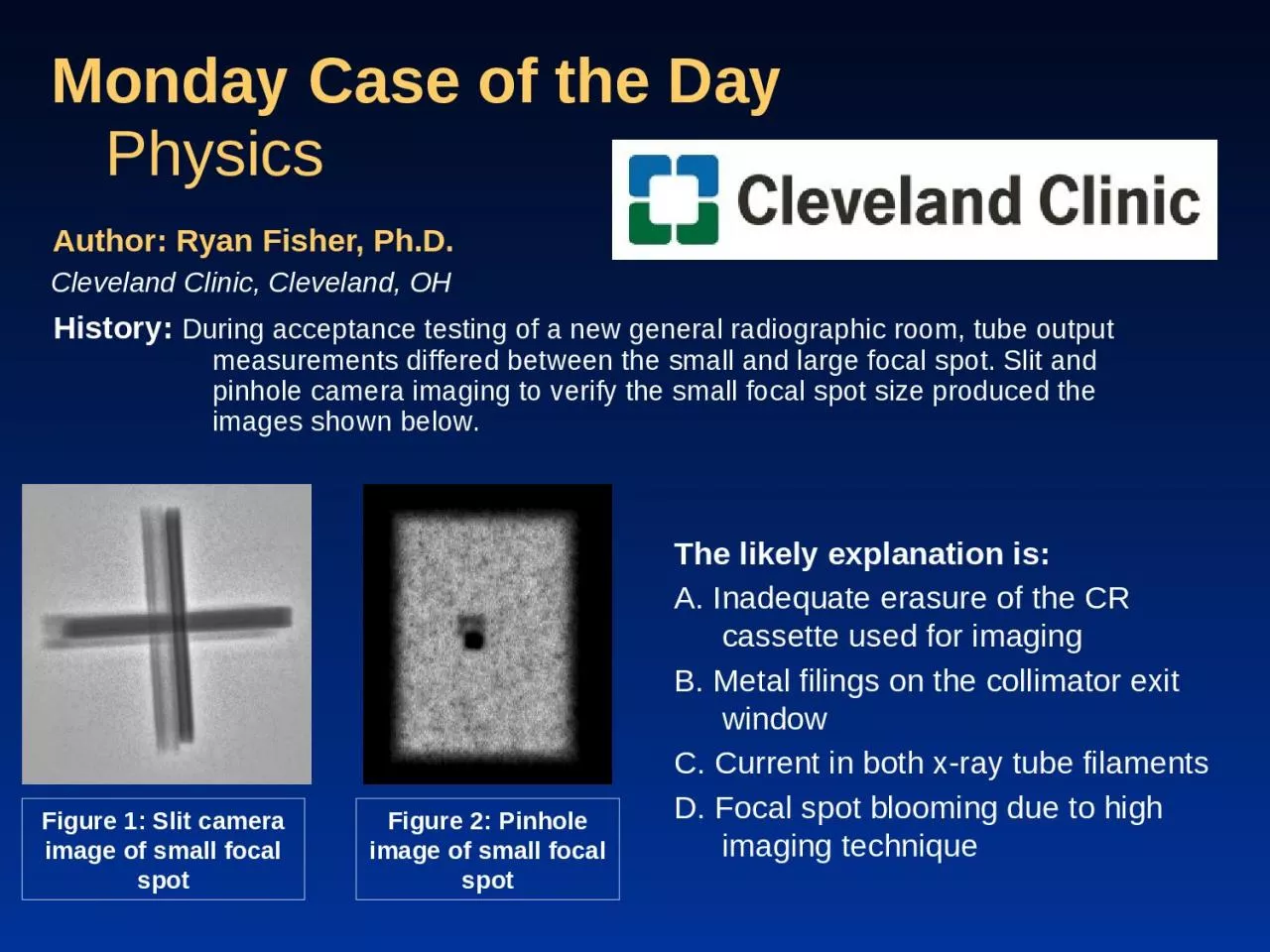
During acceptance testing of a new general radiographic room tube output measurements differed between the small and large focal spot Slit and pinhole camera imaging to verify the small focal spot size produced the images shown below ID: 1048192

spot focal large small focal spot small large pinhole images camera tube current image slit size output ray ghosted

Share:

Link:

Embed:

Download Presentation from below link

Download Presentation The PPT/PDF document "Monday Case of the Day History:" is the property of its rightful owner. Permission is granted to download and print the materials on this web site for personal, non-commercial use only, and to display it on your personal computer provided you do not modify the materials and that you retain all copyright notices contained in the materials. By downloading content from our website, you accept the terms of this agreement.


Presentation Transcript

1. Monday Case of the DayHistory: During acceptance testing of a new general radiographic room, tube output measurements differed between the small and large focal spot. Slit and pinhole camera imaging to verify the small focal spot size produced the images shown below.Author: Ryan Fisher, Ph.D.Cleveland Clinic, Cleveland, OHPhysicsFigure 2: Pinhole image of small focal spotThe likely explanation is:A. Inadequate erasure of the CR cassette used for imagingB. Metal filings on the collimator exit windowC. Current in both x-ray tube filamentsD. Focal spot blooming due to high imaging techniqueFigure 1: Slit camera image of small focal spot

2. Findings: The tube output per mAs for the small focal spot was found to be approximately 30% higher than for the large focal spot.Slit camera images of the large focal spot appeared normal and focal spot size measurements were within tolerances. Slit camera and follow up pinhole camera images of the small focal spot showed a lower intensity ghosted shadow artifact, seen in Figures 1 & 2. Measurements of the darker areas of each were within tolerances for the small focal spot size.Measurements showed the ghosted shadow size corresponded to the measured size of the large focal spotFigure 2: Pinhole image of small focal spotFigure 1: Slit camera image of small focal spotSmall focal spotGhosted shadow artifact

3. Findings: Figure 3: SFS pinhole image with current to large focal spot shut offThe service engineer was consulted and the small focal spot pinhole images were repeated with the filament current to the large focal spot completely shut off, producing the image seen in Figure 3 below.The tube output per mAs for the small focal spot was re-measured with the current to the large focal spot filament cut off, and results were in line with what was previously measured with the large focal spot.Figure 4: Original SFS pinhole image

4. Diagnosis: C. Current in both x-ray tube filaments

5. While inadequate erasure of a CR cassette can lead to image artifacts, it is not likely that they would correspond so well with the actual focal spot images. This choice would also not explain the tube output discrepancy between the large and small focal spots. Therefore, choice A, “inadequate erasure of the CR cassette used for imaging,” is incorrect. Focal spot blooming can lead to inaccurate focal spot size measurements to the extent that NEMA recommends testing focal spot size for general radiographic equipment at 50% of the maximum tube current rating allowed during a 0.1 sec exposure (NEMA). All images in this case were acquired with such a technique and focal spot blooming would not explain the ghosted artifacts in both the pinhole and slit camera images. Choice D, “Focal spot blooming due to high imaging technique” is also incorrect.While debris on either the x-ray tube or collimator exit window have been shown to cause inverse pinhole effect artifacts (Cowart), such a scenario would not create the ghosted line artifacts seen in the slit camera images. Thus, choice B, “metal filings on the collimator exit window,” is also incorrect. Discussion: With the small focal spot selected, the generator was still supplying enough current to the large focal spot filament to cause electron emission and subsequent x-ray production. This additional x-ray production caused the higher tube output per mAs measured with the small focal spot, as well as the ghosted shadows visible in the slit and pinhole camera images. After all current was physically cut off from the large focal spot, the output and focal spot images for the small focal spot returned to normal. Replacement of faulty generator components corrected the issue.

6. References/Bibliography: Cowart, RW. An investigation of the inverse pinhole camera. Thesis. University of Texas Health Science Center at Houston. Graduate School of Biomedical Sciences. Houston, TX. June 1976. 111 pages.National Electrical Manufacturers Association. (1992). Measurement of dimensions and properties of focal spots of diagnostic x-ray tubes (NEMA XR 5-1992). Washington, D.C.: National Electrical Manufacturers Association.