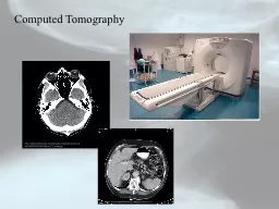
httpwwwstabroeknewscomimages20090820090830ctscanjpg httpuploadwikimediaorgwikipediacommonsarchivedda20060904231838HeadCTscanjpg http wwwcapitalhealthorgsubpagecfmref ID: 244537
Download Presentation The PPT/PDF document "Computed Tomography" is the property of its rightful owner. Permission is granted to download and print the materials on this web site for personal, non-commercial use only, and to display it on your personal computer provided you do not modify the materials and that you retain all copyright notices contained in the materials. By downloading content from our website, you accept the terms of this agreement.
Slide1
Computed Tomography
http://www.stabroeknews.com/images/2009/08/20090830ctscan.jpg
http://upload.wikimedia.org/wikipedia/commons/archive/d/da/20060904231838!Head_CT_scan.jpg
http://
www.capitalhealth.org/subpage.cfm?ref
=36Slide2
Computed Tomography
- Introduction
Computed Tomography, CT for short (also referred to as CAT, for Computed Axial Tomography), utilizes X-ray technology and sophisticated computers to create images of cross-sectional “slices” through the body.
CT exams and CAT scanning provide a quick overview of pathologies and enable rapid analysis and treatment plans.
Tomography is a term that refers to the ability to view an anatomic section or slice through the body.
Anatomic cross sections are most commonly referred to as transverse axial tomography.
The CT scanner was developed by Godfrey Hounsfield in the late 1960s.
This x-ray based system created projection information of x-ray beams passed through the object from many points across the object and from many angles (projections).
CT produces cross-sectional images and also has the ability to differentiate tissue densities, which creates an improvement in contrast resolution.Slide3
The x-ray tube in a CT
scanner is designed to produce a fan shaped beam of x-rays that is approximately as wide as your body.
The
x-ray tube on a CT
scanner is more heavy duty than tubes used for standard film imaging since the unit rotates and they operate at slightly higher energies.
Opposite the patient is an array of detectors that measure the intensity of the x-ray beam at points laterally across the patients body.
Modern CT scanners use solid state detectors that have very high efficiencies.
Solid state detectors are made of a variety of materials that create a semiconductor
junction similar to a transistor.
Ultrafast ceramic detectors use rare earth elements such as silicon, germanium,
cadmium, yttrium or gadolinium, which create a semiconducting
p-n
junction. Ceramic solid-detectors are very fast, can be extremely stable, and are produced to form an array of very small, efficient detectors that can cover a large area.
Computed Tomography
- IntroductionSlide4
Computed Tomography
- The basics
http://
www.endocrinesurgery.ucla.edu/images/adm_tst_ct_scan.jpg
http://www.themesotheliomalibrary.com/ct-scan.html
The x-rays are produced in a part of the ring and the ring is able to rotate around the patient.
The target ring contains an array of detectors and is internally cooled so the to reduce electronic noise and to cool the anode.
The patient is put into the system using a precise high speed couch.Slide5
http://www.themesotheliomalibrary.com/ct-scan.html
Computed Tomography
- The basics of image formation
The x-ray tube and detectors rotate around the patient and the couch moves into the machine.
This produces a helical sweep pattern around the patient.
The patient opening is about 70cm in diameter.
The data acquired by the detectors with each slice is electronically stored and are mathematically manipulated to compute a cross sectional slice of the body.
Three dimensional information can be obtained by comparing slices taken at different points along the body.
Or the computer can create a 3D image by stacking together slices.
As the detector rotates around many cross sectional images are taken and after one complete orbit the couch moves forward incrementally.
Willi
Kalender, Computed Tomography, Publicis Corporate Publishing 2005Slide6
Computed Tomography
- The basics of image formation
Here the x-ray tube and detector array makes many sweeps past the patient.
The x-ray tube and detector array is capable of rotating around the axis of the patient.
Each scan tries to determine the composition of each transverse cross section.Slide7
Computed Tomography
- The basics of image formation
As the x-ray tube and detectors swing around an intensity profile mapping is created.
This could also be written as an attenuation profile which is the incident intensity minus the transmitted intensity.
This generates a set of
N
equations that will be solved simultaneously for
m(x,y
) in the image reconstruction system.Slide8
Computed Tomography
- The basics of image formation
Homogeneous object, monochromatic radiation
Inhomogeneous object, monochromatic radiation
Inhomogeneous object, polychromatic radiation
In a CT scan we measure the intensity of radiation. The attenuation value,
m
, is easily determined if you have a homogeneous object. The incident intensity needs to be known and for inhomogeneous objects we need many scans to determine
m
(x,y).
m
(x,y) = ?Slide9
Computed Tomography
- The basics of image formation
Pixel
– picture element – a 2D square shade of gray.
Voxel
– volume element – a 3D volume of gray.
This is a result of a computer averaging of the attenuation coefficients across a small volume of material. This gives depth information.
Each
voxel
is about 1mm on a side and is as thick as 2 – 10mm depending on the depth of the scanning x-ray beam. Slide10
Computed Tomography
- The basics of image formation
The images are reconstructed by a method called
back projection
, or tracing
backwards along the x-rays forward path to reconstruct the image and calculating the absorption due to a localized region.
This a mathematically tedious process, but is handled easily with computers.
The detectors see the forward projected x-rays and measure the intensity, given that the x-ray intensity without the body present is known.
The intensity N
i
written as sum of attenuation coefficients along a given x-ray path.This generates a shade of gray and a number associated with this shade.Then the detector changes angles and the process repeats.Slide11
Computed Tomography
- The basics of image formation
The top scan we see that there are lighter and darker regions somewhere in it, but we don't know whether the light/dark regions is high, low, or in the middle. In other words, we know where the light region is horizontally but not vertically.
So by stretching it out we're kind of saying, "We don't know where the light spot is vertically, so for now give it
all
vertical values!”
Now do a vertical scan and now we've taken the light/ dark spots whose location we know vertically and "smeared" it out across all horizontal positions.
You can see where the light areas cross and it gets even more light there and we can start to form an image.
By "adding" more shadows medium light lines would eventually disappear and we’d have a more complete and higher resolution image.Slide12
Computed Tomography
- Hounsfield Units or CT numbers
CT numbers (or
Hounsfield units) represent the percent difference between the x-ray attenuation coefficient for a
voxel
and that of water multiplied by a constant.
Water has a CT number of zero and the numbers can be positive or negative depending on the absorption coefficient. This is how we assign a shade of gray, and 1000 is just a scaling factor set by the CT manufacturer.Slide13
Computed Tomography
- Image Quality
Number of Pixels
In images
a
and
b we have an 80 x 80 images matrix and you can easily see the discrete pixels.
In images
c
and
d
we have a 1024
x 1024 image matrix. Here the individual pixels are not seen and the image quality increases.Slide14
Computed Tomography
- Image Quality
Contrast Resolution
– The ability to differentiate between different tissue densities in the image
High Contrast
- Ability to see small objects and details that have high density difference compared with background.
- These have very high density differences from one another. - Ability to see a small, dense lesion in lung tissue and to see objects where bone and soft tissue are adjacent
Low Contrast
- Ability to visualize objects that have very little difference in density from one another.
- Better when there is very low noise and for visualizing soft-tissue lesions within the liver.
- Low contrast scans can differentiate gray matter from white matter in the brain.Slide15
Artifacts can degrade image quality and affect the perceptibility of detail.
Includes
Streaks – due to patient motion, metal, noise, mechanical failure.
Rings and bands – due to bad detector channels.Shading - can occur due to incomplete projections.
Computed Tomography
- Imaging artifacts
Streaks
Rings and bands
ShadingSlide16
Computed Tomography
- Advantages & Disadvantages
Advantages:
Desired image detail is obtained
Fast image rendering
Filters may sharpen or smooth reconstructed images
Raw data may be reconstructed post-acquisition with a variety of filtersDisadvantages
Multiple reconstructions may be required if significant detail is required from areas of the study that contain bone and soft tissue
Need for quality detectors and computer software
X
-ray exposure