/
th International & 26th All India Manufacturing Technology, Design and th International & 26th All India Manufacturing Technology, Design and

th International & 26th All India Manufacturing Technology, Design and - PDF document

natalia-silvester
natalia-silvester . @natalia-silvester
Follow
403 views
Uploaded On 2015-07-23

th International & 26th All India Manufacturing Technology, Design and - PPT Presentation

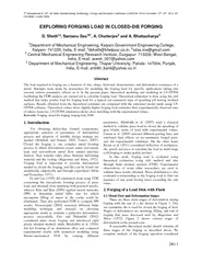
In this work forging load is evaluated using theoretical estimation using slab method and also through finite element analysis FEM Experimental observations of some other researchers are used to ID: 91309

this work forging load

Share:

Link:

Embed:

Download Presentation from below link

Download Pdf The PPT/PDF document "th International & 26th All India Manufa..." is the property of its rightful owner. Permission is granted to download and print the materials on this web site for personal, non-commercial use only, and to display it on your personal computer provided you do not modify the materials and that you retain all copyright notices contained in the materials. By downloading content from our website, you accept the terms of this agreement.


Presentation Transcript

th International & 26th All India Manufacturing Technology, Design and Research Conference (AIMTDR 2014) December 12th–14th, 2014, IIT Guwahati, Assam, India280-1 EXPLORING FORGING LOAD IN CLOSED-DIE FORGING D. Sheth1a, Santanu Das1b*, A. Chatterjee and A. BhattacharyaDepartment of Mechanical Engineering, Kalyani Government Engineering College, Kalyani- 741235, India, E-mail: dsheth@bhelpssr.co.in, sdas.me@gmail.com Central Mechanical Engineering Research Institute, Durgapur- 713209, West Bengal, India, E-mail: aveek_007@yahoo.com Department of Mechanical Engineering, Thapar University, Patiala- 147004, Punjab, India, E-mail: anb90_bank@yahoo.co.in Abstract The load required in forging are a function of size, shape, frictional characteristics and deformation resistance of a metal. Attempts were made by researchers for modeling the forging load for specific applications taking into account various parametric effects on it. In the present paper, theoretical modeling and modeling in LS-DYNA facilitating the FEM analysis are carried out to calculate forging load. Theoretical estimation is done using the slab method that helps predict load for forging lead for a typical axi-symmetric type of upsetting job having inclined surfaces. Results obtained from the theoretical estimates are compared with the simulated model made using LS-DYNA software. Theoretical values show slightly higher forging load estimates than experimentally observed ones of others; however, LS-DYNA simulation shows close matching with the experimental values. Keywords: Forging, closed die forging, forging load, FEM. 1. Introduction For obtaining defect-free formed components, appropriate selection of parameters of deformation process and adoption of suitable design strategy are needed (Abdullah and Samad, 2007, Tomov, 2007). Closed die forging is one complex metal forming process in which deformation occurs under non-steady state and non-uniform metal flow amidst interface friction. Heat transfer takes place between deforming material and the tooling (Akgerman and Altan, 1972). Forging load is important to provide deformation needed in closed die forging, and this can be found out analytically, empirically and through experiment (Altan and Fiorentino, 1971). Fu and Luo (1995) did simulation work using FEM concerning the viscoplastic forming process of press load, and obtained close matching with practical results, whereas Kim and Kim (2000) applied neural networks (NN) to determine initial billet size for which incomplete filling of metal in die cavity could be eliminated. They also performed FEM to compare NN results. Gronostajski (2000) reviewed different finite modeling technique and stressed on choosing appropriate model to simulate a particular deformation process successfully. Guo and Nakanishi (2002) considered plain strain forging and introduced rigid plastic element method, while Abedrabbo et al. (2006) did hot forming of an aluminium alloy and compared experimental results with numerical modeling using thermo-mechanical FEA by varying different parameters. Altinbalik et al. (2007) used a classical method to validate press load in closed die upsetting of gear blanks made of lead with experimental values. Fatemi et al. (2009) selected different parting lines and simulated their effects on axi-symmetric forged parts, and did experimental validation. On the other hand, Krusic et al. (2011) considered deflection of workpiece, die, punch and press to calculate the load in multi-stage cold forging to make quality product. In this work, forging load is evaluated using theoretical estimation using slab method and also through finite element analysis (FEM). Experimental observations of some other researchers are used to validate these results obtained. Stress distribution is also evaluated corresponding to the forging load to find out presence of any point having stress exceeding the safe value. 2. Forging of a Lead Disk with Flash 2.1 Metal Flow and Deformation Stages There are three main stages of deformation during forging with the use of a die shown in Figure 1. This axi-symmetric die is used for closed die forging of lead. Stages of deformation are upsetting, filling, and end of forging that were discussed well by Akgerman and Alton (1972). Figure 2 shows various stages of deformation in the present case. A reasonable theoretical model should simulate all three stages of the forging as described above. No complete analysis of the forging operation considered EXPLORING FORGING LOAD IN CLOSED-DIE FORGING 280-2 appears to exist up to this point of time. However, several workers, such as, Abdullah and Samad (2007), Akgerman and Altan (1972), Altan and Fiorentino (1971), Altinbalik et al. (2007), etc. analyzed different stages of the process by using the slab (or Sachs’) method of analysis. Figure 1 Die used Figure 2 Stages of metal flow 2.2 Estimation of Stresses and Load by Slab Method The slab (or Sachs’) method as developed by Akgerman and Altan (1972), assumes that the stresses on a plane perpendicular to the flow direction are in principal directions and that the deformation is homogenous through out the deformation zones. The material is taken as isotropic and incompressible. Elastic deformation is neglected, and inertia forces are small and neglected. Plane surface in the material is assumed to remain plane, the die do not deform elastically. Flow stresses, i are constant at the interior of deformation zone I; however, it is not necessarily the same value in the deformation zone (Akgerman and Altan, 1972). Deformation zones are illustrated in Figure 3. D b Dh Figure 3: Deformation zones and metal flow during filling stage 2.3 Analysis of Stress and Load for Unit Deformation Zones The entire forging can be divided into various unit deformation zones. Thus the stresses and load can be calculated for each zone by considering that stress distribution is continuous i.e. the value of the axial forging stress is the same at the interface of two adjacent zones. The stress calculation can be done by starting from the free boundary (zone 4 in the shaft), and zone 1 in the flange, outside the neutral surface. The neutral surface is then determined from the conditions that stresses, calculated by starting from both sides must be equal at the neutral surface. In order to facilitate the calculation, unit deformation zones are described and analyzed below, following the method used by Altan and Fiorentino (1971) and Akgerman and Altan (1972). 2.3.1 Conversing or Diversing Flow in Longitudinal Direction Conversing flow occurs in the shaft (zone 4). Axial stress distribution in the shaft is given by: z4 =k ln((r- z tan)/(r- hs tan)) (1) where, k = 24 [f4 (1+ tan)+ tan]/ tan. h = radius and thickness at a point, s. = angle of inclination, or half the taper angle. z = 0, at the upper entrance to the shaft. The load, P, is necessary to extrude the shaft at the upper surface of the flange, and is given by = r2 ln(r/r- hs tan) (2) The equations are valid also for longitudinal diverging flow by replacing (+) by (-). 2.3.2 Parallel Flow in Longitudinal Direction This type of flow occurs in zone 3 where upward metal flow in axial direction occurs by shearing along a cylindrical surface. Axial stress, z3, increases towards the lower die according to: z3 = zb+ 4. z/ 1.73 ds (3) where, zb = axial stress at the upper surface of the deformation zone. = flow stress inside of the deformation zone. ds = diameter of the deformation zone. z = 0, at the upper surface of the deformation zone. 2.3.3 Parallel Flow in Lateral Direction Inward Flow: This type of flow occurs at the flange, inside the neutral surface (zone 2). The axial stress, z2 is given by z2 = 2 .f (r- R)/ h+ z3ave (4) where, 2 = Flow stress inside the zone 2. 2 = Friction factor at the interface of the dies and zones 2. z3ave = Averaged magnitude of axial stress at the boundary of zones 2 and 3. The axial load, P, over zone 2, is obtained by integrating: th International & 26th All India Manufacturing Technology, Design and Research Conference (AIMTDR 2014) December 12th–14th, 2014, IIT Guwahati, Assam, India280-3 Rn = 2 r z2 dr (5) Rs where, R is radius of the neutral surface. Outside Flow: This type of flow exists at the flange, outside the neutral surface (zone 1). The axial stress, z1 is given by: z1 = 21 1 (R-r)/ h+ (6) where, = flow stress in side zone 1. = Friction factor at the interface of die and zone 1. The axial load, P, is obtained from: R0 P = 2 r z1 dr (7) Rn 2.3.4 Conversing Flow in Lateral Direction Outward conversing flow in lateral direction occurs in zone 6. The axial stress, z6, is: z6 = -k2 ln(k+ rk/ hf)/ k+ z5 (r=RF) (8) where, z5 (r=RF) = axial stress at r= RF calculated from zone 5. = -2tan, k =-.k+ 0.577 2(1+ tan). = h+ 2 tan. RD, RD = RF- cu/ tan. = flow stress in zone 6. The load P, is obtained by: RD P = 2 r z6 dr (9) RF 2.4 Upsetting Stage 2.4.1 The Geometry of Forging during Deformation The neutral surface of diameter, D defines the idealized separating surfaces between zones 1 and 2. As the upper and the lower dies come together, the material outside of the neutral surface flows and increase the diameter of the forging, while the material inside the neutral surface flows toward the centre and fills the shaft. Diameter of the neutral surface, i.e. location of the neutral surface varies continuously during forging. The analysis is, hence, taken place in infinitesimal, or for practical purposes in vary small steps of stoke, h. Variation of neutral diameter are neglected for small step of stoke. Average dimensions are used over surfaces defined by the diameters D and D, and the upper surface of the metal flowing into the shaft. Considering metal flow during a step, one can determine instantaneous workpiece geometry. Inside neutral surface, volume of metal that flows towards the shaft, is equal to the volume displaced inward in zones 2 and 3 as the die advances by, 23. Thus, using the symbol, one has: = s (R- H tan2 (10) and 23= Rh (11) Since the deformation is incompressible, the volumes calculated by equations must be equal. Thus 23 = (12) Or, s = R2 h/ (R – H tan2 (13) Similarly, volume displaced outside of the neutral surface is = (R – R) h. Volume of additional upset in the flange cavity is given by: = (R- R) h. Incompressibility again gives = Or, R= [(R –R) h/ h+ R1/2 (14) With equations (13) and (14), geometry of the workpiece at a certain step of stoke can be determined provided the location of neutral surface, D is known. To determine D, it is necessary to estimate stresses and loads acting upon different zones of the forging. The axial stresses in flange area will have their maximum value at the neutral surface. Thus the axial stress increases from the free end of the upset sample toward the neutral surface. The axial stress decreases again from the neutral surface towards the axis of the forging consequently. Stresses calculated at both sides of the neutral surface must be equal at the neutral surface. 2.4.2 Load and Stresses at Unit Deformation Zones At the flange, where the metal is being extruded into the shaft, the metal flow can be approximately illustrated by three possible flow models. The actual flow model is the one, which minimizes the amount of deformation energy. Therefore, at a given forging stage, the actual flow can be approximated with a flow model that results in minimum magnitude of axial stress acting at the surface of the lower die cavity. In the flow models, stress is calculated by adding the axial stress calculated in the two adjacent deformation zones (conversing or diversing and parallel longitudinal flow zones). For a given flange height to shaft diameter ratio, h/D, the flow model, which gives minimum axial stress at the bottom die, zA, is determined. Thus, the model valid for metal flow is established by determining the diameter of the shear surface, D. Once the flow model and the axial stress distribution along the height of the flange are determined, an average value of the axial stress is calculated. 2.4.3 Determination of Location of Neutral Surface The neutral surface is the boundary between the zones 1 and 2 at the neutral surface, for r= R, both axial stresses, Z1 and Z2, must be equal. From this condition: Rn = [+hz3ave)/2]/ (15) 2.4.4 Total Forging Load for Upsetting Stage The total forging load, P at the upsetting stage is the sum of the loads necessary to extrude the shaft, P, to upset zone 1, P, and to upset zone 2, P. Thus, P = P + P + P (16) To determine P, P and P at each stage of the deformation, it is necessary to know the position of the neutral surface R, the forging diameter D, the height of EXPLORING FORGING LOAD IN CLOSED-DIE FORGING 280-4 the shaft Hs, and the thickness h. All these dimensions vary with the forging stoke. It is, therefore, necessary to start with the computation from the start of the deformation and calculate step by step. At each increment, entire load and volume relationships are found and results are used for next step and so on. This procedure is programmed, and thus forging is simulated. 2.4.5 Filling Stage For a small step of stoke, h, the additional filling of the shaft is given by equation 13. The volume displaced outside the neutral zone is = + + 1 = h (R– R). Volume of additional extrusion flash is: = (R- R) (h- c- c). Because of volume constancy, the displaced outside of the neutral zone must be equal to the additional extrude flash, i.e., = . So, = [(R- R). h/ (h- c- c)+ R1/2 (17) 2.4.6 Estimation of Stress and Load Toward the periphery of the flange, metal flows into flash by shearing along a tapered surface. The position of this tapered surface is obtained from angle, , the angle needs be such that the axial stress, n, at the neutral surface becomes minimum. This minimization gives: tan = [1- (R-1) 1.732 f/ R lnR]1/2 (18) where, R = h/hf 1 = friction factor at the flange. The location of the taper surface is then given by: = R - Cu/ tan. The location of the neutral surface, R, is again determined from the condition that for r = R; z1 = z2. Thus, = [D + + h0 z6 (r=R)- z3ave)/2]/ 2 (19) The stresses and the loads are now calculated in the same way as it was done for the upsetting stage. Under certain condition of geometry and friction, deformation zone 1 is eliminated and the neutral surface becomes the boundary between zones 6 and 2. However, load calculations are the same as for the general metal-flow model. Angel is equal to 45 since this angel would give the minimum stress distribution in zone 6. 2.4.7 Total Forging Load in Filling Stage The total forging load in the filling stage is obtained by adding the forging load acting upon each deformation zone. = P + P + P34 + P + P (20) Individual loads P, P, P34, P and P are obtained by the axial stress distribution. 2.5 End of Forging The end stage of the forging process is illustrated in Figure 2. At this stage, the shaft is entirely filled in and the neutral surface has moved to the centre of the forging. The excess metal present in the cavity is extruded into the flash. The load and energy necessary during this end stage of forging help only to reach the final dimensions in axial direction. Ideally, this stage should be eliminated, or minimized. During a small step of forging stoke dh, volume of displaced metal, dvt, is extruded into flash. Thus, = R2 h (21) The volume of additional extruded flash is: = ( R- R) hf (22) With volume constancy, one has = Or, R = [h R/ hf + R ½ (23) Equation 18 determines the external radius of the flash, R, and the geometry of the forging at a given stoke position. 2.5.1 Stresses and Load in the Die Cavity All the metal volume displaced from the die cavity is extruded into the flash. The neutral surface is at the centre of the forging. This type of metal flow was extensively analyzed by Zunkler. In accordance with the die dimensions and with the friction conditions, there are two possible types of metal flow. 2.5.2 Complete Shearing in the Cavity In this case, height of the flange, h, is such that metal flows easily, by consuming less energy, by forming lateral shear surfaces. The geometry of the flow model is given by: h/hf = 0.8 (R/ hf) 0.92 (h/ hf) (25) and the shear angle, , is given by: tan = [1- (R-1)/ (R lnR)]1/2 (26) where, R = h/hf, H = height of shear deformation zone, hf = instantaneous flash thickness. 2.5.3 Shearing along the Tapered Surface In this case, the height of the flange, h, is such that the condition expressed by equation 25 is not satisfied. In zone 1 the metal flows by sliding at the die-material interface. The total forging load is obtained by adding the loads determined for all deformation zones. The end stage is also studied in small steps in order to obtain the variation of the forging load during stoke. The load determined for the finished forging will be maximum forging load. The equipment capacity must be selected on the basis of this maximum load (Altan and Fiorentino, 1972). 3. The Finite Element Analysis The finite element analysis (FEA) of the upsetting process is carried out in LS-Dyna software. The part to be forged is axi-symmetric and initial size of billet is 3inch× 1.69inch. Element selected for meshing of the part is a quadrilateral element (Plane 162) having a Lagrangian material continuum. It is a 2-D, 4-node th International & 26th All India Manufacturing Technology, Design and Research Conference (AIMTDR 2014) December 12th–14th, 2014, IIT Guwahati, Assam, India280-5 solid element. The element can be specified as plane stress, axi-symmetric, or plane strain option. For the axi-symmetric element formulation, either an area or volume weighted option can be specified. Meshed model consists of 500 elements and 1000 nodes as shown in Figure 4 and Figure 5. The punch and die are modeled as rigid bodies. Young's modulus, Poisson’s ratio and density of punch and die are 17 GPa, 0.42 and 11.35 g/cm. The part to be forged is lead, and it is assumed to follow the power law plasticity model in the non-linear region that is strain rate dependent. Elastoplastic behaviour with isotropic hardening is provided with this model. The material model has a Power Law constitutive relationship, = K, where, K is strength coefficient, and n is hardening coefficient. Stress-strain behaviour can be specified at only one temperature. In the present problem, K= 7000 and n= 0.04. Figure 4 FEM mesh model of punch, billet and die For the punch, all the rotations and translations are fixed, except the translation movement of punch in downward direction is allowed. All the translational and rotational constraints for the die are fixed. Automatic contact option is applied between the punch (part1) and the job (part2) and between job (part2) and the die (part3). The main difference between the automatic and general options is that automatic contact algorithms automatically determine contact surface orientation for shell elements. In automatic contact, checks are made for contact on both sides of shell elements. Viscous damping coefficient used is 10. Figure 5 Model of die, punch and billet A loading curve in terms of time steps with rigid body motion displacement in Y direction is input for motion of the punch. Termination time for solution has been taken 0.022s. Time required for solution of the problem has been about 1h. Axial stresses in Y direction in cross section at various stages of deformation are evaluated. At some local regions, local high stresses are seen that may be due to severe distortion of the Lagrangian element in such region, which can be safely neglected. Adaptive meshing with an Arbitrary Lagrangian- Eularian formulation would help in easing out such hour-glassing effect, but would, in turn, increase computational time and power required. Average stresses in the billet in various regions are used to calculate forging load in various sections. One typical sequential step of deformation is shown in Figure 6. Forging loads are calculated from stresses obtained as explained in the previous section. Various stages of axial deformation of the billet during forging are shown in Figure 7. Figure 6 Axial stresses in the billet for punch deformation of 1.18 inch Figure 7 Deformation of the billet 4. Discussion on Results Obtained Results obtained from different processes are compared in Figure 8. Assuming a constant and uniform friction factor f=0.1 (as lead samples and dies are well lubricated with machine oil prior to each experiment), a computer program has been used to calculate the forging load and the geometry of the forging during the forging from flow-stress data of lead. For calculation, length of step was 0.1 inch in case of theoretical and 0.2 in case of simulation using LS-Dyna code. EXPLORING FORGING LOAD IN CLOSED-DIE FORGING 280-6 Experimental results reported by Altan and Fiorentino (1972) on forging of lead samples of 3inch diameter×1.69inch height within well lubricated dies with machine oil at room temperature are compared. It is seen that result is good except at initial stages of deformation. The actual and theoretical dimensions of the lead forging at two different stoke positions, 0.5 inch and 0.125 inch, are calculated before complete die closure. It is seen that predictions, especially at the initial upsetting stage, do not agree well with the experiments. At 0.5 inch before die closure, actual fill into the shaft has already occurred. This discrepancy might be due to the difficulty of predicting friction at the die-material interface. A constant and uniform friction factor f=0.1 is assumed; in reality, however, the friction factor is expected to vary not only during deformation but also along the die-material interface. Results obtained from the developed program are somewhat close only at a displacement of 0.9 mm with an error of 7.8%. It gives large deviations at other displacements. Forming loads obtained from FEA using LS-Dyna are quite close to the experimental results with % errors within 6%, and hence, indicating its accuracy. Figure 8 Comparison between results obtained Table 1 Error of forging load estimates Displace ment (inch) % error of forging load estimates (theoretical) % error of forging load estimates through LS-Dyna 0.1 35.3 5.9 0.2 42.1 5.3 0.3 66.7 4.8 0.4 79.2 4.2 0.5 103.7 3.7 0.6 57.9 5.3 0.7 17.5 3.2 0.8 23.3 2.7 0.9 7.8 1.3 5. Conclusion Empirical formula can be useful in rough estimating total forging load for most common shapes. The slab method of analysis, with the assumption of a constant friction shear stress, can be used for calculating stress distribution in various types of upsetting. On the other hand, LS-DYNA code is used to determine forging load within a short while quite accurately, and hence, its applicability in practical field. Stress analysis shows the stresses are all within the safe limit. References Abdullah, A.B. and Samad, Z. (2007), Cold forging die design: recent advanced and future trends, J. Applied Sciences, Vol. 7, No.6, pp.868-876. Abedrabbo, N., Pourboghrat, F. and Carsley, J. (2006), Forming of aluminum alloys at elevated temperatures– part 2: numerical modeling and experimental verification, Int. J. Plasticity, Vol.22, pp.342-373. Akgerman, N. and Altan, T. (1972), Modular analysis of geometry and stresses in closed-die forging: application to a structural part, Trans. ASME, J. Engineering for Industry, Vol. 94, pp.1025-1035. Altan, T. and Fiorentino, R.J. (1971), Prediction of loads and stresses in closed-die forging, Trans. ASME, J. Engineering for Industry, Vol. 93, pp.477-484. Altinbalik, T., Akata, H.E. and Can, Y. (2007), An approach for calculation of press loads in closed–die upsetting of gear blanks of gear pumps, Materials & Design, Vol.28, No.2, pp.730-734. Fatemi, A, Biglari, F.R., Noghabi, M.A. and Dariani, B.M. (2009),An analytical, numerical, and experimental study of the effect of the parting line position in the forging process of axisymmetric parts with middle elements on one side, Proc. IMechE, J. Engineering Manufacture, Vol. 223, No.10, pp.1315-1322. Fu, M. and Luo, Z.J. (1995),The simulation of the viscoplastic forming process by the finite-element method, J. Mat. Proc. Technology, Vol. 55, pp.442-447. Gronostajski, Z. (2000), FEM: the constitutive equations for analysis, J. Materials Processing Technology, Vol. 106, pp.40-44. Guo, Y.N. and Nakanishi, K. (2002), A rigid–plastic hybrid element method for simulations of metal forming, J. Mat. Proc. Technology, Vol.130-131, pp.444-449. Kim, D.J. and Kim, B.M. (2000), Application of neural network and FEM for metal forming processes, Int. J. Machine Tools & Manufacture, Vol.40, pp.911-925. Kruši, V., Arentoft, M., Mašera, S., Pristovšek, A. and Rodi, T. (2011), A combined approach to determine workpiece-tool-press deflections and tool loads in multistage cold-forging, J. Mat. Proc. Technology, Vol.211, No.1, pp.35-42. Tomov, B. (2007), Hot closed die forging- State-of-Art and future development, J. Achievements in Mat. and Manufacturing Engineering, Vol.24, No.1, pp.433-449.