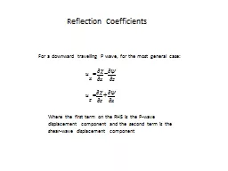
/
Reflection Coefficients For a downward travelling P wave, for the most general case: Reflection Coefficients For a downward travelling P wave, for the most general case:

Reflection Coefficients For a downward travelling P wave, for the most general case: - PowerPoint Presentation

olivia-moreira
olivia-moreira . @olivia-moreira
Follow
377 views
Uploaded On 2018-01-31

Reflection Coefficients For a downward travelling P wave, for the most general case: - PPT Presentation

Where the first term on the RHS is the Pwave displacement component and the second term is the shearwave displacement component Reflection Coefficients and where both shear stress and as well as normal stress is continuous across the boundary ID: 626623

coefficients reflection case energy reflection coefficients energy case critical layer amplitude incidence boundary angle ray shift phase travels upward

Share:

Link:

Embed:

Download Presentation from below link

Download Presentation The PPT/PDF document "Reflection Coefficients For a downward t..." is the property of its rightful owner. Permission is granted to download and print the materials on this web site for personal, non-commercial use only, and to display it on your personal computer provided you do not modify the materials and that you retain all copyright notices contained in the materials. By downloading content from our website, you accept the terms of this agreement.


Presentation Transcript

Slide1

Reflection Coefficients

For a downward travelling P wave, for the most general case:

Where the first term on the RHS is the P-wave displacement component and the second term is

the shear-wave

displacement componentSlide2

Reflection Coefficients

and where both shear stress,

and as well as normal stress is continuous across the boundary:Slide3

Reflection Coefficients

When all these conditions are met and for the special case of normal incident conditions, we have that Zoeppritz’s

equations are:

On occasions these equations will not add up to what you might expect…!Slide4

Reflection CoefficientsSlide5

Reflection CoefficientsSlide6

Reflection CoefficientsSlide7

Reflection CoefficientsSlide8

Reflection CoefficientsSlide9

Reflection Coefficients

What happens when we have a complete reflection with a 180 degree phase shift, as we might have when a ray in water travels upward toward a free surface and reflects completely at the interface?Slide10

Reflection Coefficients

What happens when we have a complete reflection with a 180 degree phase shift, as we might have when a ray in water travels upward toward a free surface and reflects completely at the interface?

We know that in this case:Slide11

Reflection Coefficients

What happens when we have a complete reflection with a 180 degree phase shift, as we might have when a ray in water travels upward toward a free surface and reflects completely at the interface?

We know that in this case:

But,

What must: Slide12

Reflection Coefficients

What happens when we have a complete reflection with a 180 degree phase shift, as we might have when a ray in water travels upward toward a free surface and reflects completely at the interface?

We know that in this case:

But,

So,Slide13

Reflection Coefficients

Z+

Z-

X+

In layer 1, just above the boundary, at the point of incidence:

layer 1

layer 2

Briefly, how to consider displacements at interfaces using potentials, when mode conversion occurs:Slide14

Reflection Coefficients

Z+

Z-

X+

layer 1

layer 2

Briefly, how to consider displacements at interfaces using potentials, when mode conversion occurs:

In layer 2, just below the boundary, at the point of incidence:Slide15

Reflection Coefficients

So, if we consider that (1) stresses as well as (2) displacements are the same at the point of incidence whether we are in the top or bottom layer the following must hold true so that (3) Snell’s Law holds true:Slide16

Reflection Coefficients

We get the general case of all the different types of reflection and transmission (refraction or not) coefficients at all angles of incidence :Slide17

Variation of Amplitude with angle (“AVA”) for the

fluid-over-fluid

case (NO

SHEAR

WAVES)

(Liner, 2004; Eq. 3.29,

p.68; ~

Ikelle

and Amundsen, 2005, p. 94)

Reflection CoefficientsSlide18

What occurs at and beyond the critical angle?

Reflection CoefficientsSlide19

FLUID-FLUID

case

What occurs at the critical angle?

(Liner, 2004; Eq. 3.29,

p.68; ~

Ikelle

and Amundsen, 2005, p.94)

Reflection CoefficientsSlide20

Reflection Coefficients at all

angles: pre-

and post-critical

Matlab Code

Reflection Coefficients

Case:

Rho: 2.2 /1.8

V: 1800/2500Slide21

NOTES: #1

At the critical angle, the real portion of the RC goes to 1. But, beyond it drops. This does not mean that the energy is dropping. Remember that the RC is complex and has two terms. For an estimation of energy you would need to look at the square of the amplitude. To calculate the amplitude we include

both the imaginary and real

portions of the RC.

Reflection CoefficientsSlide22

NOTES: #2

For the

critical ray,

amplitude is maximum (=1) at critical angle.

Post-critical angles also have a maximum amplitude because all the energy is coming back as a reflected wave and no energy is getting into the lower layer

Reflection CoefficientsSlide23

NOTES: #3

Post-critical angle rays will experience a phase shift, that is the shape of the signal will change.

Reflection CoefficientsSlide24

Energy Coefficients

We saw that for reflection coefficients :

For the energy coefficients at

normal incidence :Slide25

Energy Coefficients

We saw that for reflection coefficients :

For the energy coefficients at

normal incidence :

The sum of the energy is expected to be conserved across the boundarySlide26

Amplitude versus Offset (AVO)

Zoeppritz’s equations can be

simplied if we assume that the following ratios are much smaller than 1:

For example, the change in velocities across a boundary is very small when compared to the average velocities across the boundary; in other words when velocity variations occur in small increments across boundaries… This is the ASSUMPTION Slide27

Amplitude versus Offset (AVO)

If the changes across boundaries are relatively small, then we can make a lot of approximations to simplify the reflection and transmission coefficients: