/
Vacuum technologies of existing and future GW interferometers Vacuum technologies of existing and future GW interferometers

Vacuum technologies of existing and future GW interferometers - PowerPoint Presentation

partysilly
partysilly . @partysilly
Follow
343 views
Uploaded On 2020-06-23

Vacuum technologies of existing and future GW interferometers - PPT Presentation

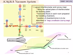
Aspera Technology Forum Darmstadt 1314 March 2012 CBradaschia GParguez A Pasqualetti EGO Pisa Italy Virgo Experiment GW RESEARCH with INTERFEROMETERS Ground Based GWs alternately squeeze and stretch space in two perpendicular directions ID: 784271

mirror 2012 technology aspera 2012 mirror aspera technology march forum chambers virgo darmstadt pumps 3rd vacuum ligo mbar design

Share:

Link:

Embed:

Download Presentation from below link

Download The PPT/PDF document "Vacuum technologies of existing and futu..." is the property of its rightful owner. Permission is granted to download and print the materials on this web site for personal, non-commercial use only, and to display it on your personal computer provided you do not modify the materials and that you retain all copyright notices contained in the materials. By downloading content from our website, you accept the terms of this agreement.


Presentation Transcript

Slide1

Vacuum technologies of existing and future GW interferometers

Aspera Technology ForumDarmstadt, 13-14 March 2012

C.Bradaschia, G.Parguez, A.

Pasqualetti E.G.O. Pisa, Italy

Virgo Experiment

Slide2

GW RESEARCH with INTERFEROMETERS (Ground Based)

GW’s alternately squeeze and stretch space in two perpendicular directions

To detect GWs , the laser interferometers allow to monitor the relative displacements of free masses (mirrors

):

order of 1E-18m (frequency band 10Hz-10KHz) for mirrors at km of distance

Optics and laser beam are under vacuum to avoid several disturbances (index statistical fluctuation, gas damping , acoustic effects)

+

L

-

L

3rd

ASPERA Technology Forum

-

Darmstadt, March 2012

Slide3

GW ground based INTERFEROMETERS, present and future

LCGT

under construction

GEO600

ET = third generation European interferometer is under design (EU design study completed)

www.et-gw.eu

Present detectors are now being updated to increase their sensitivity x 10

3rd

ASPERA Technology Forum

-

Darmstadt, March 2012

Slide4

Advanced Detectors

Stop data taking and start costruction works in progressFinalization and procurement of new parts 2012-2013Inizio funzionamento Advanced Virgo 2015ET

design study achieved (funded by EU - FP7)

done, 2011

tecnichal design, R&D on

technologies

2012-2020construction (1 detector ) 2020-2026end of commissioning 2030

Evolution timeschedule

3rd

ASPERA Technology Forum

- Darmstadt, March 2012

Slide5

VACUUM SYSTEM LAYOUT

Main vacuum chambers (I and II generation detectors):

Tubes:

Contain just the laser beam

Lenght 2 x 600m to 4km

diameter = up to 1.2m

Volume up to 9000 m

3

!

10

-7 mbar for initial detectos10-9

for advanced ones (Noise scales as e P )Mirror chambers

Order of 10 chambers (one per principal mirror) several m3 each

Contaminants free (optics degratation)Large valves 1m diameter typical , to isolate , vent and access the mirror chambersHV or low vacuum chambers for optical benches and other parts3rd ASPERA Technology Forum -

Darmstadt, March 2012

Slide6

Inside a Mirror chamber:

a principal mirror with its positioning controls (Virgo suspended payload).

Glass baffles covers the

chambers

walls to absorb scattered light.

Not evident, equipment for thermal compensation of mirror curvature

Mirror chambers are normally baked once before optic inserption for cleaning purposes, and not baked with optics in – situ .

periodically

accessed

by personnel for tunings of equipment

3rd ASPERA Technology Forum - Darmstadt, March 2012

Slide7

‘Central

hall’

:

mirror

chambers design depends on the seismic attenuation system

2m diameter in average, up to 11m high

Normally metal sealed (or double o-ring), single o-ring for HV compartments

raw material: 304L (316L)

Can incorporate order of 100 viewports in total (custom and standard design, BK-7, ZnSe, FS) and signals feedthroughs

3rd

ASPERA Technology Forum

- Darmstadt, March 2012

Slide8

The end mirror seen from the tube (Virgo)

tube contains just baffles (st. steel) to mitigate light scattering from pipe walls and the laser beamThe gas load from an entire baked tube (hydrogen) is normally less than from unbaked mirror chambers (recharged at each venting). Baking of a km tube is an expensive and time consuming effort preserved with large cryogenic pumps

(LIGO

, and AdV) condensing water vapor on 77K surfaces.

3rd

ASPERA Technology Forum

-

Darmstadt, March 2012

Slide9

Much larger infrastructures

will

be required by

ET

1 detector = low frequency

cryo

-interferometer + high frequency interferometer

Slide10

Some figures

for

ET

(

single detector configuration)

Pressure level in the tubes 10

-10

mbar

view of the central hall

Slide11

Dust and contamination would increase scattering and absorption of optical surfaces

When vented, mirror and optical chambers become sort of ‘clean room’ (class 100 normally) thanks to filtered air flushing inside. Staged cleanliness control: they are opened only vs permanent or portable clean rooms (picture

by LIGO

) and also the general building cleanliness is cured

After

the 8 years of service we have not experienced degradations of the core optics, apart from dust (Virgo) . Some point absorbers have been found , their origin is under study

Absorption map of

NI

mirror, Ø300mm,

average <2 ppm

3rd

ASPERA Technology Forum

- Darmstadt, March 2012

Slide12

HV compartments, with lower vacuum reqts, can contain:

Tens of m of Viton seals, a few km of cables, tens of motors, gears and complex metallic parts, magnets, tens of m

2

of kapton and

teflon,

epoxy adhesives...

Normally are glass-separated (viewports with aperture of 350mm or more) or through differential pumping or cryogenic trap as a precaution against contaminationCleaning facilities on site: large ultrasonic baths, ultrapure water equipment, baking ovens

Slide13

Tubes technologies

Raw material 304L, 1000 tons (Virgo or LIGO) 1.2m - 0.6 m diameterTwo designs:_ Plain wall (3.2 or

4 mm

thick), stiffeners and bellows

_ corrugated

wall

, 0.8mm thick (316L, GEO600)Assembled joining modules from 5 to 20m lengthJoints welded in-situ: butt (LIGO) or lip (Virgo, GEO600)

3rd

ASPERA Technology Forum

- Darmstadt, March 2012

Slide14

Tube technologies

In vacuum surface =

30000 m

2

Firing’ as outgassing reduction treatment (hydrogen) =

400°C

in air for 1-3 days, rates of a few 10

-14 mbar.l/s.cm2

@20°C Applied on raw material (LIGO) or on finished modules (Virgo )

Test procedures during assembly:

_Leak test on each module _Leak test on each single welded joint (LIGO) or on sections of assembled modules (Virgo, including bake)Baking in vacuum: modules are yhen wrapped with thermal insulation and heated DC joule effect up to 150C for some days

ET challenges about tubes

:Economics Assembly underground in narrow spaceTests, repairs and quality controlsBaking (heat exhaust, pseudo valves)3rd ASPERA Technology Forum

- Darmstadt, March 2012

Slide15

Pumping system requirements:

main chambers have a complete pumping system to go from atmosphere to specified vacuum level Oil free pumps are used, against contamination risk Low acoustic / seimic / emagnetic emissions to not perturb (pumps drivers included)

Long running without frequent maintenance needs to accomplish long data taking

Ion / TSP / cryogenic (liquid bath) pumps

or magnetic bearings turbo-pumps

are normally used in data taking phase

(here 2 x 2500 l/s N

2

Ion pumps - LIGO)

An example of statistic (Virgo)

25 Dry r

oughing/backing pumps

7 + 16

Turbo-molecular pumps28 Auxiliary Ion pumps38 Titanium sublimation pumps

20 Residual gas analyzers221 Angle valves111 Gate valves (size up to 250mm or similar)

4+6 Large gate valve 1m to 400mm diameter150 Pressure gauges

Slide16

Thanks to the large tube conductance, pumping stations are a few (Virgo)

Slide17

Pumping system details

Cryogenic pump <= 20K under

evaluation

(with low seismic/acoustic noise ) order of 5000l/s for instance, to pump

water and residual

air

down to 10

-9

mbar

shortening recovery times of frequently vented chambers

Mechanical vibrations: (100-1000Hz) the magnetic turbomolecular pumps are normally installed with bellows while the backing pumps (25 Hz) are displaced far away or run intermittently

Control system SW & HW becoming more integrated with experiment; pumps and gauges permanently monitored also to check possible coeherences = disturbances

1 m

3rd ASPERA Technology Forum - Darmstadt, March 2012

Slide18

Slide19

Slide20

IVC 10

-8

mbar

HV 10

-6

mbar

UHV 10

-9

mbar

Anti-sismic Suspension

Conductance Pipes

Thin Kapton Diaphrams

Mirror