/
Design & construction of a Design & construction of a

Design & construction of a - PowerPoint Presentation

phoebe-click
phoebe-click . @phoebe-click
Follow
444 views
Uploaded On 2017-05-28

Design & construction of a - PPT Presentation

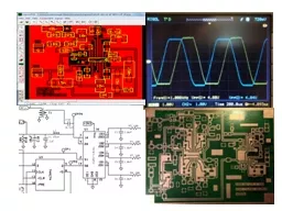
phasing receiver by Nick Kennedy WA5BDU 4SQRPs OzarkCon April 2 2016 Branson MO Things to cover in 50 minutes What do I mean by phasing receiver Current proponents and designs ID: 553551

pass design gain filter design pass filter gain amp phasing detector receiver tayloe audio pole stage network preamp 100

Share:

Link:

Embed:

Download Presentation from below link

Download Presentation The PPT/PDF document "Design & construction of a" is the property of its rightful owner. Permission is granted to download and print the materials on this web site for personal, non-commercial use only, and to display it on your personal computer provided you do not modify the materials and that you retain all copyright notices contained in the materials. By downloading content from our website, you accept the terms of this agreement.


Presentation Transcript

Slide1
Slide2

Design & construction of a

phasing receiverby Nick Kennedy, WA5BDU

4SQRP’s OzarkCon - April 2, 2016 Branson, MOSlide3

Things to cover in 50 minutes …

What do I mean by “phasing receiver”?Current proponents and designsMethods of generating the I & Q signals

Quadrature detector plus DSP or all analog?Construction – my intro to toner transferDesign tools – all-pass and selectivity, board layout, circuit analysis (LTspice)

My approach and resultsSlide4

Phasing receiver?

Put simply, it’s a direct conversion receiver that uses phasing techniques to eliminate the image or opposite sideband.There’s a direct mixing to audio at the front end, so the remaining circuits are all audio.

The down conversion gives two audio channels 90 degrees apart. A second 90 degree shift eliminates one sideband and reinforces the other. This may occur in DSP or analog circuits.Slide5

Who’s who in phasing receivers?

Rick Campbell KK7B with the R2 & R2Pro and articles in EMRFD and elsewhere. Prefers a single-band, analog approach.Dan Tayloe N7VE, developer of the Tayloe Detector & designer of the NORCAL NC2030.

Don Huff, W6JL, on the air evangelist for the phasing receiver design. Check out his QRZ page.Slide6
Slide7

A tiny bit of theory

LO > RF

RF > LOSlide8
Slide9

All-pass network

QuadNet

by TonneSoftware.com

Slide10

All-pass network

QuadNet will do the design or analyze your design and output the circuit for LTspice to pick up

You can multiply C’s and divide R’s by the same number to scale to your in-stock componentsYou can also swap the shunt R and series C positions of

QuadNet

, to work better with single supply design

With more sections than shown, you reach diminishing results due to required tolerances. Use precision R and measure capacitors, model actual values to predict actual performance.Slide11
Slide12

Phase shift from all-pass networkSlide13

Filters & Gain

Tools like TI’s FilterPro

simplify the filter design processExperts say keep Q and group delay low to avoid ringingAn end-to-end gain of about 100 dB is a typical goal for the entire receiver. That would raise 1

uV

at the antenna to

100 mV at the phones.

I opted for a 2400 Hz 8-pole lowpass filter that’s always in line and a 600 Hz 6-pole lowpass filter for CW that can be switched to be in series with the 8-pole filter.

A SCAF filter with tunable BW and center frequency would also be a good option.Slide14
Slide15
Slide16

FilterProSlide17

Gain table

Stage

Gain

Notes

RF preamplifier

None yet

Tayloe detector

36 dB

Post detector gain stage (HPF)

13 dB

Removed

Phase adjustment

6 dB

All-pass networks

0 dB

High-pass filter

12 dB

Measured

here

56 dB

Gain stage

6

dB

Was

20 dB, reduced …

Low-pass filter 2400 Hz

12 dB

AN6123 AGC or op-amp

24 dB

Here:

96

less preamp

Audio power amplifier

0 dB followers for phones, 12 dB gain speaker

amplifierSlide18
Slide19

Another phase shifting techniqueSlide20
Slide21

DDS chip with quadrature outputsSlide22

Toner transfer board

fabAllowed me to increase the complexity of my projects

I started with K7QO’s Muppet videos on YouTubeRequires a Laser printer ($60) laminator ($50 - $100)I use the special

fab

-in-a-box paper, but others use regular photo paper. The process works great!

ExpressPCB

is the software of choice to produce the layout

I have a personal preference for SMT over leaded. Size 1206 or 0805 parts and SOIC aren’t hard.Slide23

From design to physical …Slide24

Design trade-offs, missing bits and other notes

This design allows for all band (80-10) coverage, but requires the 4x VFO

What about a preamp? Sensitivity is good as-is, but I agree a switchable preamp would be helpful at times and do expect to try some designs. Maybe an attenuator too.

Where’s the front-end filtering?

The Tayloe detector has very high overload tolerance. I’ve heard a bit of AM-BC and SW-BC breakthrough at times, with my boards exposed on the bench. But not bad overall. I have used an external HPF for a local AM station on 610 kHz.

Well, how does it sound?

It sounds great to me. Mostly the absence of ringing. I have some background hiss, especially in the wide BW position. More tweaking could reduce that.