/
Sparkfun  Electronics ATtiny85 Arduino Quick Reference Sheet Sparkfun  Electronics ATtiny85 Arduino Quick Reference Sheet

Sparkfun Electronics ATtiny85 Arduino Quick Reference Sheet - PowerPoint Presentation

roberts
roberts . @roberts
Follow
65 views
Uploaded On 2023-11-12

Sparkfun Electronics ATtiny85 Arduino Quick Reference Sheet - PPT Presentation

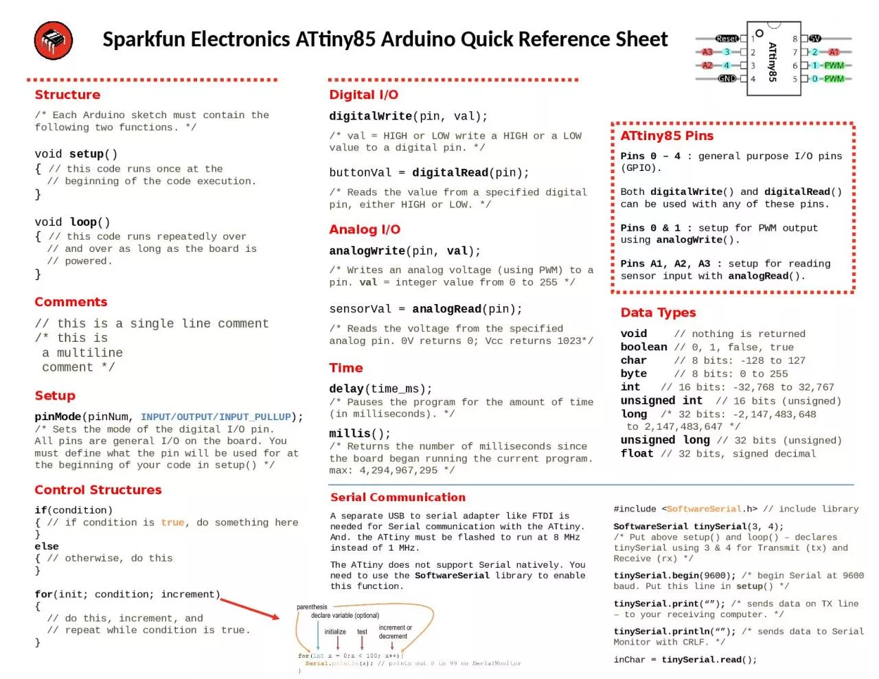
Structure Each Arduino sketch must contain the following two functions void setup this code runs once at the beginning of the code execution void loop this code runs repeatedly over ID: 1031631

bits pin pins setup pin bits setup pins input val unsigned digital code time serial condition high board program

Share:

Link:

Embed:

Download Presentation from below link

Download Presentation The PPT/PDF document "Sparkfun Electronics ATtiny85 Arduino Q..." is the property of its rightful owner. Permission is granted to download and print the materials on this web site for personal, non-commercial use only, and to display it on your personal computer provided you do not modify the materials and that you retain all copyright notices contained in the materials. By downloading content from our website, you accept the terms of this agreement.


Presentation Transcript

1. Sparkfun Electronics ATtiny85 Arduino Quick Reference SheetStructure/* Each Arduino sketch must contain the following two functions. */void setup(){ // this code runs once at the // beginning of the code execution. }void loop(){ // this code runs repeatedly over // and over as long as the board is // powered.}Comments// this is a single line comment/* this is a multiline comment */SetuppinMode(pinNum, INPUT/OUTPUT/INPUT_PULLUP);/* Sets the mode of the digital I/O pin. All pins are general I/O on the board. You must define what the pin will be used for at the beginning of your code in setup() */Control Structuresif(condition){ // if condition is true, do something here }else{ // otherwise, do this}for(init; condition; increment){ // do this, increment, and // repeat while condition is true.}Digital I/OdigitalWrite(pin, val);/* val = HIGH or LOW write a HIGH or a LOW value to a digital pin. */buttonVal = digitalRead(pin);/* Reads the value from a specified digital pin, either HIGH or LOW. */Analog I/OanalogWrite(pin, val); /* Writes an analog voltage (using PWM) to a pin. val = integer value from 0 to 255 */sensorVal = analogRead(pin);/* Reads the voltage from the specified analog pin. 0V returns 0; Vcc returns 1023*/Timedelay(time_ms);/* Pauses the program for the amount of time (in milliseconds). */millis();/* Returns the number of milliseconds since the board began running the current program. max: 4,294,967,295 */Serial CommunicationA separate USB to serial adapter like FTDI is needed for Serial communication with the ATtiny. And. the ATtiny must be flashed to run at 8 MHz instead of 1 MHz. The ATtiny does not support Serial natively. You need to use the SoftwareSerial library to enable this function.ATtiny85 PinsPins 0 – 4 : general purpose I/O pins (GPIO). Both digitalWrite() and digitalRead() can be used with any of these pins.Pins 0 & 1 : setup for PWM output using analogWrite().Pins A1, A2, A3 : setup for reading sensor input with analogRead().Data Typesvoid // nothing is returnedboolean // 0, 1, false, truechar // 8 bits: -128 to 127byte // 8 bits: 0 to 255int // 16 bits: -32,768 to 32,767 unsigned int // 16 bits (unsigned)long /* 32 bits: -2,147,483,648 to 2,147,483,647 */unsigned long // 32 bits (unsigned)float // 32 bits, signed decimalATtiny85#include <SoftwareSerial.h> // include librarySoftwareSerial tinySerial(3, 4); /* Put above setup() and loop() – declares tinySerial using 3 & 4 for Transmit (tx) and Receive (rx) */tinySerial.begin(9600); /* begin Serial at 9600 baud. Put this line in setup() */tinySerial.print(“”); /* sends data on TX line – to your receiving computer. */tinySerial.println(“”); /* sends data to Serial Monitor with CRLF. */inChar = tinySerial.read();

2. SparkFun Electronics ATtiny85 Arduino Quick Reference SheetStructure/* Each Arduino sketch must contain the following two functions. */void setup(){ // this code runs once at the // beginning of the code execution. }void loop(){ // this code runs repeatedly over // and over as long as the board is // powered.}Comments// this is a single line comment/* this is a multiline comment */SetuppinMode(pinNum, INPUT/OUTPUT/INPUT_PULLUP);/* Sets the mode of the digital I/O pin. All pins are general I/O on the board. You must define what the pin will be used for at the beginning of your code in setup() */Control Structuresif(condition){ // if condition is true, do //something here }else{ // otherwise, do this}for(init; condition; increment){ // do this}Digital I/OdigitalWrite(pin, val);/* val = HIGH or LOW write a HIGH or a LOW value to a digital pin. */buttonVal = digitalRead(pin);/* Reads the value from a specified digital pin, either HIGH or LOW. */Analog I/OanalogWrite(pin, val); /* Writes an analog value to a pin.val = integer value from 0 to 255 */sensorVal = analogRead(pin);/* Reads the value from the specified analog pin. */Timedelay(time_ms);/* Pauses the program for the amount of time (in milliseconds). */delayMicroseconds(time_us);/* Pauses the program for the amount of time (in microseconds). */millis();/* Returns the number of milliseconds since the board began running the current program. max: 4,294,967,295 */micros();/* Returns the number of microseconds since the board began running the current program. max: 4,294,967,295 */ATtiny85 PinsPins 0 – 4 are all general purpose I/O pins (GPIO). Both digitalWrite() and digitalRead() can be used with any of these pins.Pins 0 & 1 are setup for PWM output using analogWrite().Pins A1, A2, A3 are setup for reading sensor input with analogRead().Data Typesvoid // nothing is returnedboolean // 0, 1, false, truechar // 8 bits: ASCII characterbyte // 8 bits: 0 to 255int // 16 bits: -32,768 to 32,767 unsigned int // 16 bits (unsigned)long /* 32 bits: -2,147,483,648 to 2,147,483,647 */unsigned long // 32 bits (unsigned)float // 32 bits, signed decimalConstantsHIGH \ LOWINPUT \ OUTPUT \ INPUT_PULLUPtrue \ false/* The ‘for’ statement is used to repeat a block of statements enclosed in curly braces. An increment counter is usually used to increment and terminate the loop. */ATtiny85v2

3. analogWrite([0/1], value);analogRead([A1/A2/A3);digitalWrite([0-4], [HIGH\LOW]);digitalRead([0-4]);delay(time_ms);pinMode(pin, [INPUT/OUTPUT/INPUT_PULLLUP);analogWrite(pin, value);Arduino ATtiny85 Quick Reference SheetArduino colors:dark green: 94, 109, 3orange: 233, 115, 0blue: 0, 150, 189grey: 67, 79, 84

4. for(int x = 0;x < 100; x++){ Serial.println(x); // prints out 0 to 99 on SerialMonitor}parenthesisdeclare variable (optional)initializetestincrement or decrement