/
Pinhole Cameras Pinhole Cameras

Pinhole Cameras - PDF document

tatiana-dople
tatiana-dople . @tatiana-dople
Follow
401 views
Uploaded On 2016-07-09

Pinhole Cameras - PPT Presentation

x2013 
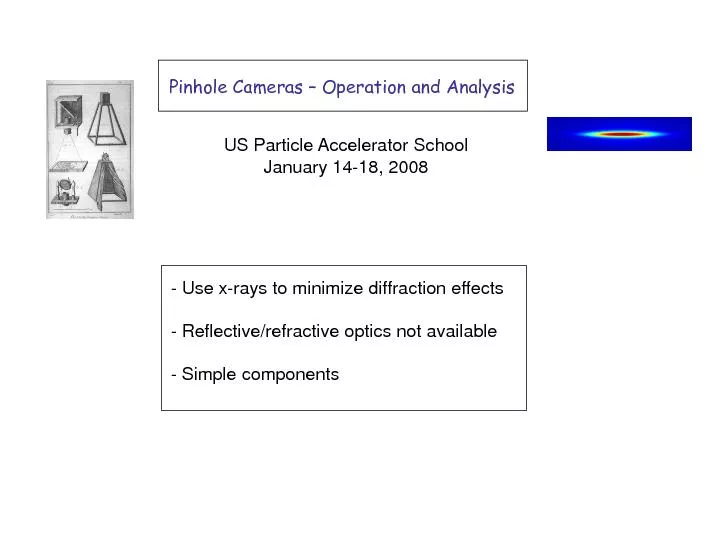
Operation and Analysis Use x rays to minimize diffraction effects Reflectiverefractive optics not available Simple components US Particle Accelerator School January 14 18 2008 Ca ID: 397691

– Operation and Analysis - Use x - rays

Share:

Link:

Embed:

Download Presentation from below link

Download Pdf The PPT/PDF document "Pinhole Cameras" is the property of its rightful owner. Permission is granted to download and print the materials on this web site for personal, non-commercial use only, and to display it on your personal computer provided you do not modify the materials and that you retain all copyright notices contained in the materials. By downloading content from our website, you accept the terms of this agreement.


Presentation Transcript

Pinhole Cameras – Operation and Analysis - Use x - rays to minimize diffraction effects - Reflective/refractive optics not available - Simple components US Particle Accelerator School January 14 - 18, 2008 Camera Obscura object image pinhole d 1 d 2 X - ray Pinhole Camera - Schematic DIAMOND circa 2005 SPEAR circa 1975 SPEAR3 Pinhole, Filters, YaG Screen and Camera  Electron beam distribution where 1. Horizontal Plane What does the Pinhole Camera See?  Photon beam distribution (new Twiss, new ellipse) Searchlight sweeping across pinhole integrates over x’ (simple result) fit to Gaussian, compute e o BESSY - II Pinhole Array (Peatmann and Holldack) Constant Image Intensity Finite beam divergence SPEAR3 Example – three different operational modes x - position [ m m] x - position [ m m] intensity [au] intensity [au] Measurement Theory 2. Vertical Plane What does the Pinhole Camera See? - Sweeping searchlight no longer integrates over angles - Pinhole projected onto source casts a ‘shadow’ in phase space: position [ m m] angle [ m rad] at the screen (neglecting diffraction) What size pinhole? s If the pinhole is large, ray - optic ‘spread’ dominates d 1 d 2 w If the pinhole is small, diffraction dominates... Evaluating the Source Size L 1 Source – pinhole 2.34 m L 2 Pinhole - screen 1.2 m Demagnification 1.95:1 W pinhole size 63 m m ~ 40 m m point source screen aperture (spherical waves) (Huygen’s wavelets) (field superposition) Diffraction Effects – monochromatic beam Point Source Diffraction (cont’d) retangular aperture - surface integral is separable field integral over pinhole aperture expand ‘r’ and ‘s’ to 2 nd order - the field integrals look like Distributed Source Field Pattern is for a point source  Integrate again over the source distribution where (Gaussian distribution)  Jack reduced the double integral to a single integral A, B and C are physical system parameters emittance image ‘Polychromatic’ Diffraction  Integrate intensity pattern over photon spectrum spectrum at screen dN/dE : Photons/sec/keV Sands - 121 C. Limborg - SSRL Putting it all together... fresnel.m valid from geometric to diffraction regimes A y =40 micron (optimum) A y =5 micron (diffraction) A y =250 micron (geometric) 143 m m 250 m m 78 m m J. Bergstrom - CLS Application to measurement spot size on screen magnification, wave optics, chromatics electron beam source size hardening of the spectrum 0.1% coupling SPEAR3: M=0.6, w=30 m m, 8keV Summary - Pinhole cameras effective in the x - ray regime - System construction fairly straight - forward - Power loading considerations - Optimize aperture size - Data analysis relies on comparison of model with measurement fresnel.m - Effective for measuring small spot sizes