/
PUME is a digital input/output module used as an auxiliary input/outpu PUME is a digital input/output module used as an auxiliary input/outpu

PUME is a digital input/output module used as an auxiliary input/outpu - PDF document

titechas
titechas . @titechas
Follow
343 views
Uploaded On 2020-11-19

PUME is a digital input/output module used as an auxiliary input/outpu - PPT Presentation

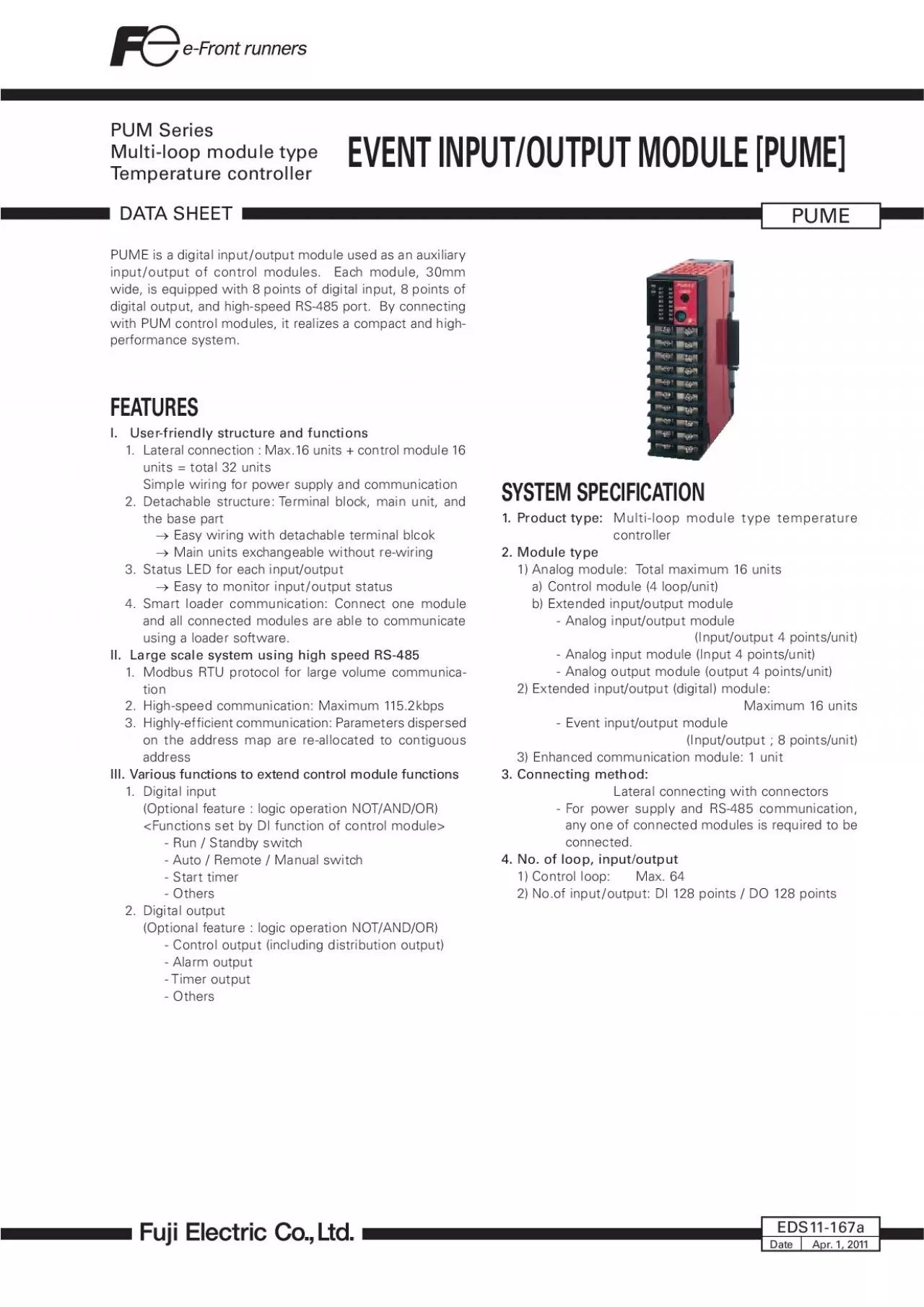
PUME DATA SHEET EDS11167aApr 1 2011 SYSTEM SPECIFICATION1 Product type Multiloop module type temperature 2 Module type1 Analog module Total maximum 16 unitsa Control module 4 loopunitb E ID: 817334

output 100 bit data 100 output data bit operation 0000 module input event type0 1111 option0 area limit0 and0000

Share:

Link:

Embed:

Download Presentation from below link

Download Pdf The PPT/PDF document "PUME is a digital input/output module us..." is the property of its rightful owner. Permission is granted to download and print the materials on this web site for personal, non-commercial use only, and to display it on your personal computer provided you do not modify the materials and that you retain all copyright notices contained in the materials. By downloading content from our website, you accept the terms of this agreement.


Presentation Transcript

PUME is a digital input/output module us
PUME is a digital input/output module used as an auxiliary input/output of control modules. Each module, 30mm wide, is equipped with 8 points of digital input, 8 points of digital output, and high-speed RS-485 port. By connecting with PUM control modules, it realizes a compact and high-performance system.FEATURESI. User-friendly structure and functions 1. Lateral connection : Max.16 units + control module 16 units = total 32 units Simple wiring for power supply and communication 2. Detachable structure: Terminal block, main unit, and Easy wiring with detachable terminal blcok Main units exchangeable without re-wiring 3. Status LED for each input/output Easy to monitor input/output status 4. Smart loader communication: Connect one module and all connected modules are able to communicate using a loader software.II. Large scale system using high speed RS-485PUMEDATA SHEETEDS11-167aApr. 1, 2011SYSTEM SPECIFICATION1. Product type: Multi-loop module type temperature 2. Module type1) Analog module: Total maximum 16 unitsa

) Control module (4 loop/unit)b) Extende
) Control module (4 loop/unit)b) Extended input/output module- Analog input/output module - Analog input module (Input 4 points/unit)- Analog output module (output 4 points/unit)2) Extended input/output (digital) module: Maximum 16 units- Event input/output module 3. Connecting method:PUME2SPECIFICATION1. General speci“ cation(1) Power supply: 24V DC ±10%(2) Power consumption:.2 W (1(1s applied] or more (500V DC)(4) Withstand voltage:Power diital input diital 1000V AC 1 min. (diital input between bloital output between blo 500V AC 1 min.(5) Applied standards:, RoHS diretive[Pendin for UL, C-UL markin point (4 point Voltaonta 24V DC, input impedane approx. 4.7kment: 16 to 26.4V DCment: 0 to 5V DC 200m Funir- NOT/AND/OR lo operation, Lat point (4 point Sele to model type a) Relay onta- Contatruture: SPST onta- Contaity: 220V AC/ulation: Funulation with inter-b) Tran- Ratin: 24V DC, 100mA (Reidual voltae when power ON: 1.5V DC or leulation: Funulation with inter- Control output/Event output tion, NOT/AND/OR lo operation, LatRS-4(2)

No. of port: (3) Communication, synchro
No. of port: (3) Communication, synchro method: Two-wire, half-duplex, a9.6k, 19.2k, .4k, 115.2kbp or le), 250m (115.2kbp(6) Recommended cable: KPEV-SB 0.5q-equivalent unit (malave) if any module other than PUM are inlaveData bit; , parity; even / odd / none(9) Protocol: RTU (10) Insulation: No ination Funulation with any other in-put/output4.2 Loader communication (RS-232C) interfaceRS-2(2) No. of port: (3) Communication, synchro method: Half-duplex, a19.2kbp (“ xed)Data bit , no parity(6) Protocol: RTU /jaa(Common cable with PXG, PXH)(8) Insulation: No insulation with RS-4Funulation with any other in-put/output5. Display, con“ guration5.1 Display Statu diplay LED × 2 point + 16 point(2) Display contents: RUN/FAULT, RS-45 TX/RX, Input × point5.2 Setting device(1) Setting device: Rotary SW × 1 (2) Set contents: RS-45 Station No. (Station No.= ettin value + 17)6. Power outageOuta or le ; no impa(2) Operation after power outage: Start from the “tart)(3) Memory backup: Nonvolatile memory (EEPROM)No. of update ; 100,0007. Self diagno

sisDiagnosis method: Proram error monito
sisDiagnosis method: Proram error monitorin by wat(1) Installation method: or mountin with Mrew in0 (W) × 100 (H) × (ex terminal over and projeted (3) Weight: Approx. 200 3ital input / diital output:Detarew × 20 terminal- Power Terminal bloe part rew × 2 terminalPower i- RS-4Terminal bloe part rew × terminalRS-4ted via in - Loader /jaa(5) Case material: Polyphenylene oxide ame retardant rade : UL94V-0 equiva-Terminal, ba(7) Protection- Body: IP20 (ventilation on the top and the bot-- Terminal: IP00 over i available a an option(1) Ambient temperature*: -10 to 50°C* Ambient temperatureŽ i the tempera-ture underneath the ide abinet where intalled. (2) Ambient humidity: (non (3) Vibration: 10 to 70Hz, 9. (1G) or le10. Transporting, storage condition (packing con- -20 to 60°C(2) Ambient humidity: 90%RH or le (no (3) Vibration: 10 to 70Hz, 9. (1G) or le(4) Shock: 294m/11. Packing listTemperature controller: 1unit 1 opy12. Loader softwareFree download from Fuji Ele Sy HP (http://www.“/index.(2) Recommended operating environmentPC: DOS/V (

PC-AT OS: Window XP (operation onfirmed
PC-AT OS: Window XP (operation onfirmed in JapaneRAM: 256M byte or moreFree e on the hardware: 500M byte or moreplay reolution: 1024 × 76 or overSerial interfae: RS-2 (without RS-2onverter Via loader interfae on the front fae of the module able available from Fuji i required) or via RS-4PUMECODE SYMBOLSYMBOLS[Accessories][Table 1] Insulation block diagramDescriptionModuletyp&#x-279;&#x.300;e Eventinput/outputmodule [Dipoint/DopointOutputtype&#x-280;&#x.700; Tranitoropenolletor(ink)outputRelayontatoutputperationmanua&#xO-5.; l Japane9PUMYYgitRS-45terminatinDINrailmountinendplateSideonnetinterminalover(riht&left1Frontfarewterminalovertinable(RS-22C)PUMZDescriptionPowerommuniationportRS-4ommuniationportFuntionalinulation(1000VAC)Funtionalinulation(500VAC)5OUTLINE DIAGRAM (Unit : mm)s recommended]Front terminal cover (Option)(10)301001.5STATIONLOADERscrew M3Terminal block(at attach/detach)Hole for screw mountingTerminal screwM3PUMETERMINAL CONNECTION DIAGRAMLOADER11122221131415161718192023242526272829302425Digital input

222123Power+-21CommunicationRS485
222123Power+-21CommunicationRS485A(+)3SG4B(-)524VDC23GNDRXTXLoader interface plug (RS-232C)2.5 3-pole miniature plugDi2Di1Di4Di32930272628Di6Di5Di8Di724V DCDigital output1415121113TransistorO.C. (SINK)24V DCDo1Do2Do3Do4COM to 4Digital input5 to 81 to 4Do1Do2Do4Do3COM15121113Digital output19201718TransistorO.C. (SINK)L24V DCDo5Do6Do7Do8COM to 8Do5Do6Do8Do7COM19201718167Parameter (name)Read/write date ettin raneFatory defaultReRun/Standby h0: Run1: Standby0 (RUN)40021ital input latommand0: OFF1: Relea0 (OFF)40022ital output lat1: Relea0 (OFF)4002Parameter (name)Read/write date ettin raneFatory defaultReRS-45 Parity ettin0 (NONE)40111RS-45 Ree interval time0 to 25 (×20m)14011RS-4ion0: Read only1: Read/Write1 (R/W)40114RS-4peed0: 9.6kbp1: 19.2kbp: Forbidden4: 115.2kbp)40115ation module ted (RS4ted (RS4040116 guration parameterParameter (name)Read/write date ettin raneFatory defaultReFAULT output et value 0: HOLD0 (HOLD)40260Standby output et value0000 to Standby mode ettin0: DI=Input value, DO=S

tandby output et value1: DI=All OFF, DO=
tandby output et value1: DI=All OFF, DO=Standby output et value040270LED2 Lamp Alloation0 to 2140222PUME8Parameter (name)Read/write date ettin raneFatory defaultReDI1 Input option0 to 15 (bit data : 0000 to 1111) bit0 : LATCH bit1 : NOT bit2 : AND bit : OR0 (bit data 0000)40701 operation AND0000 to 00FF0000 operation OR0000 to 00FF0000DI2 Input option0 to 15 (bit data : 0000 to 1111)0 (bit data 0000) operation AND0000 to 00FF0000 operation OR0000 to 00FF0000 Input option0 to 15 (bit data : 0000 to 1111)0 (bit data 0000) Input lo operation AND0000 to 00FF000040711 Input lo operation OR0000 to 00FF000040712DI4 Input option0 to 15 (bit data : 0000 to 1111)0 (bit data 0000) operation AND0000 to 00FF000040715 operation OR0000 to 00FF000040716DI5 Input option0 to 15 (bit data : 0000 to 1111)0 (bit data 0000)40717 operation AND0000 to 00FF000040719 operation OR0000 to 00FF0000DI6 Input option0 to 15 (bit data : 0000 to 1111)0 (bit data 0000) operation AND0000 to 00FF0000 operation OR0000 to 00FF0000DI7 Input option0 to 15 (bit data

: 0000 to 1111)0 (bit data 0000) operati
: 0000 to 1111)0 (bit data 0000) operation AND0000 to 00FF0000 operation OR0000 to 00FF0000 Input option0 to 15 (bit data : 0000 to 1111)0 (bit data 0000) Input lo operation AND0000 to 00FF0000407 Input lo operation OR0000 to 00FF00004079Parameter (name)Read/write date ettin raneFatory defaultReDO1 Output type0: Event output0 (Event output)40401DO1 Mater module St. No.0 to 255040402DO1 Mater module Ch. No.1 to 414040DO1 BIT po0000 to 00FF0001DO1 Output option0 to 15 (bit data : 0000 to 1111) bit0 : LATCH bit1 : NOT bit2 : AND bit : OR0 (bit data 0000)DO1 Output lo operation AND0000 to 00FF0000DO1 Output lo operation OR0000 to 00FF0000DO1 S bae-100.0 to 100.0%0.040409DO1 Span-100.0 to 100.0%100.040410DO1 Proportion le1 to 120 040411DO1 Lower limit0.0 to 100.0%0.040412DO1 Upper limit0.0 to 100.0%100.04041DO1 Limit type0 to 040414DO2 Output type0: Event output0 (Event output)40415DO2 Mater module St. No.0 to 255040416DO2 Mater module Ch. No.1 to 4140417DO2 BIT po0000 to 00FF0002DO2 Output option0 to 15 (bit data : 0000 to 1111)0

(bit data 0000)40419DO2 Output lo operat
(bit data 0000)40419DO2 Output lo operation AND0000 to 00FF0000DO2 Output lo operation OR0000 to 00FF0000DO2 S bae-100.0 to 100.0%0.04042DO2 Span-100.0 to 100.0%100.040424DO2 Proportion le1 to 120 040425DO2 Lower limit0.0 to 100.0%040426DO2 Upper limit0.0 to 100.0%100.040427DO2 Limit type0 to 04042 Output type0: Event output0 (Event output)40429 Mater module St. No.0 to 2550404 Mater module Ch. No.1 to 41404 BIT po0000 to 00FF0004404 Output option0 to 15 (bit data : 0000 to 1111)0 (bit data 0000)404 Output lo operation AND0000 to 00FF0000404 Output lo operation OR0000 to 00FF0000404 bae-100.0 to 100.0%0.0404pan-100.0 to 100.0%100.0404 Proportion le1 to 120 0404 Lower limit0.0 to 100.0%0.040440 Upper limit0.0 to 100.0%100.040441 Limit type0 to 040442DO4 Output type0: Event output0 (Event output)4044DO4 Mater module St. No.0 to 255040444DO4 Mater module Ch. No.1 to 4140445DO4 BIT po0000 to 00FF000DO4 Output option0 to 15 (bit data : 0000 to 1111)0 (bit data 0000)DO4 Output lo operation AND0000 to 00FF0000DO4 Output lo operation OR0000 to 00FF

0000DO4 S bae-100.0 to 100.0%0.040451DO4
0000DO4 S bae-100.0 to 100.0%0.040451DO4 Span-100.0 to 100.0%100.040452DO4 Proportion le1 to 120 04045DO4 Lower limit0.0 to 100.0%0.040454DO4 Upper limit0.0 to 100.0%100.040455DO4 Limit type0 to 040456PUME10Parameter (name)Read/write date ettin raneFatory defaultReDO5 Output type0: Event output0 (Event output)40457DO5 Mater module St. No.0 to 25504045DO5 Mater module Ch. No.1 to 4140459DO5 BIT po0000 to 00FF0010DO5 Output option0 to 15 (bit data : 0000 to 1111)0 (bit data 0000)DO5 Output lo operation AND0000 to 00FF0000DO5 Output lo operation OR0000 to 00FF0000DO5 S bae-100.0 to 100.0%0.040465DO5 Span-100.0 to 100.0%100.040466DO5 Proportion le1 to 120 040467DO5 Lower limit0.0 to 100.0%0.04046DO5 Upper limit0.0 to 100.0%100.040469DO5 Limit type0 to 040470DO6 Output type0: Event output0 (Event output)40471DO6 Mater module St. No.0 to 255040472DO6 Mater module Ch. No.1 to 414047DO6 BIT po0000 to 00FF000040474DO6 Output option0 to 15 (bit data : 0000 to 1111)0 (bit data 0000)DO6 Output lo operation AND0000 to 00FF0000DO6 Output lo operation

OR0000 to 00FF0000DO6 S bae-100.0 to 100
OR0000 to 00FF0000DO6 S bae-100.0 to 100.0%0.040479DO6 Span-100.0 to 100.0%100.0404DO6 Proportion le1 to 120 0404DO6 Lower limit0.0 to 100.0%0.0404DO6 Upper limit0.0 to 100.0%100.0404DO6 Limit type0 to 0404DO7 Output type0: Event output0 (Event output)404DO7 Mater module St. No.0 to 2550404DO7 Mater module Ch. No.1 to 41404DO7 BIT po0000 to 00FF0000404DO7 Output option0 to 15 (bit data : 0000 to 1111)0 (bit data 0000)404DO7 Output lo operation AND0000 to 00FF0000DO7 Output lo operation OR0000 to 00FF0000DO7 S bae-100.0 to 100.0%0.04049DO7 Span-100.0 to 100.0%100.040494DO7 Proportion le1 to 120 040495DO7 Lower limit0.0 to 100.0%0.040496DO7 Upper limit0.0 to 100.0%100.040497DO7 Limit type0 to 04049 Output type0: Event output0 (Event output)40499 Mater module St. No.0 to 255040500 Mater module Ch. No.1 to 4140501 BIT po0000 to 00FF0000 Output option0 to 15 (bit data : 0000 to 1111)0 (bit data 0000) Output lo operation AND0000 to 00FF0000 Output lo operation OR0000 to 00FF0000 bae-100.0 to 100.0%0.040507pan-100.0 to 100.0%100.04050 Proportion l

e1 to 120 040509 Lower limit0.0 to 100.0
e1 to 120 040509 Lower limit0.0 to 100.0%0.040510 Upper limit0.0 to 100.0%100.040511 Limit type0 to 04051211Parameter (name)Read/write date ettin raneFatory defaultReInternal DO data area 1Event output 1: ON 0: OFF 0.00 to 100.00041001Internal DO data area 2041002Internal DO data area 04100Internal DO data area 4041004Internal DO data area 5041005Internal DO data area 6041006Internal DO data area 7041007Internal DO data area 04100Internal DO data area 9041009Internal DO data area 1004Internal DO data area 11041011Internal DO data area 12041012Internal DO data area 104101Internal DO data area 14041014Internal DO data area 15041015Internal DO data area 16041016Parameter (name)Read/write date ettin raneFatory defaultRetem FAULT tatu0000 to FFFF-0064DO ult monitor 0000 to FFFF-1002ult monitor 0000 to FFFF-1001DI terminal monitor 0000 to FFFF-100PUME                FujiElectricYourdistributor:CoultonInstrumentationLtd17SomerfordBusinessPark,Christchurch,BH233RU,UK"+44"12024