
Architecture and Hardware (ITEC582 ) Chapter 13
CB
Published · 58 slides · 0 views
1 / 1

Description
Architecture and Hardware (ITEC582 ) Chapter 13 Instruction Sets: Addressing Modes and Formats Eastern Mediterranean University School of Computing and Technology Master of Technology 2 Learning Objectives After studying this chapter, you
Related Topics
Share
Embed code
Download this presentation From Below
"Architecture and Hardware (ITEC582 ) Chapter 13" is the property of its rightful owner. Permission is granted to download and print the materials on this website for personal, non-commercial use only, and to display it on your personal computer provided you do not modify the materials and that you retain all copyright notices contained in the materials. By downloading content from our website, you accept the terms of this agreement.
Presentation Transcript
01
Architecture and Hardware (ITEC582 ) Chapter 13
Instruction Sets: Addressing Modes and Formats Eastern Mediterranean University
School of Computing and Technology
Master of Technology<br>
Instruction Sets: Addressing Modes and Formats Eastern Mediterranean University
School of Computing and Technology
Master of Technology<br>
02
2 Learning Objectives
After studying this chapter, you should be able to:
Describe the various types of addressing modes common in instruction set
Summarize the issues and trade-offs involved in designing an instruction format.
Understand the distinction between machine language and assembly language<br>
After studying this chapter, you should be able to:
Describe the various types of addressing modes common in instruction set
Summarize the issues and trade-offs involved in designing an instruction format.
Understand the distinction between machine language and assembly language<br>
03
3 In the first chapter, we focused on what an instruction set does. Specifically, we examined the types of operands and operations that may be specified by machine instructions.
This chapter turns to the question of how to specify the operands and operations of instructions. Two issues arise.
First, how is the address of an operand specified ?
Second, how are the bits of an instruction organized to define the operand addresses and operation of that instruction?<br>
This chapter turns to the question of how to specify the operands and operations of instructions. Two issues arise.
First, how is the address of an operand specified ?
Second, how are the bits of an instruction organized to define the operand addresses and operation of that instruction?<br>
04
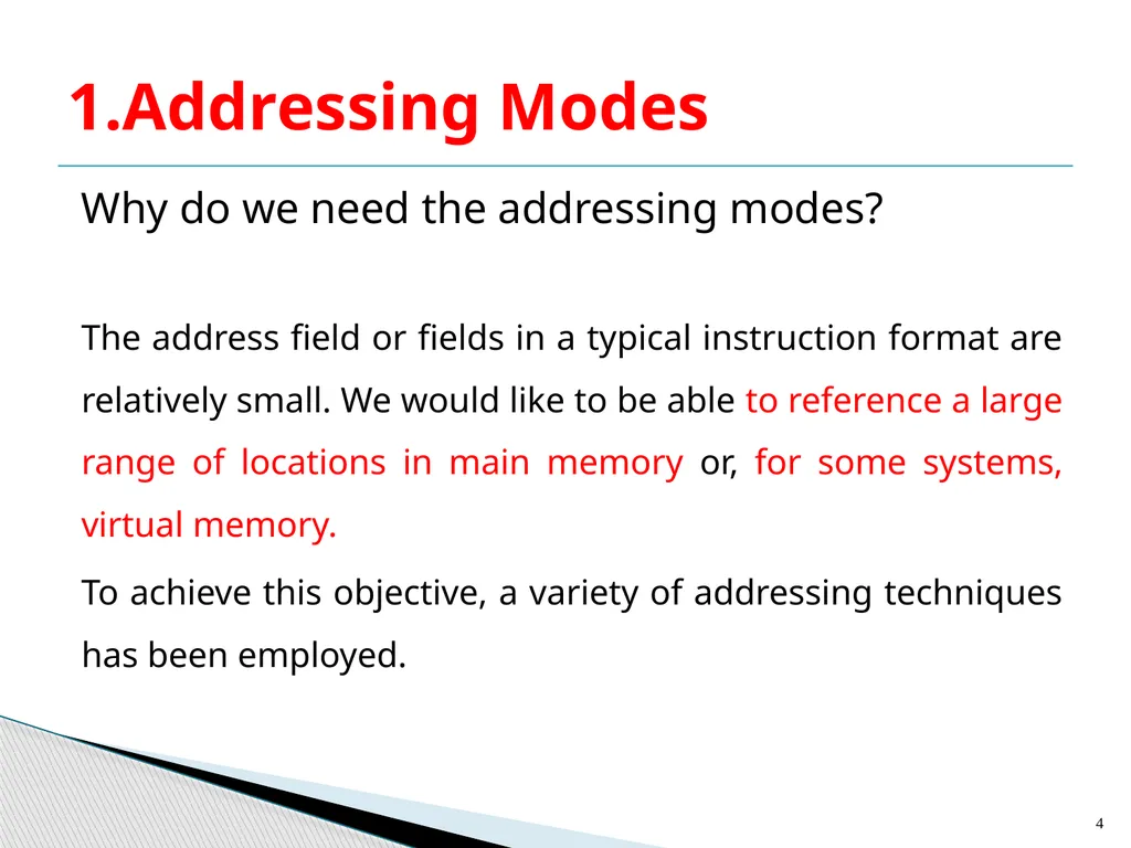
Why do we need the addressing modes?
The address field or fields in a typical instruction format are relatively small. We would like to be able to reference a large range of locations in main memory or, for some systems, virtual memory.
To achieve this objective, a variety of addressing techniques has been employed. 1.Addressing Modes 4<br>
The address field or fields in a typical instruction format are relatively small. We would like to be able to reference a large range of locations in main memory or, for some systems, virtual memory.
To achieve this objective, a variety of addressing techniques has been employed. 1.Addressing Modes 4<br>
05
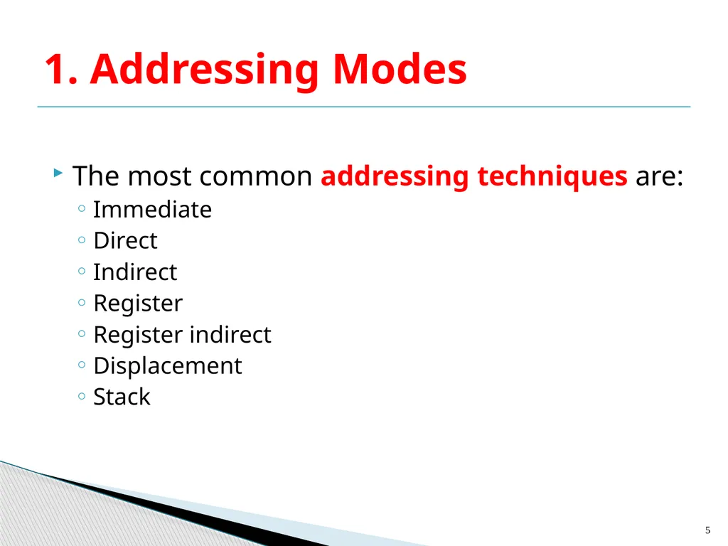
The most common addressing techniques are:
Immediate
Direct
Indirect
Register
Register indirect
Displacement
Stack 1. Addressing Modes 5<br>
Immediate
Direct
Indirect
Register
Register indirect
Displacement
Stack 1. Addressing Modes 5<br>
06
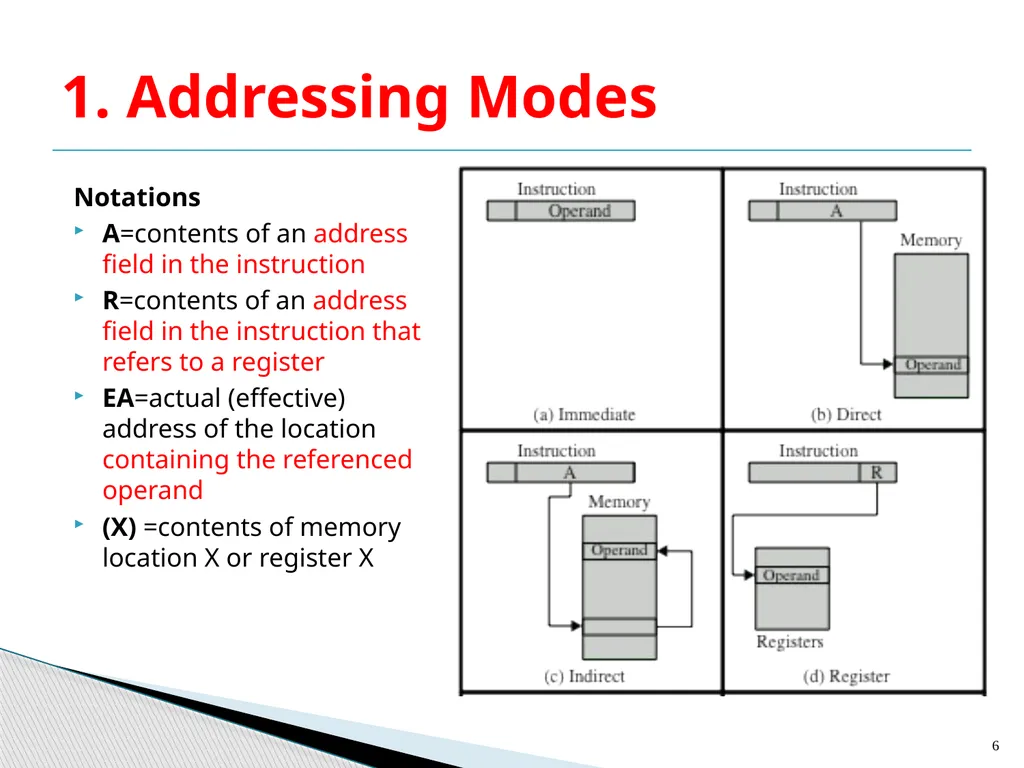
Notations
A=contents of an address field in the instruction
R=contents of an address field in the instruction that refers to a register
EA=actual (effective) address of the location containing the referenced operand
(X) =contents of memory location X or register X 1. Addressing Modes 6<br>
A=contents of an address field in the instruction
R=contents of an address field in the instruction that refers to a register
EA=actual (effective) address of the location containing the referenced operand
(X) =contents of memory location X or register X 1. Addressing Modes 6<br>
07
7<br>
08
Virtually all computer architectures provide more than one of these addressing modes.
One or more bits in the instruction format can be used as a mode field.
The value of the mode field determines which addressing mode is to be used by the processor. 1. Addressing Modes 8<br>
One or more bits in the instruction format can be used as a mode field.
The value of the mode field determines which addressing mode is to be used by the processor. 1. Addressing Modes 8<br>
09
The second comment concerns the interpretation of the effective address (EA).
In a system without virtual memory, the effective address will be either a main memory address or a register.
In a virtual memory system, the effective address is a virtual address or a register. 1. Addressing Modes 9<br>
In a system without virtual memory, the effective address will be either a main memory address or a register.
In a virtual memory system, the effective address is a virtual address or a register. 1. Addressing Modes 9<br>
10
Simplest form of addressing, the operand value is present in the instruction
Operand= A
where A = contents of an address field in the instruction
This mode can be used to define and use constants or set initial values of variables
Typically the number will be stored in twos complement form
The leftmost bit of the operand field is used as a sign bit (a) Immediate Addressing 10<br>
Operand= A
where A = contents of an address field in the instruction
This mode can be used to define and use constants or set initial values of variables
Typically the number will be stored in twos complement form
The leftmost bit of the operand field is used as a sign bit (a) Immediate Addressing 10<br>
11
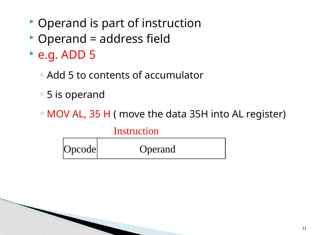
11 Operand is part of instruction
Operand = address field
e.g. ADD 5
Add 5 to contents of accumulator
5 is operand
MOV AL, 35 H ( move the data 35H into AL register)<br>
Operand = address field
e.g. ADD 5
Add 5 to contents of accumulator
5 is operand
MOV AL, 35 H ( move the data 35H into AL register)<br>
12
Advantage
No memory reference other than the instruction fetch is required to obtain the operand, thus saving one memory or cache cycle in the instruction cycle.
Disadvantage
The size of the number is restricted to the size of the address field, which, in most instruction sets, is small compared with the word length. Immediate Addressing 12<br>
No memory reference other than the instruction fetch is required to obtain the operand, thus saving one memory or cache cycle in the instruction cycle.
Disadvantage
The size of the number is restricted to the size of the address field, which, in most instruction sets, is small compared with the word length. Immediate Addressing 12<br>
13
(b) Direct Addressing Simple form of addressing
EA=A
Address field in the instruction contains the EA of the operand and no intermediate memory access is required
It requires only one memory reference and no special calculation.
The length of the address field is usually less than the word length, thus limiting the address range.
This technique was common in earlier generations of computers. 13<br>
EA=A
Address field in the instruction contains the EA of the operand and no intermediate memory access is required
It requires only one memory reference and no special calculation.
The length of the address field is usually less than the word length, thus limiting the address range.
This technique was common in earlier generations of computers. 13<br>
14
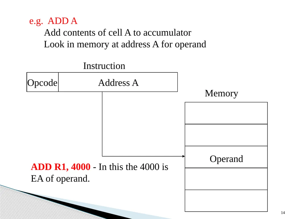
14 e.g. ADD A
Add contents of cell A to accumulator
Look in memory at address A for operand ADD R1, 4000 - In this the 4000 is EA of operand.<br>
Add contents of cell A to accumulator
Look in memory at address A for operand ADD R1, 4000 - In this the 4000 is EA of operand.<br>
15
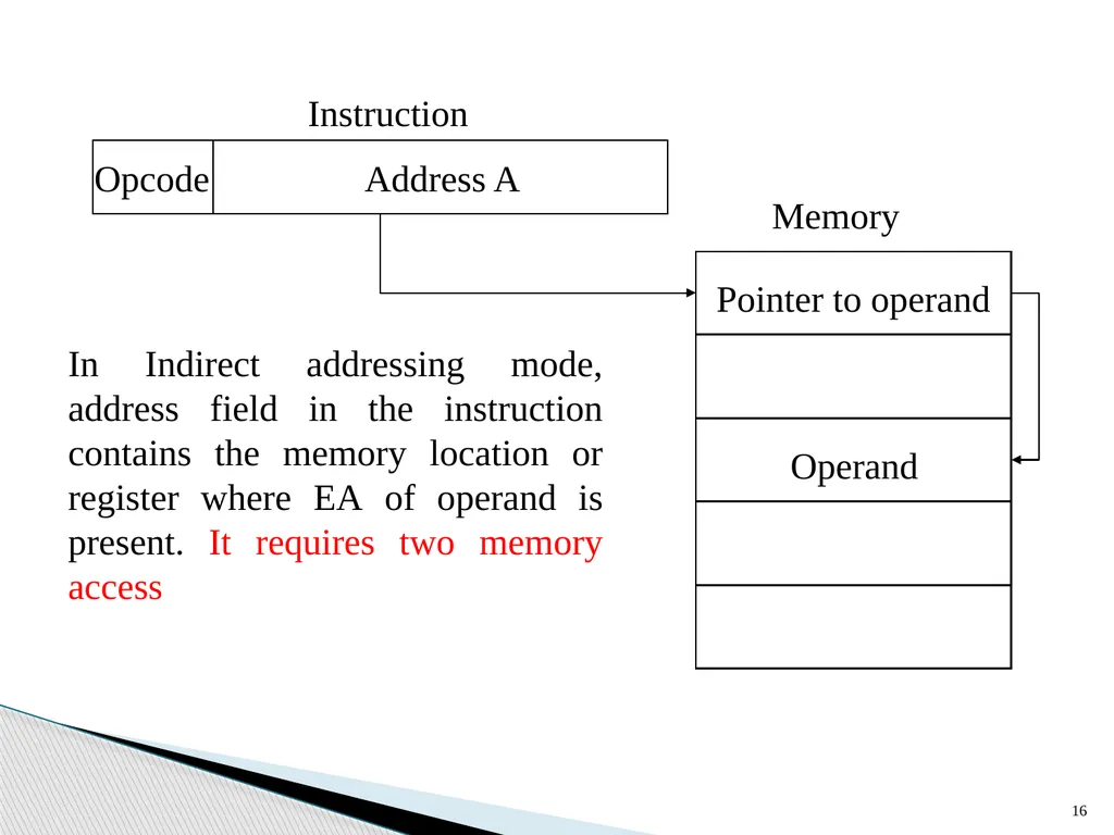
Indirect addressing is a scheme in which the address specifies which memory word or register contains not the operand but the address of the operand.
EA = (A)
Instruction execution requires two memory references to fetch the operand
One to get its address and a second to get its value
e.g. ADD (A)
Add contents of cell pointed to by contents of A to accumulator (c) Indirect Addressing 15<br>
EA = (A)
Instruction execution requires two memory references to fetch the operand
One to get its address and a second to get its value
e.g. ADD (A)
Add contents of cell pointed to by contents of A to accumulator (c) Indirect Addressing 15<br>
16
16 In Indirect addressing mode, address field in the instruction contains the memory location or register where EA of operand is present. It requires two memory access<br>
17
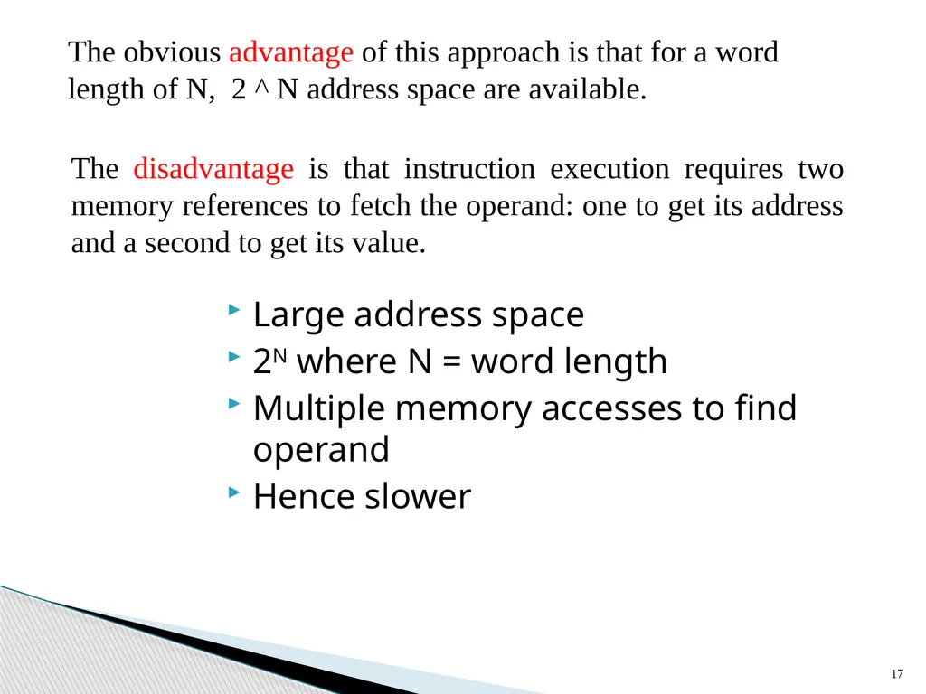
17 The obvious advantage of this approach is that for a word length of N, 2 ^ N address space are available. The disadvantage is that instruction execution requires two memory references to fetch the operand: one to get its address and a second to get its value. Large address space
2N where N = word length
Multiple memory accesses to find operand
Hence slower<br>
2N where N = word length
Multiple memory accesses to find operand
Hence slower<br>
18
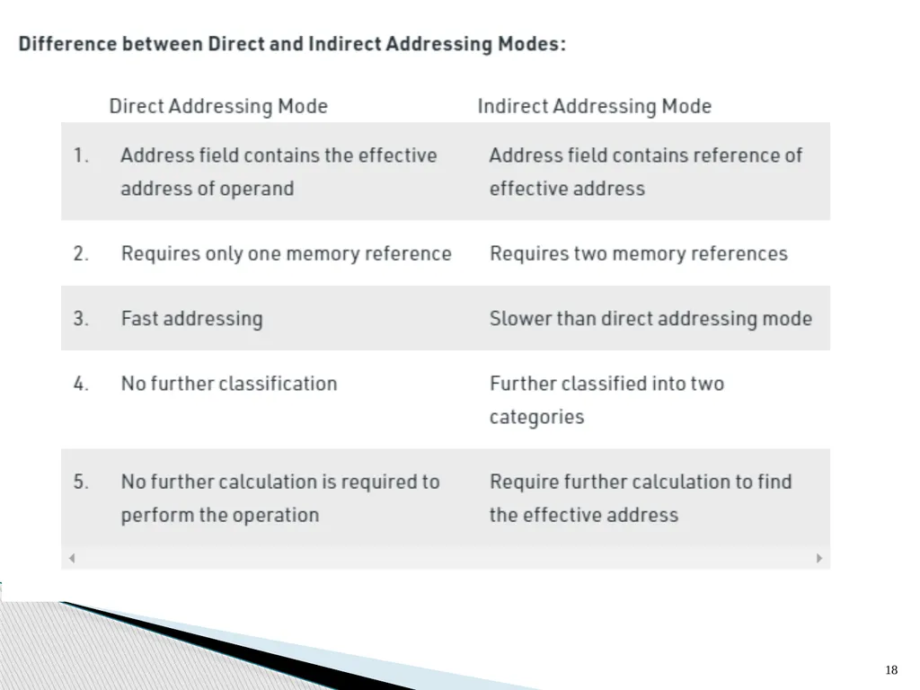
18<br>
19
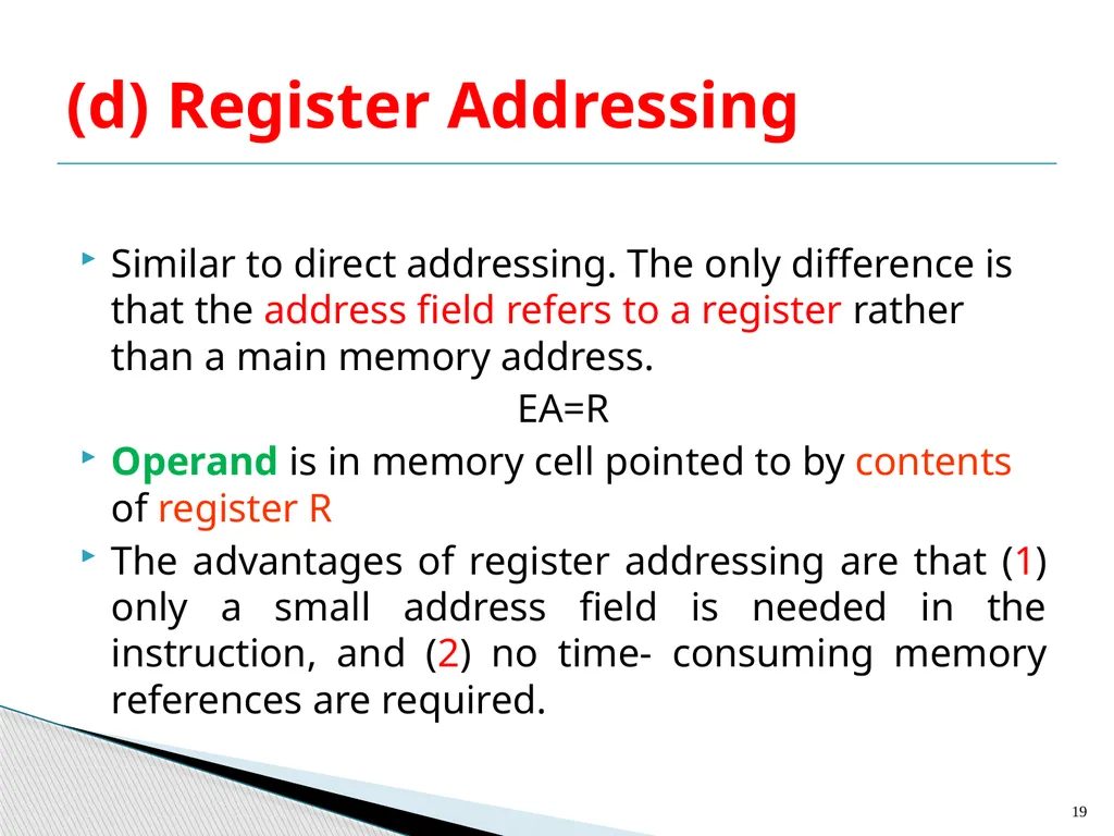
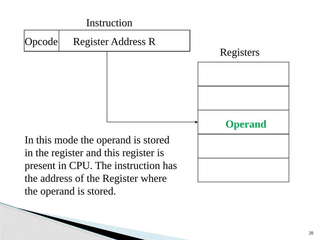
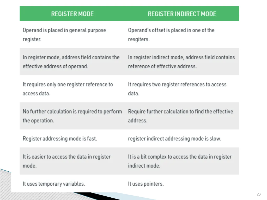
Similar to direct addressing. The only difference is that the address field refers to a register rather than a main memory address.
EA=R
Operand is in memory cell pointed to by contents of register R
The advantages of register addressing are that (1) only a small address field is needed in the instruction, and (2) no time- consuming memory references are required. (d) Register Addressing 19<br>
EA=R
Operand is in memory cell pointed to by contents of register R
The advantages of register addressing are that (1) only a small address field is needed in the instruction, and (2) no time- consuming memory references are required. (d) Register Addressing 19<br>
20
20 In this mode the operand is stored in the register and this register is present in CPU. The instruction has the address of the Register where the operand is stored.<br>
21
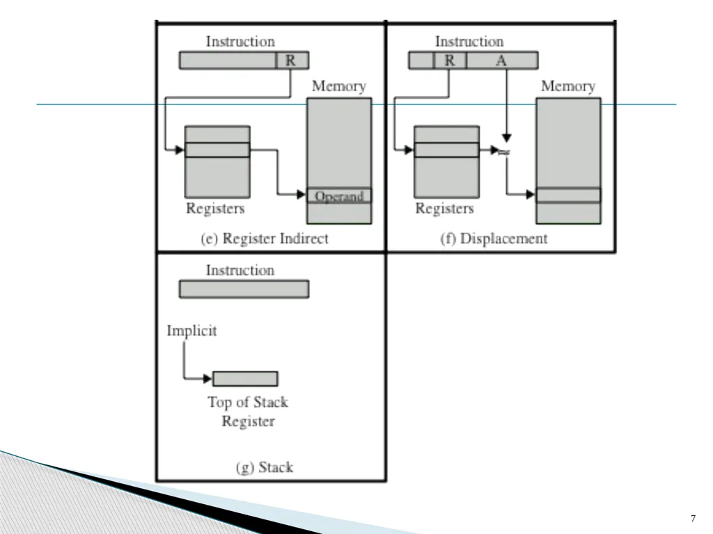
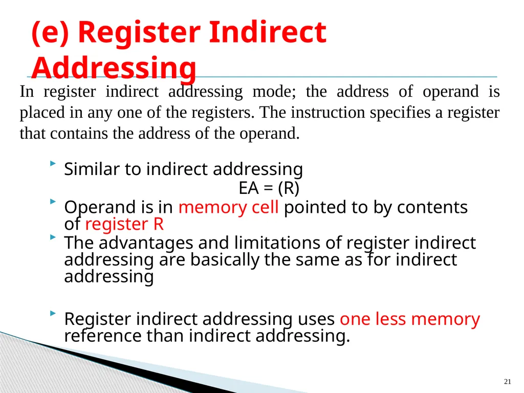
Similar to indirect addressing
EA = (R)
Operand is in memory cell pointed to by contents of register R
The advantages and limitations of register indirect addressing are basically the same as for indirect addressing
Register indirect addressing uses one less memory reference than indirect addressing. (e) Register Indirect Addressing 21 In register indirect addressing mode; the address of operand is placed in any one of the registers. The instruction specifies a register that contains the address of the operand.<br>
EA = (R)
Operand is in memory cell pointed to by contents of register R
The advantages and limitations of register indirect addressing are basically the same as for indirect addressing
Register indirect addressing uses one less memory reference than indirect addressing. (e) Register Indirect Addressing 21 In register indirect addressing mode; the address of operand is placed in any one of the registers. The instruction specifies a register that contains the address of the operand.<br>
22
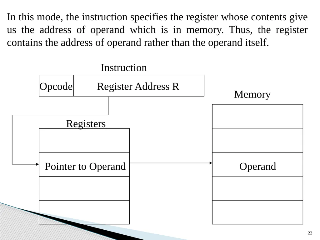
22 In this mode, the instruction specifies the register whose contents give us the address of operand which is in memory. Thus, the register contains the address of operand rather than the operand itself.<br>
23
23<br>
24
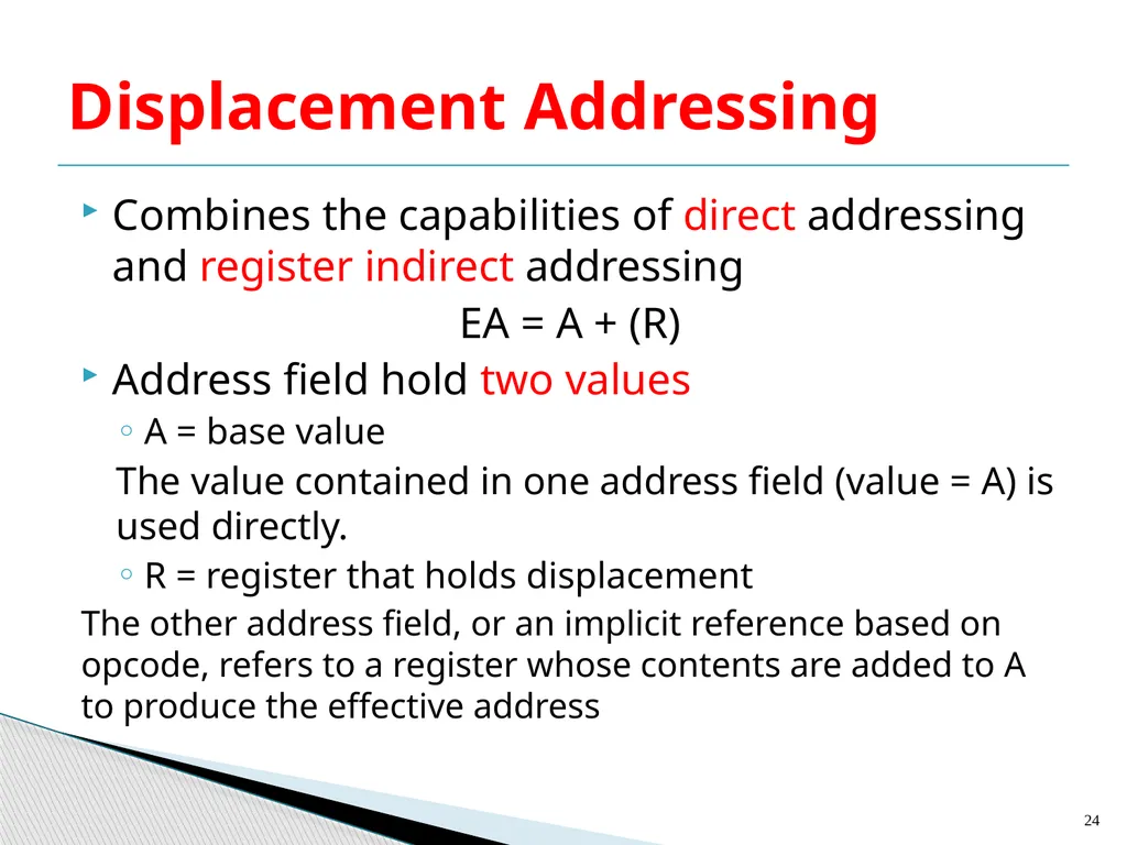
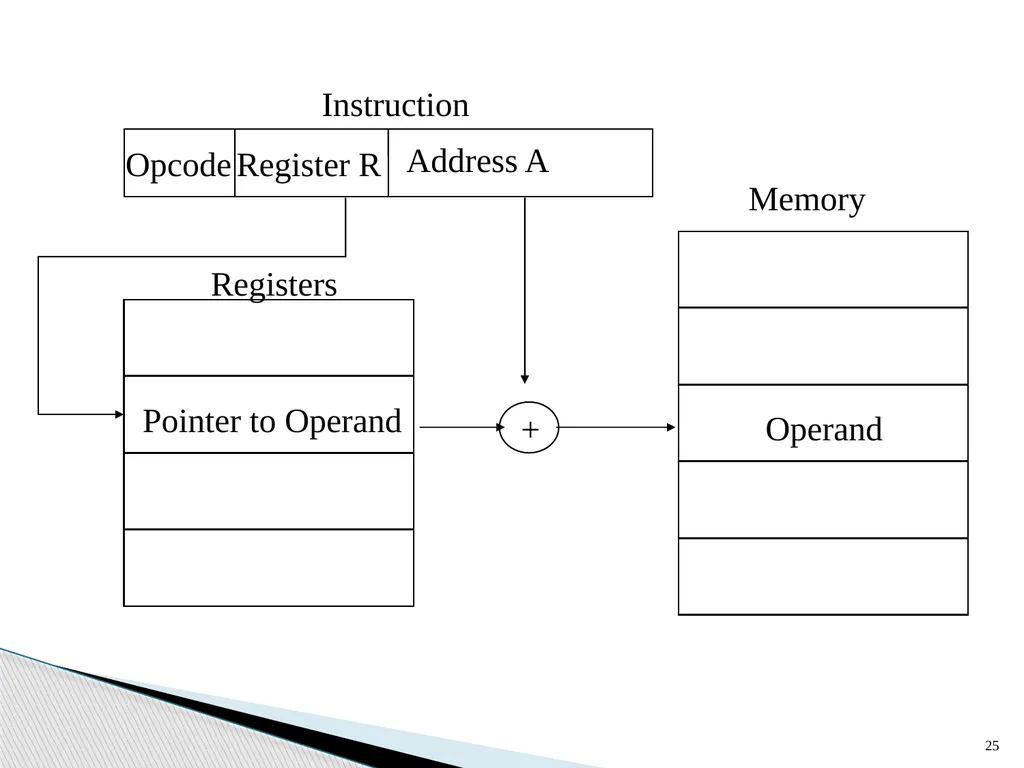
Combines the capabilities of direct addressing and register indirect addressing
EA = A + (R)
Address field hold two values
A = base value
The value contained in one address field (value = A) is used directly.
R = register that holds displacement
The other address field, or an implicit reference based on opcode, refers to a register whose contents are added to A to produce the effective address Displacement Addressing 24<br>
EA = A + (R)
Address field hold two values
A = base value
The value contained in one address field (value = A) is used directly.
R = register that holds displacement
The other address field, or an implicit reference based on opcode, refers to a register whose contents are added to A to produce the effective address Displacement Addressing 24<br>
25
25<br>
26
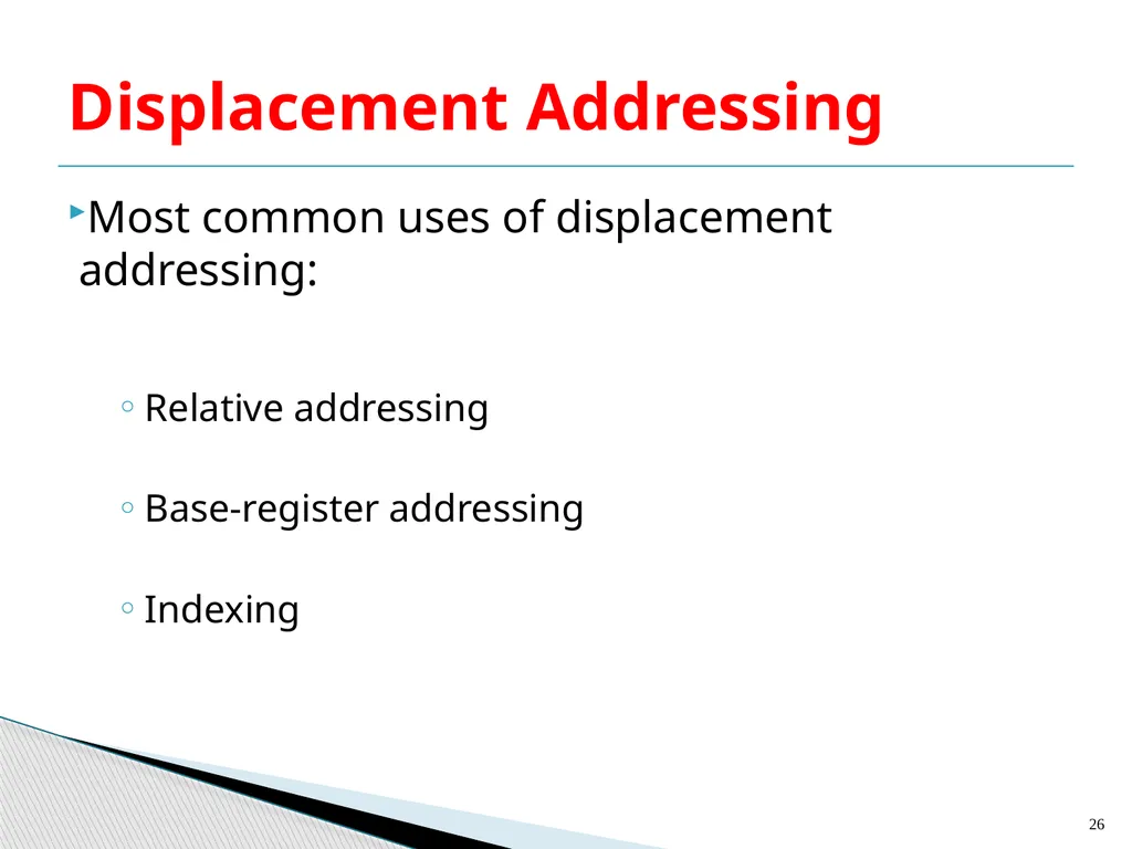
Most common uses of displacement addressing:
Relative addressing
Base-register addressing
Indexing Displacement Addressing 26<br>
Relative addressing
Base-register addressing
Indexing Displacement Addressing 26<br>
27
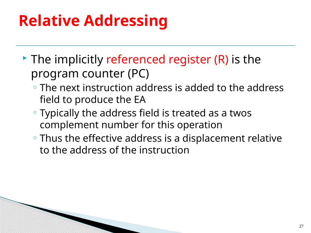
The implicitly referenced register (R) is the program counter (PC)
The next instruction address is added to the address field to produce the EA
Typically the address field is treated as a twos complement number for this operation
Thus the effective address is a displacement relative to the address of the instruction Relative Addressing 27<br>
The next instruction address is added to the address field to produce the EA
Typically the address field is treated as a twos complement number for this operation
Thus the effective address is a displacement relative to the address of the instruction Relative Addressing 27<br>
28
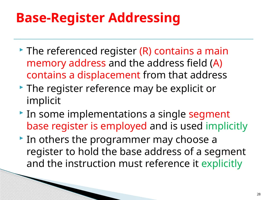
The referenced register (R) contains a main memory address and the address field (A) contains a displacement from that address
The register reference may be explicit or implicit
In some implementations a single segment base register is employed and is used implicitly
In others the programmer may choose a register to hold the base address of a segment and the instruction must reference it explicitly Base-Register Addressing 28<br>
The register reference may be explicit or implicit
In some implementations a single segment base register is employed and is used implicitly
In others the programmer may choose a register to hold the base address of a segment and the instruction must reference it explicitly Base-Register Addressing 28<br>
29
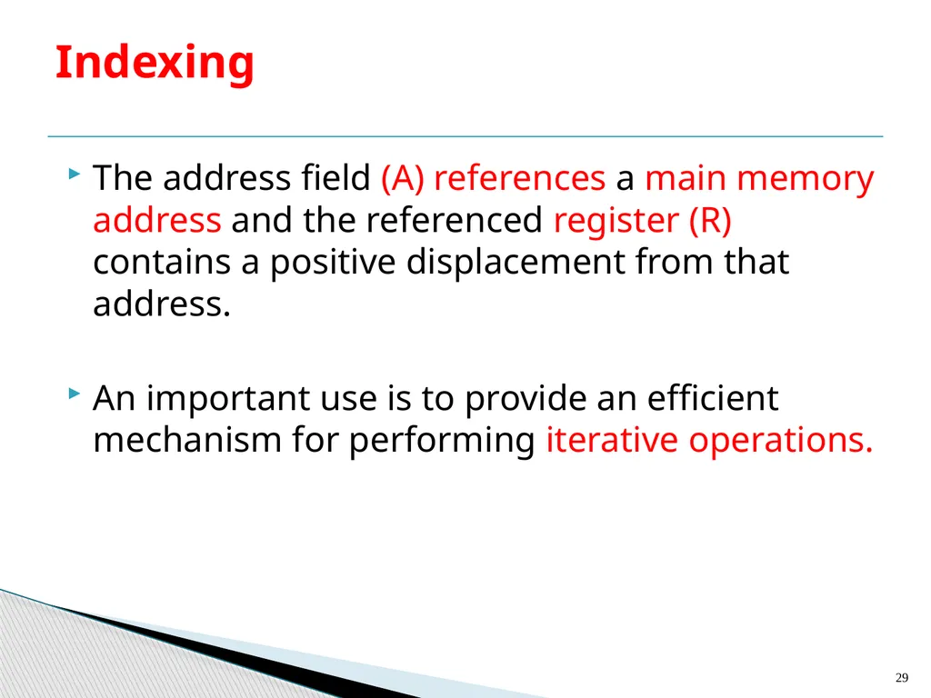
The address field (A) references a main memory address and the referenced register (R) contains a positive displacement from that address.
An important use is to provide an efficient mechanism for performing iterative operations. Indexing 29<br>
An important use is to provide an efficient mechanism for performing iterative operations. Indexing 29<br>
30
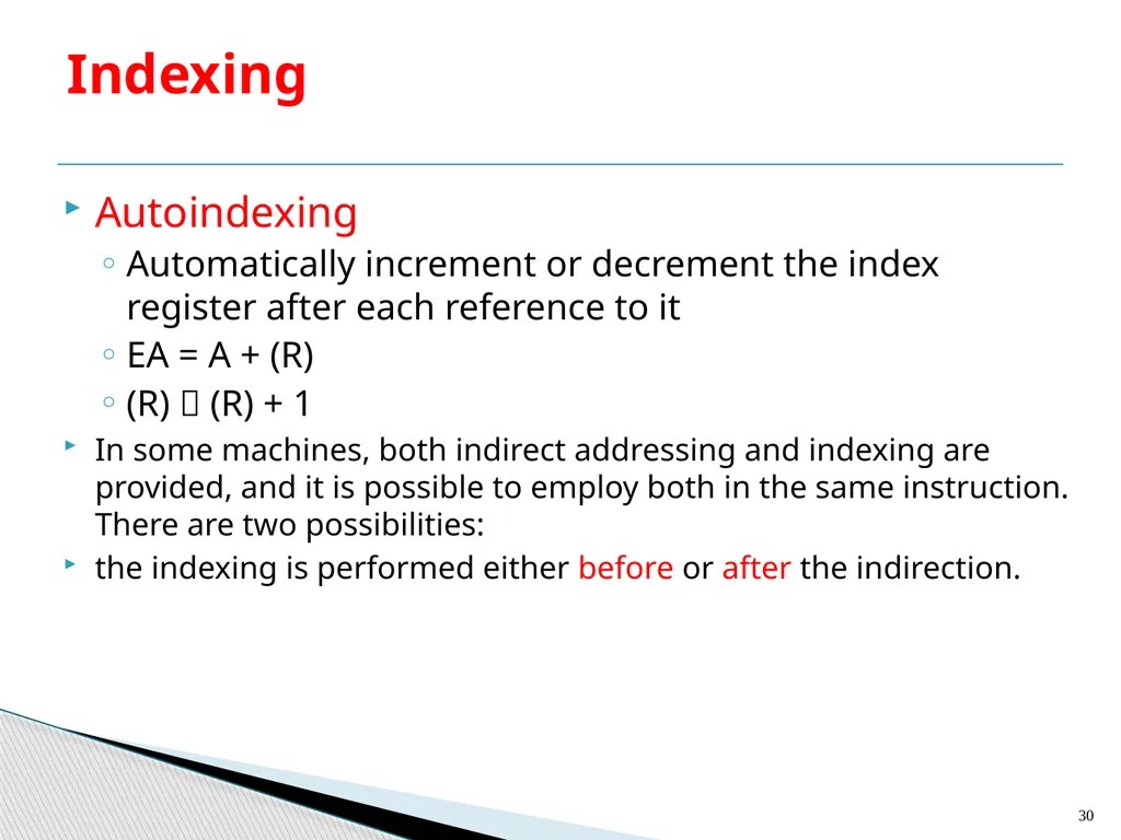
Autoindexing
Automatically increment or decrement the index register after each reference to it
EA = A + (R)
(R) (R) + 1
In some machines, both indirect addressing and indexing are provided, and it is possible to employ both in the same instruction. There are two possibilities:
the indexing is performed either before or after the indirection. Indexing 30<br>
Automatically increment or decrement the index register after each reference to it
EA = A + (R)
(R) (R) + 1
In some machines, both indirect addressing and indexing are provided, and it is possible to employ both in the same instruction. There are two possibilities:
the indexing is performed either before or after the indirection. Indexing 30<br>
31
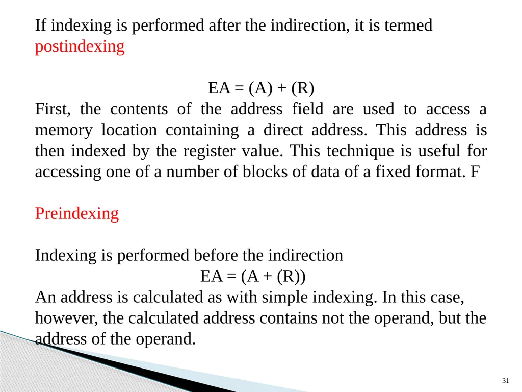
31 If indexing is performed after the indirection, it is termed postindexing
EA = (A) + (R)
First, the contents of the address field are used to access a memory location containing a direct address. This address is then indexed by the register value. This technique is useful for accessing one of a number of blocks of data of a fixed format. F
Preindexing
Indexing is performed before the indirection
EA = (A + (R))
An address is calculated as with simple indexing. In this case, however, the calculated address contains not the operand, but the address of the operand.<br>
EA = (A) + (R)
First, the contents of the address field are used to access a memory location containing a direct address. This address is then indexed by the register value. This technique is useful for accessing one of a number of blocks of data of a fixed format. F
Preindexing
Indexing is performed before the indirection
EA = (A + (R))
An address is calculated as with simple indexing. In this case, however, the calculated address contains not the operand, but the address of the operand.<br>
32
Remember that a stack is a linear array of locations works as a last-in-first-out queue.
Items are appended to the top of the stack so that the block is partially filled at any time.
Associated with the stack is a pointer whose value is the address of the top of the stack
The stack pointer is maintained in a register
Thus references to stack locations in memory are in fact register indirect addresses
The machine instructions need not include a memory reference but implicitly operate on the top of the stack. Stack Addressing 32<br>
Items are appended to the top of the stack so that the block is partially filled at any time.
Associated with the stack is a pointer whose value is the address of the top of the stack
The stack pointer is maintained in a register
Thus references to stack locations in memory are in fact register indirect addresses
The machine instructions need not include a memory reference but implicitly operate on the top of the stack. Stack Addressing 32<br>
33
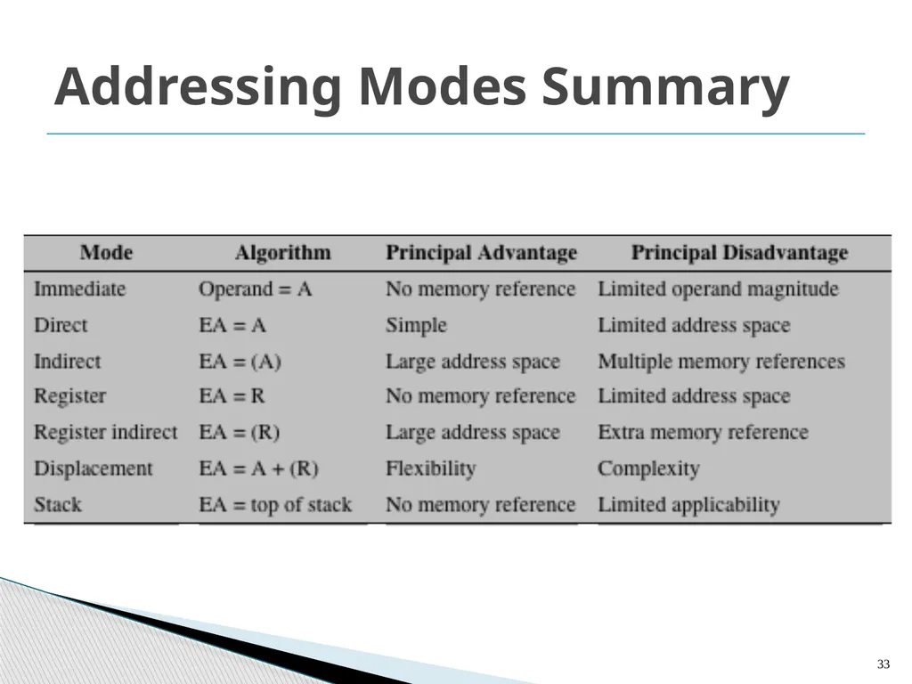
Addressing Modes Summary 33<br>
34
34 An instruction format defines the layout of the bits of an instruction, in terms of its constituent fields. An instruction format must include an opcode and, implicitly or explicitly, zero or more operands. Each explicit operand is referenced using one of the addressing modes. The format must, implicitly or explicitly, indicate the addressing mode for each operand. For most instruction sets, more than one instruction format is used. 2. Instruction Formats<br>
35
The most basic design issue is the instruction length.
The decision affects, and is affected by:
Memory size
Memory organization
Bus structure
Processor complexity
Processor speed
The most obvious trade-off here is between the desire for a powerful instruction repertoire and a need to save space. Instruction Length 35<br>
The decision affects, and is affected by:
Memory size
Memory organization
Bus structure
Processor complexity
Processor speed
The most obvious trade-off here is between the desire for a powerful instruction repertoire and a need to save space. Instruction Length 35<br>
36
36 More opcodes and more operands make life easier for the programmer. Why? Because shorter programs can be written to accomplish given tasks.
Similarly, more addressing modes give the programmer greater flexibility in implementing certain functions, such as table manipulations and multiple- way branching. And, of course, with the increase in main memory size and the increasing use of virtual memory, programmers want to be able to address larger memory ranges. All of these things (opcodes, operands, addressing modes, address range) require bits and push in the direction of longer instruction
lengths. But longer instruction length may be wasteful. A 64-bit instruction occupies twice the space of a 32-bit instruction but is probably less than twice as useful.<br>
Similarly, more addressing modes give the programmer greater flexibility in implementing certain functions, such as table manipulations and multiple- way branching. And, of course, with the increase in main memory size and the increasing use of virtual memory, programmers want to be able to address larger memory ranges. All of these things (opcodes, operands, addressing modes, address range) require bits and push in the direction of longer instruction
lengths. But longer instruction length may be wasteful. A 64-bit instruction occupies twice the space of a 32-bit instruction but is probably less than twice as useful.<br>
37
37 Beyond this basic trade-off, there are other considerations. Either the instruction length should be equal to the memory-transfer length (in a bus system, data bus length) or one should be a multiple of the other. A related consideration is the memory transfer rate. This rate has not kept up with increases in processor speed. Accordingly, memory can become a bottleneck if the processor can execute
instructions faster than it can fetch them. One solution to this problem is to use (i) cache memory; (ii) shorter instructions. Thus, 16-bit instructions can be fetched at twice the rate of 32-bit instructions but probably can be executed less than twice as rapidly.<br>
instructions faster than it can fetch them. One solution to this problem is to use (i) cache memory; (ii) shorter instructions. Thus, 16-bit instructions can be fetched at twice the rate of 32-bit instructions but probably can be executed less than twice as rapidly.<br>
38
38 Allocation of Bits An equally difficult issue is how to allocate the bits in that format.
For a given instruction length, there is clearly a trade-off between the number of opcodes and the power of the addressing capability. More opcodes obviously mean more bits in the opcode field. For an instruction format of a given length, this reduces the number of bits available for addressing.!!!!!!
There is one interesting refinement to this trade-off, and that is the use of variable-length opcodes.<br>
For a given instruction length, there is clearly a trade-off between the number of opcodes and the power of the addressing capability. More opcodes obviously mean more bits in the opcode field. For an instruction format of a given length, this reduces the number of bits available for addressing.!!!!!!
There is one interesting refinement to this trade-off, and that is the use of variable-length opcodes.<br>
39
39 In this approach, there is a minimum opcode length but, for some opcodes, additional operations may be specified by using additional bits in the instruction.
For a fixed length instruction, this leaves fewer bits for addressing. Thus, this feature is used for those instructions that require fewer operands and/or less powerful addressing. The following interrelated factors go into determining the use of the addressing bits Number of addressing modes
Number of operands
Register versus memory
Number of register sets
Address range<br>
For a fixed length instruction, this leaves fewer bits for addressing. Thus, this feature is used for those instructions that require fewer operands and/or less powerful addressing. The following interrelated factors go into determining the use of the addressing bits Number of addressing modes
Number of operands
Register versus memory
Number of register sets
Address range<br>
40
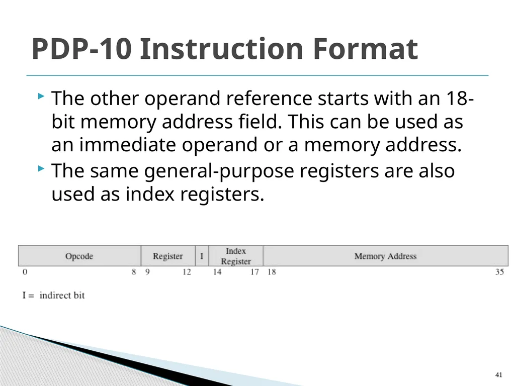
The PDP-10 has a 36-bit word length and a 36-bit instruction length.
The opcode occupies 9 bits, allowing up to 512 operations. In fact, a total of 365 different instructions are defined.
Most instructions have two addresses, one of which is one of 16 general-purpose registers. Thus, this operand reference occupies 4 bits. PDP-10 Instruction Format 40<br>
The opcode occupies 9 bits, allowing up to 512 operations. In fact, a total of 365 different instructions are defined.
Most instructions have two addresses, one of which is one of 16 general-purpose registers. Thus, this operand reference occupies 4 bits. PDP-10 Instruction Format 40<br>
41
The other operand reference starts with an 18-bit memory address field. This can be used as an immediate operand or a memory address.
The same general-purpose registers are also used as index registers. PDP-10 Instruction Format 41<br>
The same general-purpose registers are also used as index registers. PDP-10 Instruction Format 41<br>
42
Variations can be provided efficiently and compactly
Increases the complexity of the processor
Does not remove the desirability of making all of the instruction lengths integrally related to word length
Because the processor does not know the length of the next instruction to be fetched a typical strategy is to fetch a number of bytes or words equal to at least the longest possible instruction
Sometimes multiple instructions are fetched Variable-Length Instructions 42<br>
Increases the complexity of the processor
Does not remove the desirability of making all of the instruction lengths integrally related to word length
Because the processor does not know the length of the next instruction to be fetched a typical strategy is to fetch a number of bytes or words equal to at least the longest possible instruction
Sometimes multiple instructions are fetched Variable-Length Instructions 42<br>
43
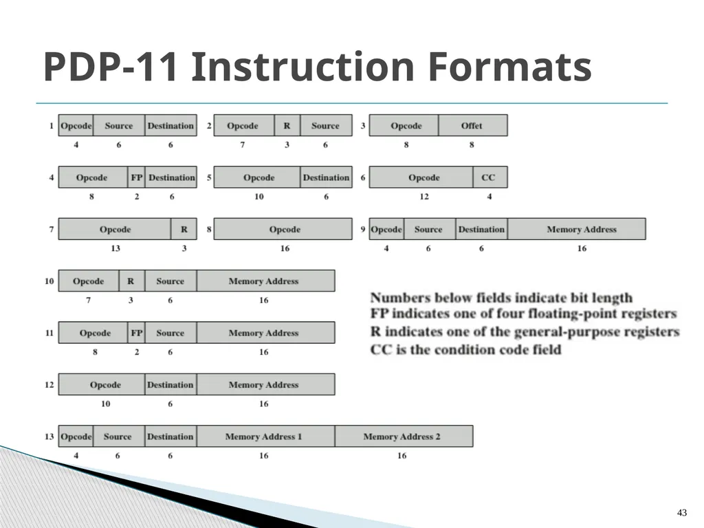
PDP-11 Instruction Formats 43<br>
44
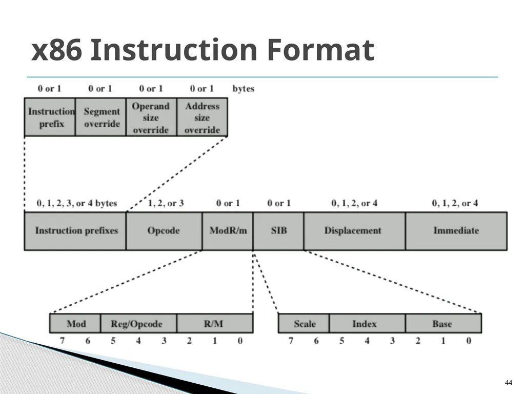
x86 Instruction Format 44<br>
45
x86 Instruction Format Instructions are made up of:
from zero to four optional instruction prefixes
a 1-, 2- or 3-byte opcode
an optional address specifier (which consists of the ModR/m byte and the Scale Index byte)
an optional displacement
an optional immediate field 45<br>
from zero to four optional instruction prefixes
a 1-, 2- or 3-byte opcode
an optional address specifier (which consists of the ModR/m byte and the Scale Index byte)
an optional displacement
an optional immediate field 45<br>
46
x86 Instruction Format The instruction prefix, if present, consists of the LOCK prefix or one of the repeat prefixes.
The LOCK prefix is used to ensure exclusive use of shared memory in multiprocessor environments.
The repeat prefixes specify repeated operation of a string, which enables the x86 to process strings much faster than with a regular software loop. 46<br>
The LOCK prefix is used to ensure exclusive use of shared memory in multiprocessor environments.
The repeat prefixes specify repeated operation of a string, which enables the x86 to process strings much faster than with a regular software loop. 46<br>
47
x86 Instruction Format Segment override explicitly specifies which segment register an instruction should use, overriding the default segment-register selection generated by the x86 for that instruction.
An instruction has a default operand size of 16 or 32 bits, and the operand prefix switches between 32-bit and 16-bit operands. 47<br>
An instruction has a default operand size of 16 or 32 bits, and the operand prefix switches between 32-bit and 16-bit operands. 47<br>
48
x86 Instruction Format The processor can address memory using either 16- or 32-bit address size.
The opcode field is 1, 2, or 3 bytes in length.
The ModR/m byte specifies whether an operand is in a register or in memory; if it is in memory, then fields within the byte specify the addressing mode to be used. 48<br>
The opcode field is 1, 2, or 3 bytes in length.
The ModR/m byte specifies whether an operand is in a register or in memory; if it is in memory, then fields within the byte specify the addressing mode to be used. 48<br>
49
x86 Instruction Format Certain encoding of the ModR/m byte specifies the inclusion of the SIB byte to specify fully the addressing mode.
When the addressing-mode specifier indicates that a displacement is used, an 8-, 16-, or 32-bit signed integer displacement field is added.
Immediate field provides the value of an 8-, 16-, or 32-bit operand. 49<br>
When the addressing-mode specifier indicates that a displacement is used, an 8-, 16-, or 32-bit signed integer displacement field is added.
Immediate field provides the value of an 8-, 16-, or 32-bit operand. 49<br>
50
Assembly Language A processor can understand and execute machine instructions. Such instructions are simply binary numbers stored in the computer.
If a programmer wishes to program directly in machine language, then it would be necessary to enter the program as binary data.
Consider the simple BASIC statement
N=I +J +K
and suppose we wish to program this statement in machine language and to initialize I, J, and K to 2, 3, and 4, respectively. 50<br>
If a programmer wishes to program directly in machine language, then it would be necessary to enter the program as binary data.
Consider the simple BASIC statement
N=I +J +K
and suppose we wish to program this statement in machine language and to initialize I, J, and K to 2, 3, and 4, respectively. 50<br>
51
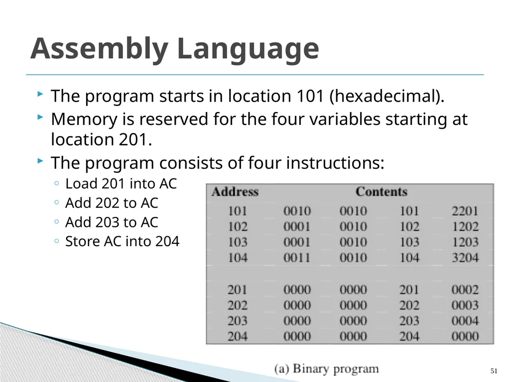
Assembly Language The program starts in location 101 (hexadecimal).
Memory is reserved for the four variables starting at location 201.
The program consists of four instructions:
Load 201 into AC
Add 202 to AC
Add 203 to AC
Store AC into 204 51<br>
Memory is reserved for the four variables starting at location 201.
The program consists of four instructions:
Load 201 into AC
Add 202 to AC
Add 203 to AC
Store AC into 204 51<br>
52
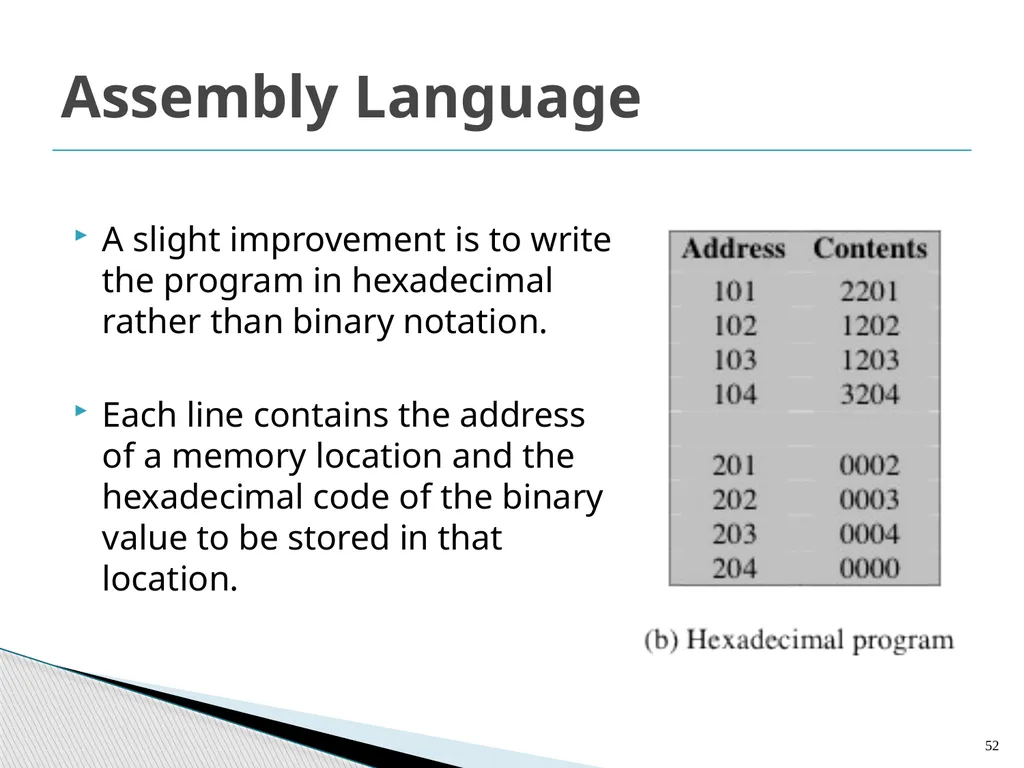
Assembly Language A slight improvement is to write the program in hexadecimal rather than binary notation.
Each line contains the address of a memory location and the hexadecimal code of the binary value to be stored in that location. 52<br>
Each line contains the address of a memory location and the hexadecimal code of the binary value to be stored in that location. 52<br>
53
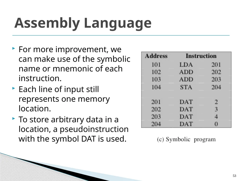
Assembly Language For more improvement, we can make use of the symbolic name or mnemonic of each instruction.
Each line of input still represents one memory location.
To store arbitrary data in a location, a pseudoinstruction with the symbol DAT is used. 53<br>
Each line of input still represents one memory location.
To store arbitrary data in a location, a pseudoinstruction with the symbol DAT is used. 53<br>
54
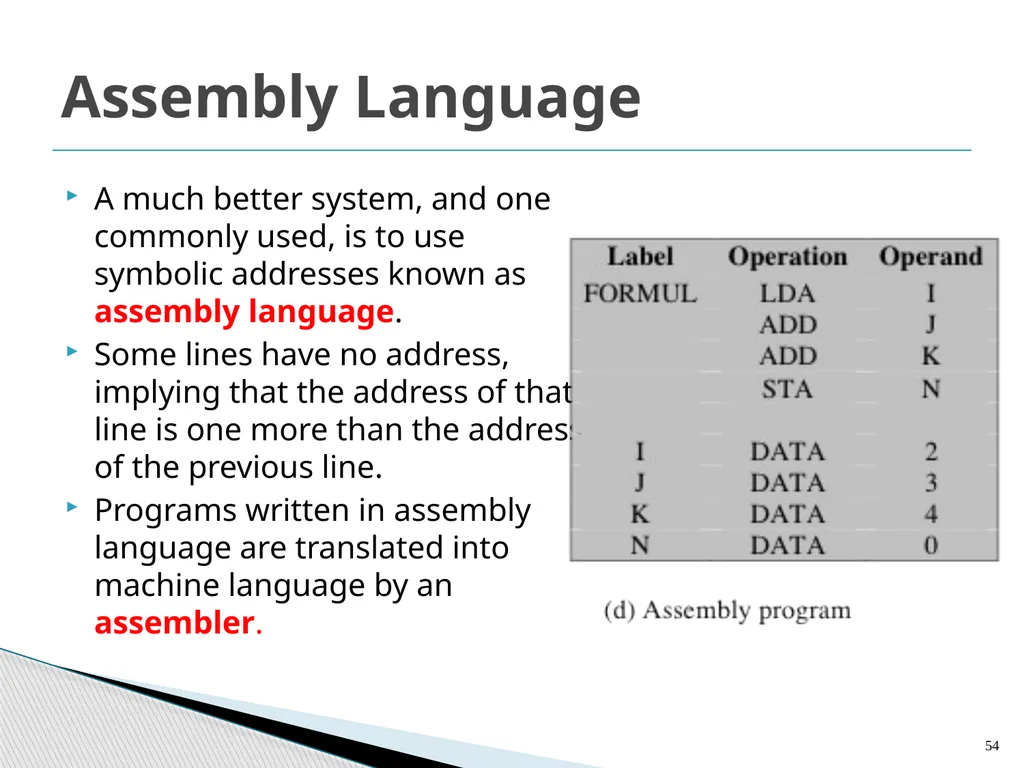
Assembly Language A much better system, and one commonly used, is to use symbolic addresses known as assembly language.
Some lines have no address, implying that the address of that line is one more than the address of the previous line.
Programs written in assembly language are translated into machine language by an assembler. 54<br>
Some lines have no address, implying that the address of that line is one more than the address of the previous line.
Programs written in assembly language are translated into machine language by an assembler. 54<br>
55
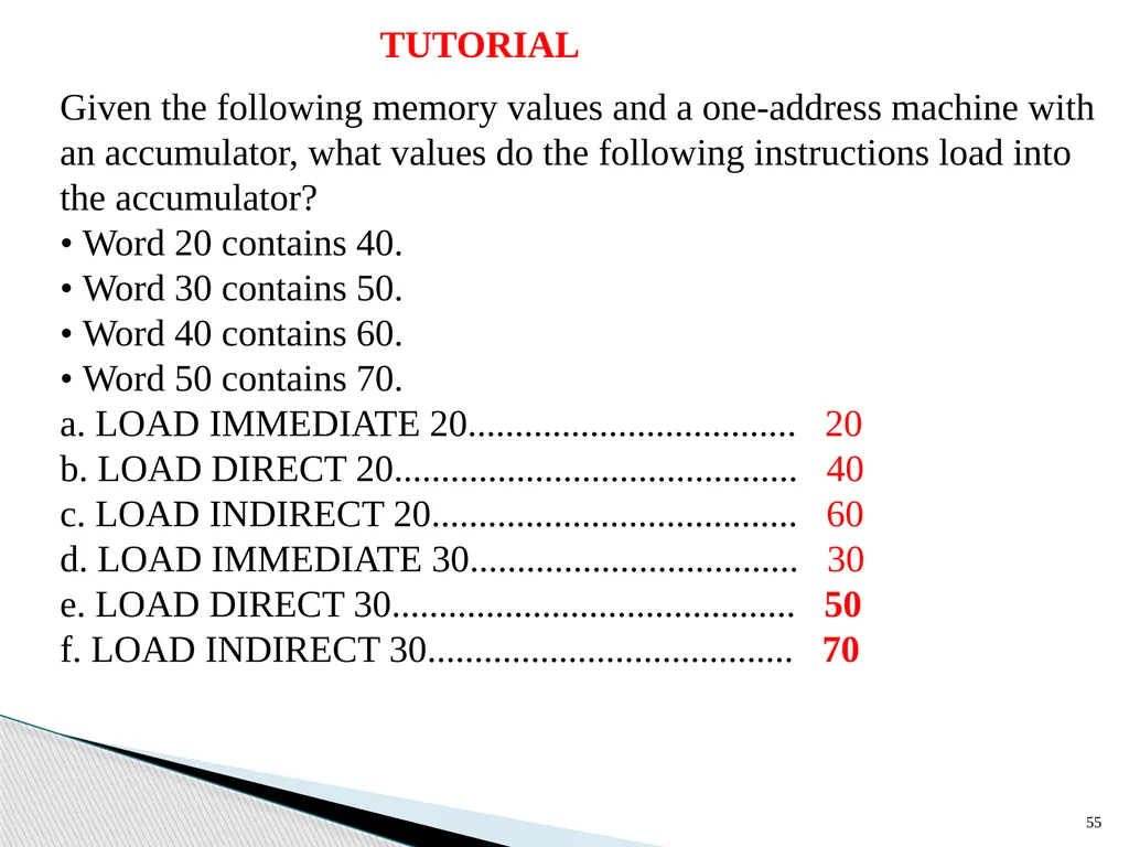
55 Given the following memory values and a one-address machine with an accumulator, what values do the following instructions load into the accumulator?
• Word 20 contains 40.
• Word 30 contains 50.
• Word 40 contains 60.
• Word 50 contains 70.
a. LOAD IMMEDIATE 20................................... 20
b. LOAD DIRECT 20........................................... 40
c. LOAD INDIRECT 20....................................... 60
d. LOAD IMMEDIATE 30................................... 30
e. LOAD DIRECT 30........................................... 50
f. LOAD INDIRECT 30....................................... 70 TUTORIAL<br>
• Word 20 contains 40.
• Word 30 contains 50.
• Word 40 contains 60.
• Word 50 contains 70.
a. LOAD IMMEDIATE 20................................... 20
b. LOAD DIRECT 20........................................... 40
c. LOAD INDIRECT 20....................................... 60
d. LOAD IMMEDIATE 30................................... 30
e. LOAD DIRECT 30........................................... 50
f. LOAD INDIRECT 30....................................... 70 TUTORIAL<br>
56
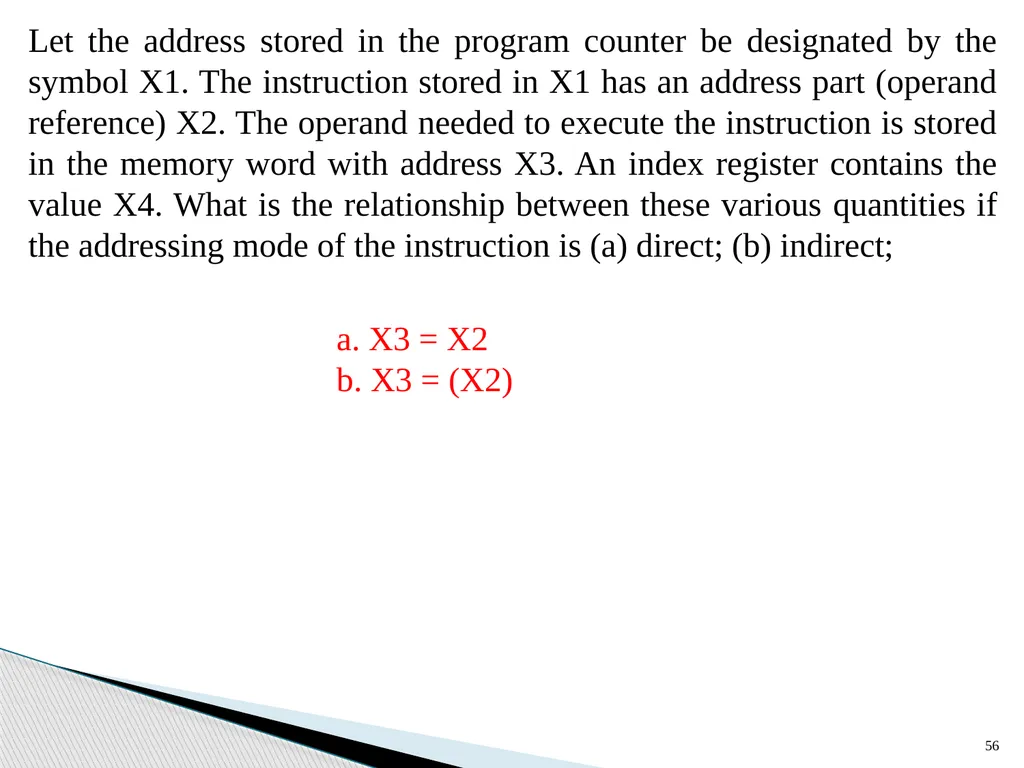
56 Let the address stored in the program counter be designated by the symbol X1. The instruction stored in X1 has an address part (operand reference) X2. The operand needed to execute the instruction is stored in the memory word with address X3. An index register contains the value X4. What is the relationship between these various quantities if the addressing mode of the instruction is (a) direct; (b) indirect; a. X3 = X2
b. X3 = (X2)<br>
b. X3 = (X2)<br>
57
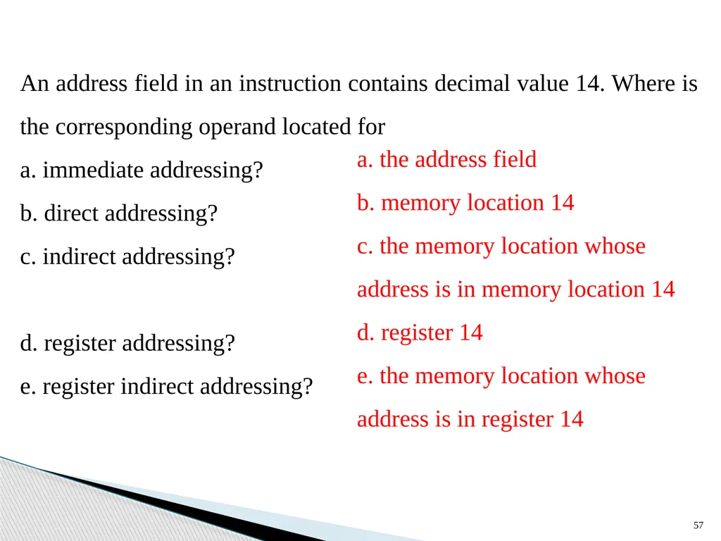
57<br>
58
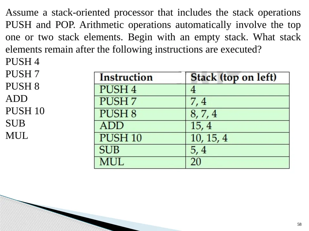
58 Assume a stack-oriented processor that includes the stack operations PUSH and POP. Arithmetic operations automatically involve the top one or two stack elements. Begin with an empty stack. What stack elements remain after the following instructions are executed?
PUSH 4
PUSH 7
PUSH 8
ADD
PUSH 10
SUB
MUL<br>
PUSH 4
PUSH 7
PUSH 8
ADD
PUSH 10
SUB
MUL<br>