
Chapter 11: Fireground Operations Knowledge
KL
Published · 78 slides · 0 views
1 / 1

Description
Chapter 11: Fireground Operations Knowledge Objectives Describe securing a water source after arriving on scene. Describe the driveroperators responsibility with proper hose layouts. Describe cab procedures when positioning the fire
Related Topics
Download this presentation From Below
"Chapter 11: Fireground Operations Knowledge" is the property of its rightful owner. Permission is granted to download and print the materials on this website for personal, non-commercial use only, and to display it on your personal computer provided you do not modify the materials and that you retain all copyright notices contained in the materials. By downloading content from our website, you accept the terms of this agreement.
Share
Embed code
Presentation Transcript
01
Chapter 11: Fireground Operations<br>
02
Knowledge Objectives Describe securing a water source after arriving on scene.
Describe the driver/operator’s responsibility with proper hose layouts.
Describe cab procedures when positioning the fire apparatus at the fireground.
Describe the driver/operator’s responsibilities prior to exiting the cab of the fire apparatus.
Describe the driver/operator’s responsibilities after exiting the fire apparatus.<br>
Describe the driver/operator’s responsibility with proper hose layouts.
Describe cab procedures when positioning the fire apparatus at the fireground.
Describe the driver/operator’s responsibilities prior to exiting the cab of the fire apparatus.
Describe the driver/operator’s responsibilities after exiting the fire apparatus.<br>
03
Knowledge Objectives Describe the driver/operator’s responsibility to make connections to a fire department sprinkler and/or standpipe connection.
Describe the driver/operator’s role in troubleshooting problems on scene with the fire apparatus or its equipment.
Describe the driver/operator’s role in the safe operation of the pump.
Describe the various types of apparatus-mounted equipment found on different fire apparatus.<br>
Describe the driver/operator’s role in troubleshooting problems on scene with the fire apparatus or its equipment.
Describe the driver/operator’s role in the safe operation of the pump.
Describe the various types of apparatus-mounted equipment found on different fire apparatus.<br>
04
Introduction Focus of this chapter is on-scene operations.
Driver/operator is responsible for:
Producing effective handline and/or master streams
Engaging all pressure control and safety devices
Setting the rated flow for the fire attack operation
Continuously monitoring the apparatus for potential problems
Following manufacturer’s instructions and department policies<br>
Driver/operator is responsible for:
Producing effective handline and/or master streams
Engaging all pressure control and safety devices
Setting the rated flow for the fire attack operation
Continuously monitoring the apparatus for potential problems
Following manufacturer’s instructions and department policies<br>
05
Introduction When operating other fixed systems and equipment, the driver/operator must follow the manufacturer’s instructions and department policies and procedures.
These fixed systems may include any apparatus-mounted equipment.<br>
These fixed systems may include any apparatus-mounted equipment.<br>
06
Fire Pump Operations Securing a water source is one of the driver/operator’s primary responsibilities.
On fireground, water is secured from one of the following:
Internal water tank
Pressurized source
Static source<br>
On fireground, water is secured from one of the following:
Internal water tank
Pressurized source
Static source<br>
07
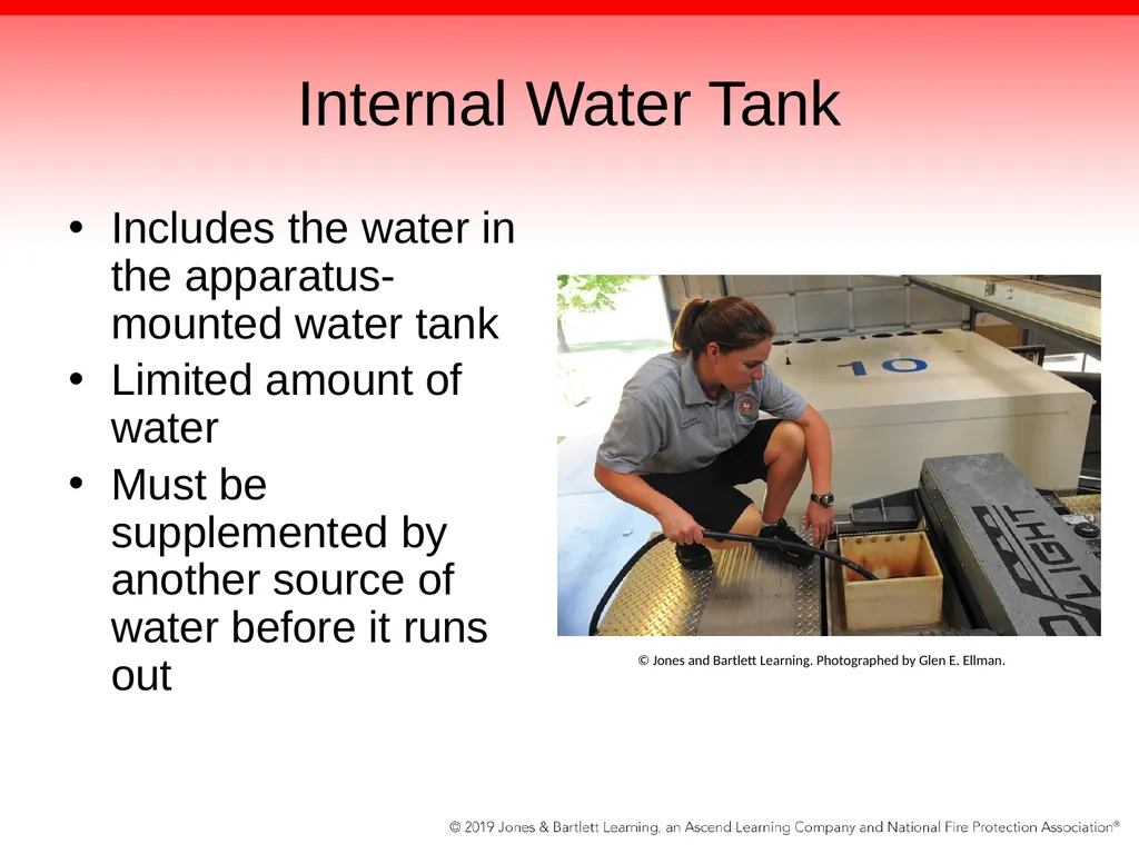
Internal Water Tank Includes the water in the apparatus-mounted water tank
Limited amount of water
Must be supplemented by another source of water before it runs out © Jones and Bartlett Learning. Photographed by Glen E. Ellman.<br>
Limited amount of water
Must be supplemented by another source of water before it runs out © Jones and Bartlett Learning. Photographed by Glen E. Ellman.<br>
08
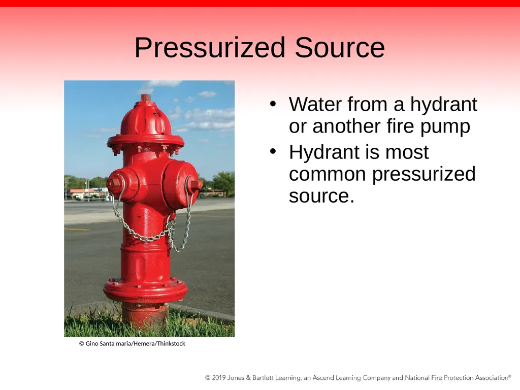
Pressurized Source Water from a hydrant or another fire pump
Hydrant is most common pressurized source. © Gino Santa maria/Hemera/Thinkstock<br>
Hydrant is most common pressurized source. © Gino Santa maria/Hemera/Thinkstock<br>
09
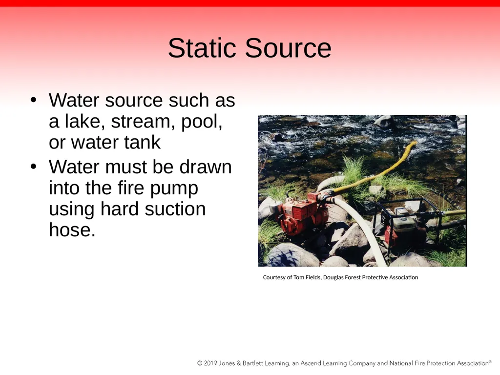
Static Source Water source such as a lake, stream, pool, or water tank
Water must be drawn into the fire pump using hard suction hose. Courtesy of Tom Fields, Douglas Forest Protective Association<br>
Water must be drawn into the fire pump using hard suction hose. Courtesy of Tom Fields, Douglas Forest Protective Association<br>
10
Fire Pump Operators Driver/operator must also be capable of transferring water from an internal water tank supply to an external source.
Practice is referred to as a changeover operation.<br>
Practice is referred to as a changeover operation.<br>
11
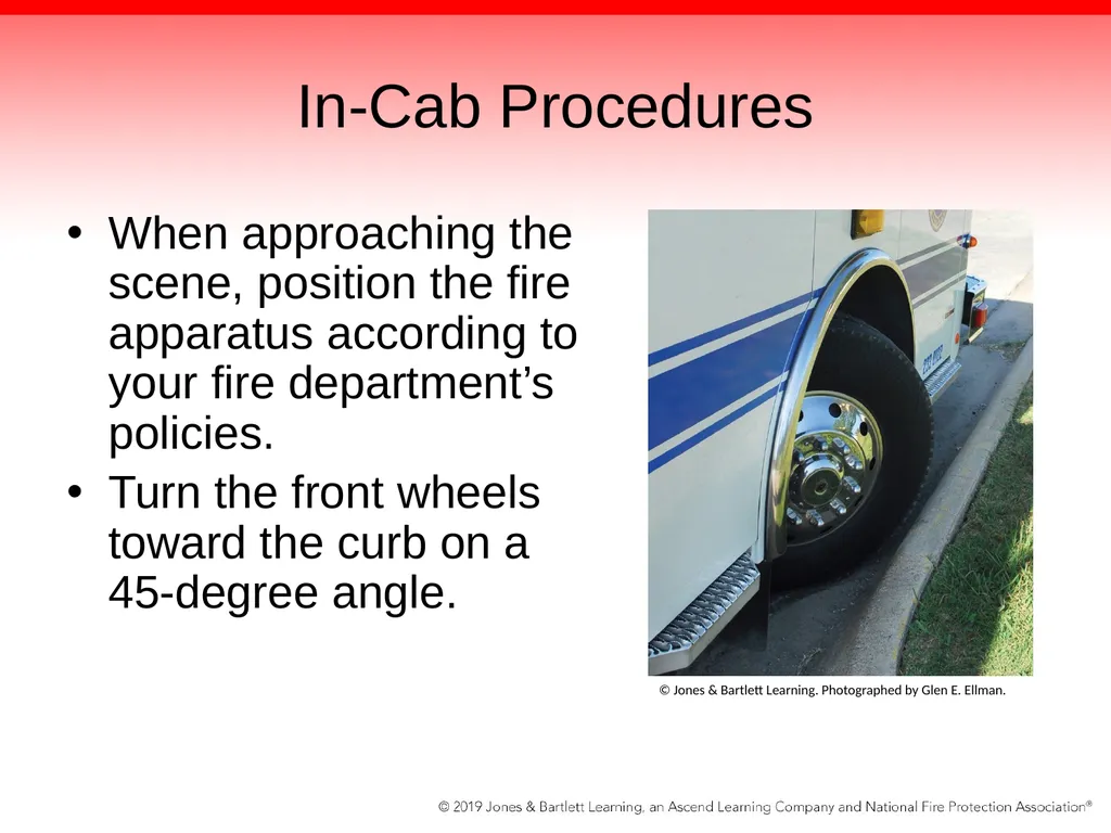
In-Cab Procedures When approaching the scene, position the fire apparatus according to your fire department’s policies.
Turn the front wheels toward the curb on a 45-degree angle. © Jones & Bartlett Learning. Photographed by Glen E. Ellman.<br>
Turn the front wheels toward the curb on a 45-degree angle. © Jones & Bartlett Learning. Photographed by Glen E. Ellman.<br>
12
In-Cab Procedures Turn off all unnecessary emergency lighting.
Place the transmission into neutral or park, based on the fire apparatus.
Apply the parking brake.
Change the fire apparatus’ transmission from the “road” position to the “pump” position.<br>
Place the transmission into neutral or park, based on the fire apparatus.
Apply the parking brake.
Change the fire apparatus’ transmission from the “road” position to the “pump” position.<br>
13
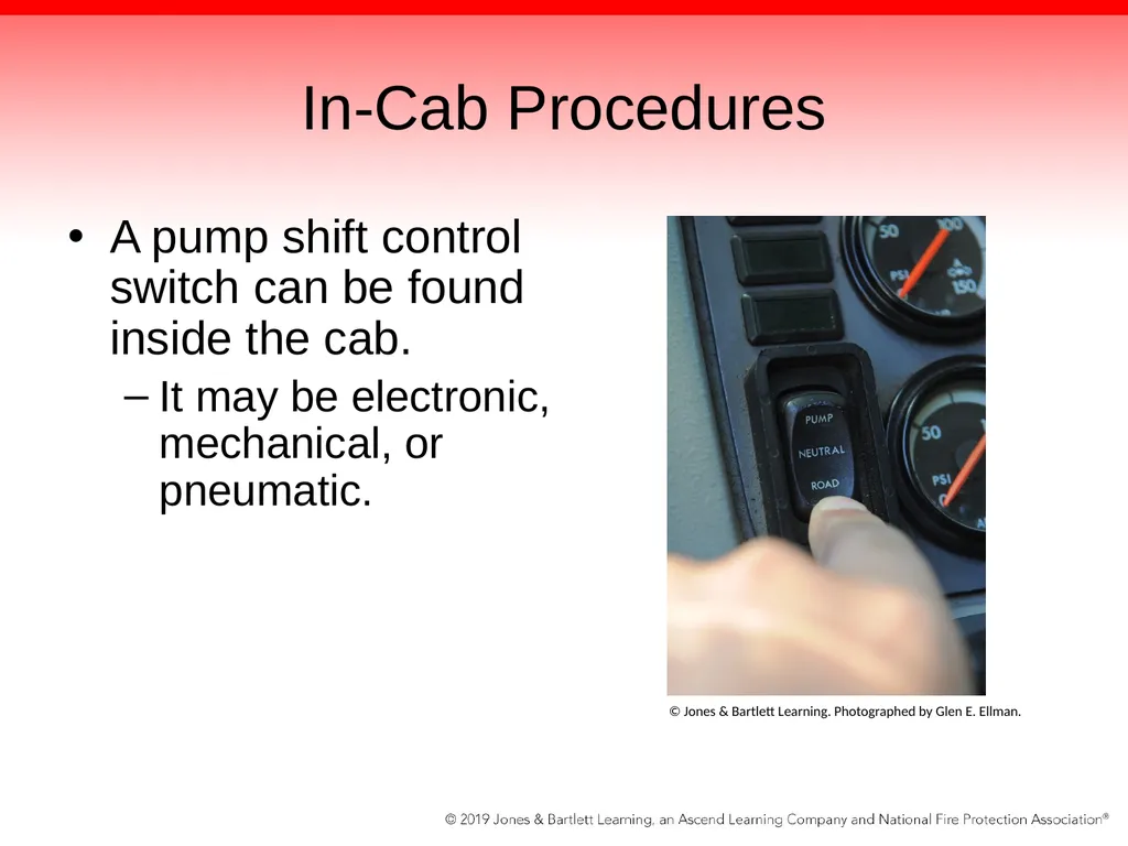
In-Cab Procedures A pump shift control switch can be found inside the cab.
It may be electronic, mechanical, or pneumatic. © Jones & Bartlett Learning. Photographed by Glen E. Ellman.<br>
It may be electronic, mechanical, or pneumatic. © Jones & Bartlett Learning. Photographed by Glen E. Ellman.<br>
14
In-Cab Procedures Place the apparatus transmission into drive.
A light near the pump shift control switch or in the cab will illuminate.
Revolutions per minute (rpm) and speed of the fire apparatus should increase slightly.
For push-button transmission selectors, check the transmission selector display to verify that the transmission is in the correct gear (1:1, which is 4th gear) and that the apparatus is in pump.<br>
A light near the pump shift control switch or in the cab will illuminate.
Revolutions per minute (rpm) and speed of the fire apparatus should increase slightly.
For push-button transmission selectors, check the transmission selector display to verify that the transmission is in the correct gear (1:1, which is 4th gear) and that the apparatus is in pump.<br>
15
Exiting the Cab Chock the wheels of the fire apparatus.
Follow your department’s SOP/SOG and manufacturer’s recommendations regarding which wheels to chock.
Usually, two wheel chocks are placed against the rear driver’s side tires.<br>
Follow your department’s SOP/SOG and manufacturer’s recommendations regarding which wheels to chock.
Usually, two wheel chocks are placed against the rear driver’s side tires.<br>
16
Exiting the Cab Circulate water into the pump.
Open the “tank to pump” valve.
Valve allows water to flow from onboard tank into pump.
Valve may be called “Water” or “Tank to Pump.”
Remove any air inside the centrifugal pump.
Valve may be called “Recirculation Valve” or “Tank Refill.”
Procedure ensures water flow from onboard tank to pump, and then out from pump back into tank.<br>
Open the “tank to pump” valve.
Valve allows water to flow from onboard tank into pump.
Valve may be called “Water” or “Tank to Pump.”
Remove any air inside the centrifugal pump.
Valve may be called “Recirculation Valve” or “Tank Refill.”
Procedure ensures water flow from onboard tank to pump, and then out from pump back into tank.<br>
17
Internal Water Tank Once fire pump is engaged, driver/operator is ready to supply the attack lines using the internal water tank.
Provides for quick deployment of water
Limited by amount of water carried on apparatus
Typically used to fight small fires
If more water is needed, an external water supply from pressurized or static source must be used.<br>
Provides for quick deployment of water
Limited by amount of water carried on apparatus
Typically used to fight small fires
If more water is needed, an external water supply from pressurized or static source must be used.<br>
18
Pressurized Water Sources Fire hose evolutions are critical in the driver/operator’s success.
Driver/operator should know the pressures at which the lines need to be supplied.
Ensure that the lines are properly flaked out before they are charged with water pressure.
Hose evolutions are divided into supply line operations and attack line operations.<br>
Driver/operator should know the pressures at which the lines need to be supplied.
Ensure that the lines are properly flaked out before they are charged with water pressure.
Hose evolutions are divided into supply line operations and attack line operations.<br>
19
Supply Line Evolutions To deliver water from a hydrant or alternative water source to an attack pumper
Involves laying a hoseline with a moving vehicle or dropping a continuous line of hose out of a bed as the fire apparatus moves forward
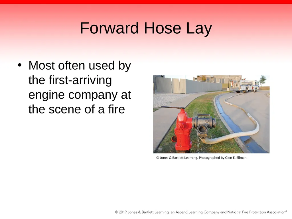
Forward lay starts at the hydrant and proceeds toward the fire.
Reverse lay involves laying the hose from the fire to the hydrant.<br>
Involves laying a hoseline with a moving vehicle or dropping a continuous line of hose out of a bed as the fire apparatus moves forward
Forward lay starts at the hydrant and proceeds toward the fire.
Reverse lay involves laying the hose from the fire to the hydrant.<br>
20
Forward Hose Lay Most often used by the first-arriving engine company at the scene of a fire © Jones & Bartlett Learning. Photographed by Glen E. Ellman.<br>
21
Forward Hose Lay Driver/operator stops the engine at a hydrant close to the fire scene.
Fire fighter dismounts the fire apparatus and wraps the hose around the hydrant or places a strap around it to secure the hose in place.
Fire fighter signals the driver/operator to continue on to the fire by stating, “Driver, go.”
Driver/operator proceeds to the fire scene no faster than 15 mph (25 km/h).<br>
Fire fighter dismounts the fire apparatus and wraps the hose around the hydrant or places a strap around it to secure the hose in place.
Fire fighter signals the driver/operator to continue on to the fire by stating, “Driver, go.”
Driver/operator proceeds to the fire scene no faster than 15 mph (25 km/h).<br>
22
Forward Hose Lay At fire scene, disconnect the supply line from the hose bed, connect it to the pump, and call for the supply line to be charged with water.
Allows the engine company to establish a water supply without assistance from an additional company<br>
Allows the engine company to establish a water supply without assistance from an additional company<br>
23
Forward Hose Lay Can be performed using medium-diameter hose (MDH; 2½ inch [65 mm] or 3 inch [77 mm]) or large-diameter hose (LDH; 3½ inch [90 mm] and larger)
If the fire hydrant is close to the fire, it may supply a sufficient quantity of water to charge the lines (rather than using an interim supply engine to boost the flow).<br>
If the fire hydrant is close to the fire, it may supply a sufficient quantity of water to charge the lines (rather than using an interim supply engine to boost the flow).<br>
24
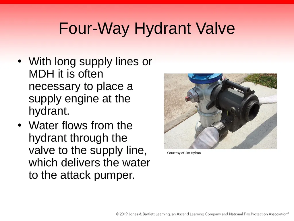
Four-Way Hydrant Valve With long supply lines or MDH it is often necessary to place a supply engine at the hydrant.
Water flows from the hydrant through the valve to the supply line, which delivers the water to the attack pumper. Courtesy of Jim Hylton<br>
Water flows from the hydrant through the valve to the supply line, which delivers the water to the attack pumper. Courtesy of Jim Hylton<br>
25
Four-Way Hydrant Valve Second engine can then hook up to the four-way valve and redirect the flow by changing the position of the valve.
Operation can be accomplished without uncoupling any lines or interrupting the flow.<br>
Operation can be accomplished without uncoupling any lines or interrupting the flow.<br>
26
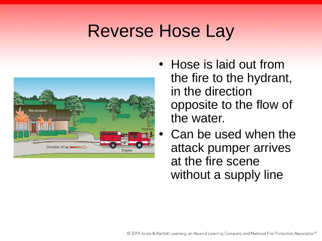
Reverse Hose Lay Hose is laid out from the fire to the hydrant, in the direction opposite to the flow of the water.
Can be used when the attack pumper arrives at the fire scene without a supply line<br>
Can be used when the attack pumper arrives at the fire scene without a supply line<br>
27
Reverse Hose Lay Also used to supply the attack pumper directly through the hydrant
May be a standard tactic in areas where sufficient hydrants are available and additional companies that can assist in establishing a water supply will arrive quickly<br>
May be a standard tactic in areas where sufficient hydrants are available and additional companies that can assist in establishing a water supply will arrive quickly<br>
28
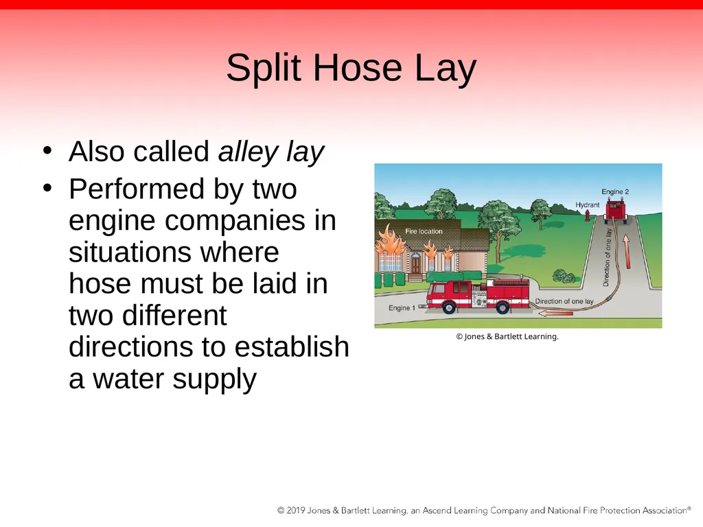
Split Hose Lay Also called alley lay
Performed by two engine companies in situations where hose must be laid in two different directions to establish a water supply © Jones & Bartlett Learning.<br>
Performed by two engine companies in situations where hose must be laid in two different directions to establish a water supply © Jones & Bartlett Learning.<br>
29
Split Hose Lay Attack pumper drops the end of its supply hose at the corner of the street and performs a forward lay toward the fire.
Secure the end of the supply line to a fixed object to keep it from dragging behind the attack pumper.
When the supply engine gets to the intersection, stop and pull off enough hose to connect to the end of this supply line, and then perform a reverse lay to the hydrant or water source.<br>
Secure the end of the supply line to a fixed object to keep it from dragging behind the attack pumper.
When the supply engine gets to the intersection, stop and pull off enough hose to connect to the end of this supply line, and then perform a reverse lay to the hydrant or water source.<br>
30
Split Hose Lay Often requires coordination by two-way radio
Attack pumper must advise the supply engine of the plan and indicate where the end of the supply line is being dropped and anchored.
Does not necessarily require split hose beds
Can be performed with or without split beds if the necessary adapters are used<br>
Attack pumper must advise the supply engine of the plan and indicate where the end of the supply line is being dropped and anchored.
Does not necessarily require split hose beds
Can be performed with or without split beds if the necessary adapters are used<br>
31
Connecting a Fire Department Engine to a Water Supply When an engine sets up at a hydrant, supply hose must be used to deliver the water from the hydrant to the engine.
Supply line is intended to deliver as much water as possible over a short distance.
In most cases, a soft suction hose is used to connect directly to a hydrant.
Connection can also be made with a short length of large-diameter supply hose.<br>
Supply line is intended to deliver as much water as possible over a short distance.
In most cases, a soft suction hose is used to connect directly to a hydrant.
Connection can also be made with a short length of large-diameter supply hose.<br>
32
Securing a Water Source Securing a water source is one of your primary responsibilities.
Before leaving the station, have a working knowledge of water sources at or close to the scene.
Generally it is the fire officer’s call whether you will lay a supply line to the incident.
Sometimes a hydrant may be located in close proximity to the building on fire.<br>
Before leaving the station, have a working knowledge of water sources at or close to the scene.
Generally it is the fire officer’s call whether you will lay a supply line to the incident.
Sometimes a hydrant may be located in close proximity to the building on fire.<br>
33
Hand Lays If you must create a hand lay, consider the following:
What is the distance between the fire apparatus and the closest hydrant?
What is the best hose to make the connection?
How long will this step take to complete?<br>
What is the distance between the fire apparatus and the closest hydrant?
What is the best hose to make the connection?
How long will this step take to complete?<br>
34
Hand Lays To determine how far away the closest hydrant is, reference the map book or eyeball the estimated distance from your pump intake to the hydrant.
Know how long each line found on the fire apparatus is and how many of these lines the fire apparatus carries.<br>
Know how long each line found on the fire apparatus is and how many of these lines the fire apparatus carries.<br>
35
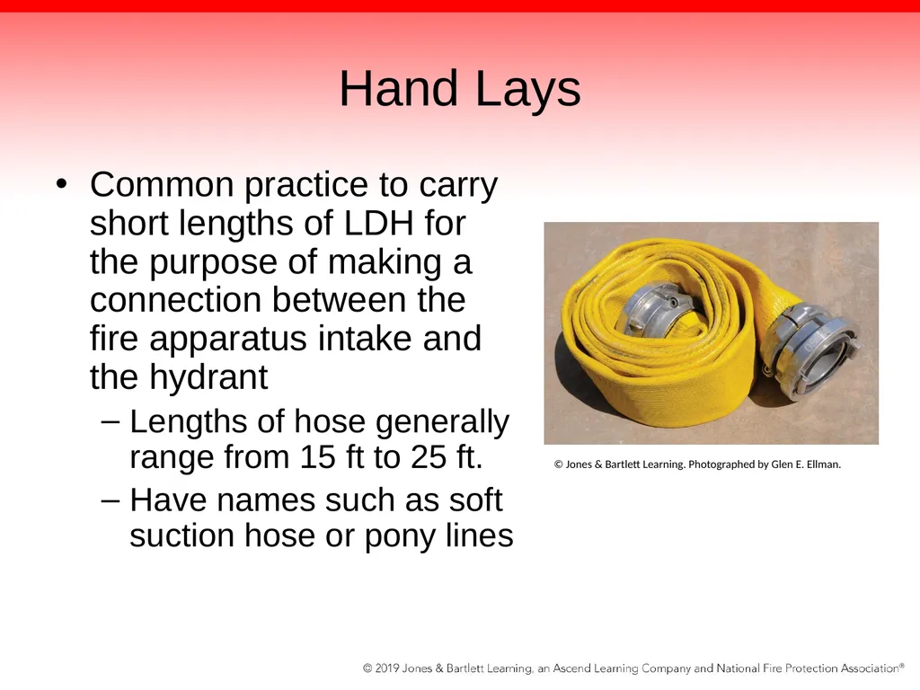
Hand Lays Common practice to carry short lengths of LDH for the purpose of making a connection between the fire apparatus intake and the hydrant
Lengths of hose generally range from 15 ft to 25 ft.
Have names such as soft suction hose or pony lines © Jones & Bartlett Learning. Photographed by Glen E. Ellman.<br>
Lengths of hose generally range from 15 ft to 25 ft.
Have names such as soft suction hose or pony lines © Jones & Bartlett Learning. Photographed by Glen E. Ellman.<br>
36
Hand Lays Some fire departments may carry reduced-length 3-inch (77-mm) or 2½-inch (65-mm) hose for refilling the onboard tank from a hydrant.
If the hydrant is 60 ft (18 m) away, using the shorter LDH lines most likely will not be an option.<br>
If the hydrant is 60 ft (18 m) away, using the shorter LDH lines most likely will not be an option.<br>
37
Hand Lays When considering how long the hand lay will take to accomplish, take into account:
The distance from the fire apparatus to the hydrant
The choice of hose
Any possible obstacles in the way to deploy the hose
When obtaining a water source, consider the need to double-tap a hydrant.<br>
The distance from the fire apparatus to the hydrant
The choice of hose
Any possible obstacles in the way to deploy the hose
When obtaining a water source, consider the need to double-tap a hydrant.<br>
38
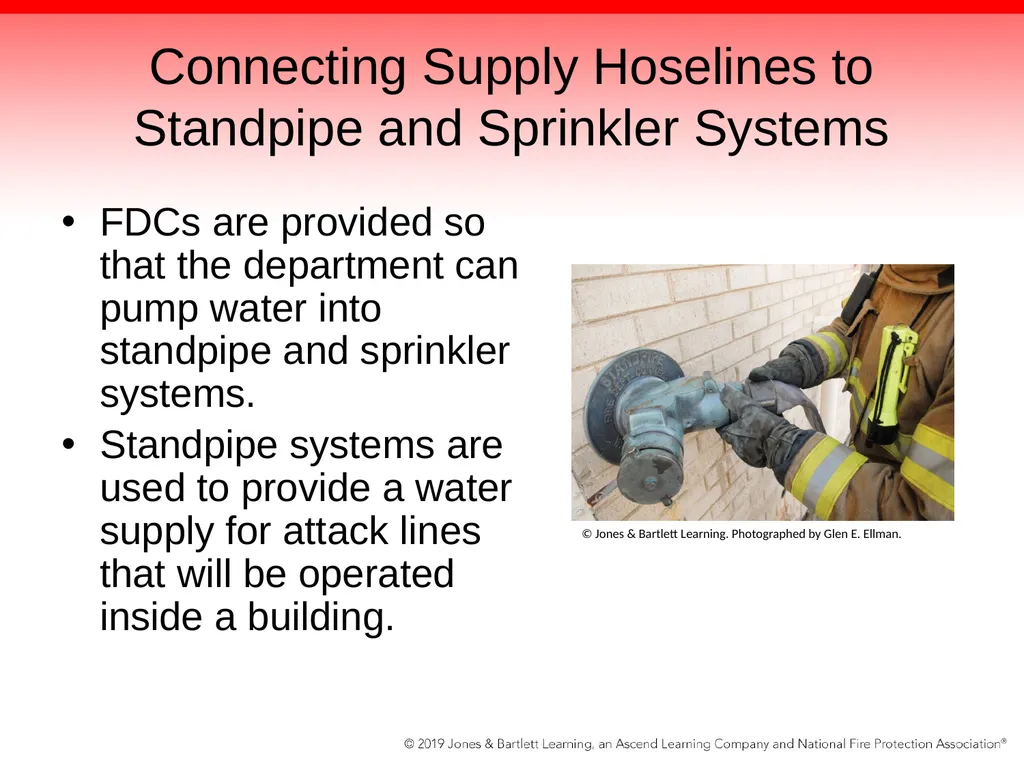
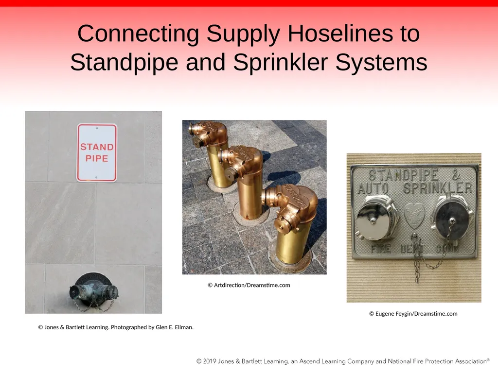
Connecting Supply Hoselines to Standpipe and Sprinkler Systems FDCs are provided so that the department can pump water into standpipe and sprinkler systems.
Standpipe systems are used to provide a water supply for attack lines that will be operated inside a building. © Jones & Bartlett Learning. Photographed by Glen E. Ellman.<br>
Standpipe systems are used to provide a water supply for attack lines that will be operated inside a building. © Jones & Bartlett Learning. Photographed by Glen E. Ellman.<br>
39
Connecting Supply Hoselines to Standpipe and Sprinkler Systems Two general types of standpipes
Dry system depends on the fire department to provide all of the water.
Wet system has a built-in water supply, but the FDC is provided to deliver a higher flow or to boost the pressure.<br>
Dry system depends on the fire department to provide all of the water.
Wet system has a built-in water supply, but the FDC is provided to deliver a higher flow or to boost the pressure.<br>
40
Connecting Supply Hoselines to Standpipe and Sprinkler Systems Pressure requirements for standpipe systems depend on the height of water use in the building.
Private fire protection systems may be present in the building.
Need a complete and thorough understanding of these systems
FDC can be free standing or wall mounted.<br>
Private fire protection systems may be present in the building.
Need a complete and thorough understanding of these systems
FDC can be free standing or wall mounted.<br>
41
Connecting Supply Hoselines to Standpipe and Sprinkler Systems © Jones & Bartlett Learning. Photographed by Glen E. Ellman. © Artdirection/Dreamstime.com © Eugene Feygin/Dreamstime.com<br>
42
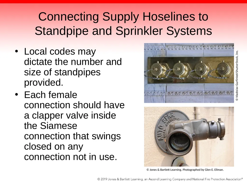
Connecting Supply Hoselines to Standpipe and Sprinkler Systems Local codes may dictate the number and size of standpipes provided.
Each female connection should have a clapper valve inside the Siamese connection that swings closed on any connection not in use. © Jones & Bartlett Learning. Photographed by Glen E. Ellman. © Vladislav Gurfinkel/ShutterStock, Inc.<br>
Each female connection should have a clapper valve inside the Siamese connection that swings closed on any connection not in use. © Jones & Bartlett Learning. Photographed by Glen E. Ellman. © Vladislav Gurfinkel/ShutterStock, Inc.<br>
43
Connecting Supply Hoselines to Standpipe and Sprinkler Systems If the exterior FDC connection is damaged so that a connection cannot be made, hook it up to the standpipe on the building’s first floor.
Connect the engine to the sprinkler/standpipe; your SOPs may specify when to supply the standpipe.
Wet versus dry systems are dictated by state and local codes<br>
Connect the engine to the sprinkler/standpipe; your SOPs may specify when to supply the standpipe.
Wet versus dry systems are dictated by state and local codes<br>
44
Performing a Changeover When arriving at a scene, you may need to supply attack lines from an onboard tank, then have a supply line laid to the pump from another apparatus or a hand-laid supply line.
Supplying attack lines from an onboard tank is limited by the water in the tank.
Tank water lasts only so long.
Supply line is needed to sustain a fire attack for longer time.<br>
Supplying attack lines from an onboard tank is limited by the water in the tank.
Tank water lasts only so long.
Supply line is needed to sustain a fire attack for longer time.<br>
45
Performing a Changeover During changeover, driver/operator switches from onboard tank to external source.
Goal: to make changeover before running out of water in tank, with least pressure fluctuation for crew on nozzle
Overpressurizing the attack line causes fire fighters to lose control, causing an unsafe situation.<br>
Goal: to make changeover before running out of water in tank, with least pressure fluctuation for crew on nozzle
Overpressurizing the attack line causes fire fighters to lose control, causing an unsafe situation.<br>
46
Performing a Changeover Driver/operator needs to supply attack lines with correct pressure constantly to ensure safe operation.
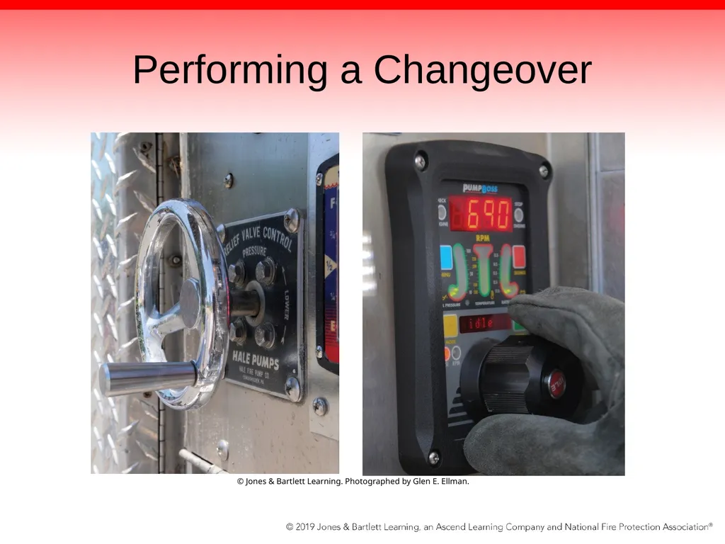
Pressure relief valve and pressure governor assist in this task.
Transfer valve may be needed in a multistage pump.<br>
Pressure relief valve and pressure governor assist in this task.
Transfer valve may be needed in a multistage pump.<br>
47
Performing a Changeover © Jones & Bartlett Learning. Photographed by Glen E. Ellman.<br>
48
Performing a Changeover Factors to consider before changeover
How much water is currently in the tank?
What flow rate (gpm) and pressure (psi) are used by the crew on the attack line?
What is the incoming pressure from the supply line?
What is the setting of the pressure control device?<br>
How much water is currently in the tank?
What flow rate (gpm) and pressure (psi) are used by the crew on the attack line?
What is the incoming pressure from the supply line?
What is the setting of the pressure control device?<br>
49
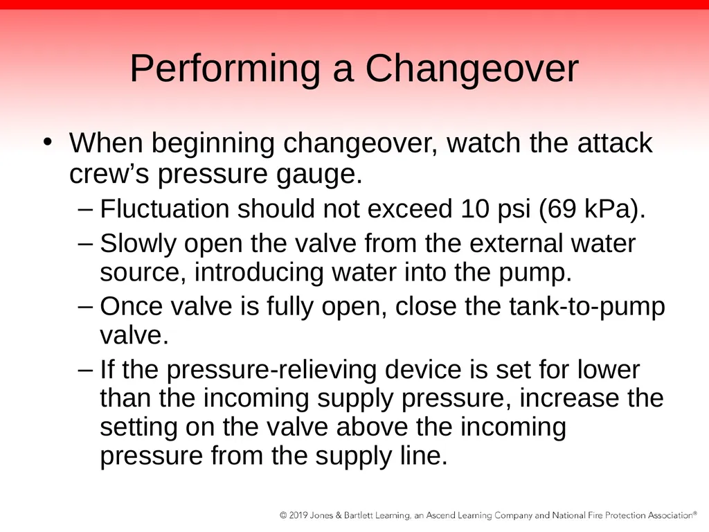
Performing a Changeover When beginning changeover, watch the attack crew’s pressure gauge.
Fluctuation should not exceed 10 psi (69 kPa).
Slowly open the valve from the external water source, introducing water into the pump.
Once valve is fully open, close the tank-to-pump valve.
If the pressure-relieving device is set for lower than the incoming supply pressure, increase the setting on the valve above the incoming pressure from the supply line.<br>
Fluctuation should not exceed 10 psi (69 kPa).
Slowly open the valve from the external water source, introducing water into the pump.
Once valve is fully open, close the tank-to-pump valve.
If the pressure-relieving device is set for lower than the incoming supply pressure, increase the setting on the valve above the incoming pressure from the supply line.<br>
50
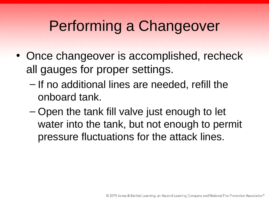
Performing a Changeover Once changeover is accomplished, recheck all gauges for proper settings.
If no additional lines are needed, refill the onboard tank.
Open the tank fill valve just enough to let water into the tank, but not enough to permit pressure fluctuations for the attack lines.<br>
If no additional lines are needed, refill the onboard tank.
Open the tank fill valve just enough to let water into the tank, but not enough to permit pressure fluctuations for the attack lines.<br>
51
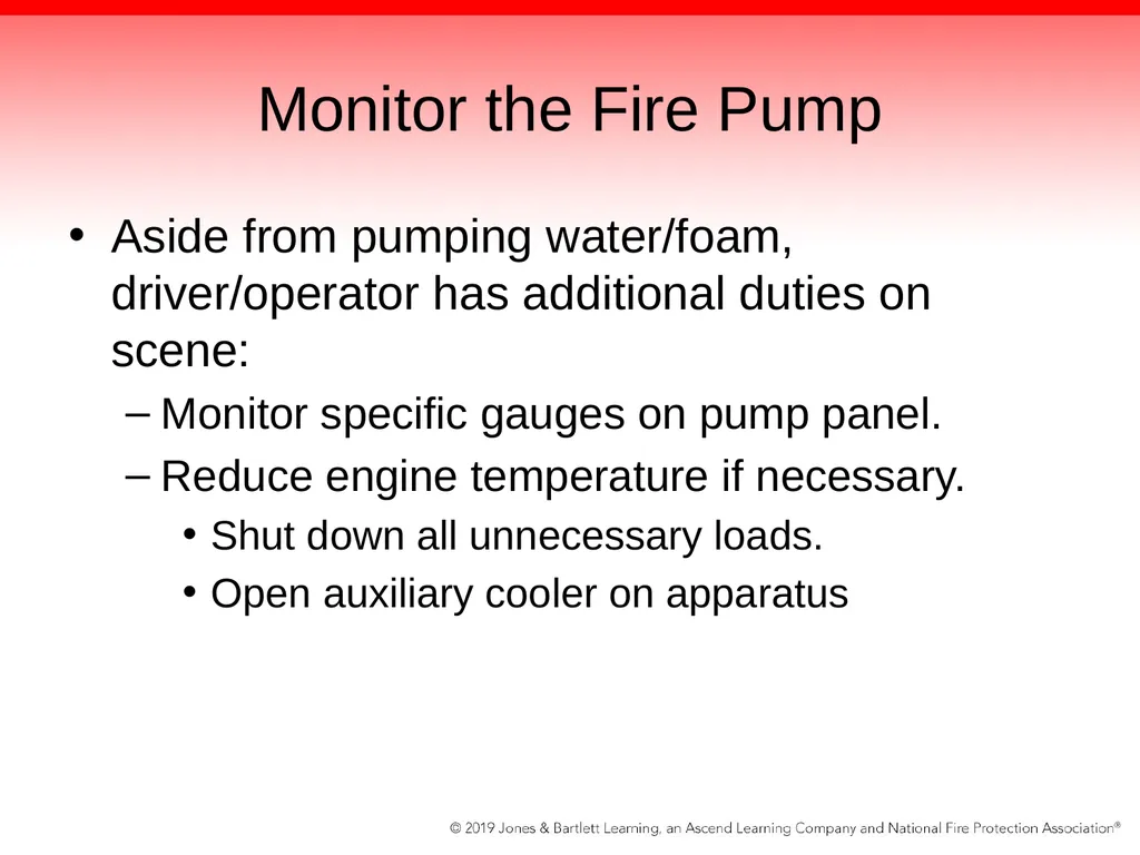
Monitor the Fire Pump Aside from pumping water/foam, driver/operator has additional duties on scene:
Monitor specific gauges on pump panel.
Reduce engine temperature if necessary.
Shut down all unnecessary loads.
Open auxiliary cooler on apparatus<br>
Monitor specific gauges on pump panel.
Reduce engine temperature if necessary.
Shut down all unnecessary loads.
Open auxiliary cooler on apparatus<br>
52
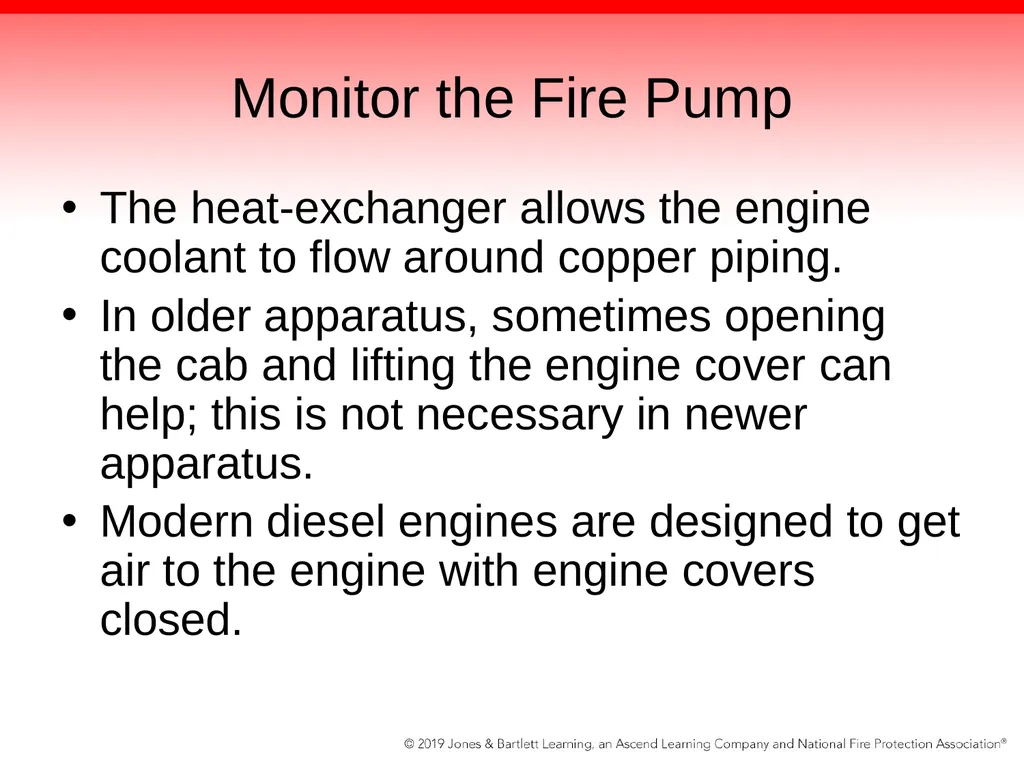
Monitor the Fire Pump The heat-exchanger allows the engine coolant to flow around copper piping.
In older apparatus, sometimes opening the cab and lifting the engine cover can help; this is not necessary in newer apparatus.
Modern diesel engines are designed to get air to the engine with engine covers closed.<br>
In older apparatus, sometimes opening the cab and lifting the engine cover can help; this is not necessary in newer apparatus.
Modern diesel engines are designed to get air to the engine with engine covers closed.<br>
53
Monitor the Fire Pump Final duty as the driver/operator on the fireground is to disengage the fire pump.
Always refer to and follow the manufacturer’s recommendations for your department’s specific apparatus.<br>
Always refer to and follow the manufacturer’s recommendations for your department’s specific apparatus.<br>
54
Operating Other Fixed Systems and Equipment Each apparatus will be equipped with tools and equipment according to its specific function on the emergency scene.
When operating emergency lights and/or other electrical appliances, engage the high idle switch, which sets the apparatus engine to 900–1100 rpm.<br>
When operating emergency lights and/or other electrical appliances, engage the high idle switch, which sets the apparatus engine to 900–1100 rpm.<br>
55
Operating Other Fixed Systems and Equipment NFPA 1901 requires that the vehicle’s electrical system be monitored by an automatic load management system.
System incorporates a load sequencer.
Activates electrical loads in a specific order to prevent overloading the electrical system
Also has load monitor
Driver/operator must know how to operate system correctly.<br>
System incorporates a load sequencer.
Activates electrical loads in a specific order to prevent overloading the electrical system
Also has load monitor
Driver/operator must know how to operate system correctly.<br>
56
Apparatus-Mounted Equipment Fire apparatus are equipped with a variety of apparatus-mounted equipment.
Not specific to every type of apparatus or fire department
Driver/operator is responsible for its maintenance and safe operation
Each apparatus manufacturer provides different systems and equipment on its apparatus, but they all share some common features.<br>
Not specific to every type of apparatus or fire department
Driver/operator is responsible for its maintenance and safe operation
Each apparatus manufacturer provides different systems and equipment on its apparatus, but they all share some common features.<br>
57
Apparatus-Mounted Equipment Driver/operator should not assume that a dependable supply of electricity will be provided at every emergency scene.
Some emergencies may occur in isolated areas.
Electricity may be provided by:
Inverter
Generator<br>
Some emergencies may occur in isolated areas.
Electricity may be provided by:
Inverter
Generator<br>
58
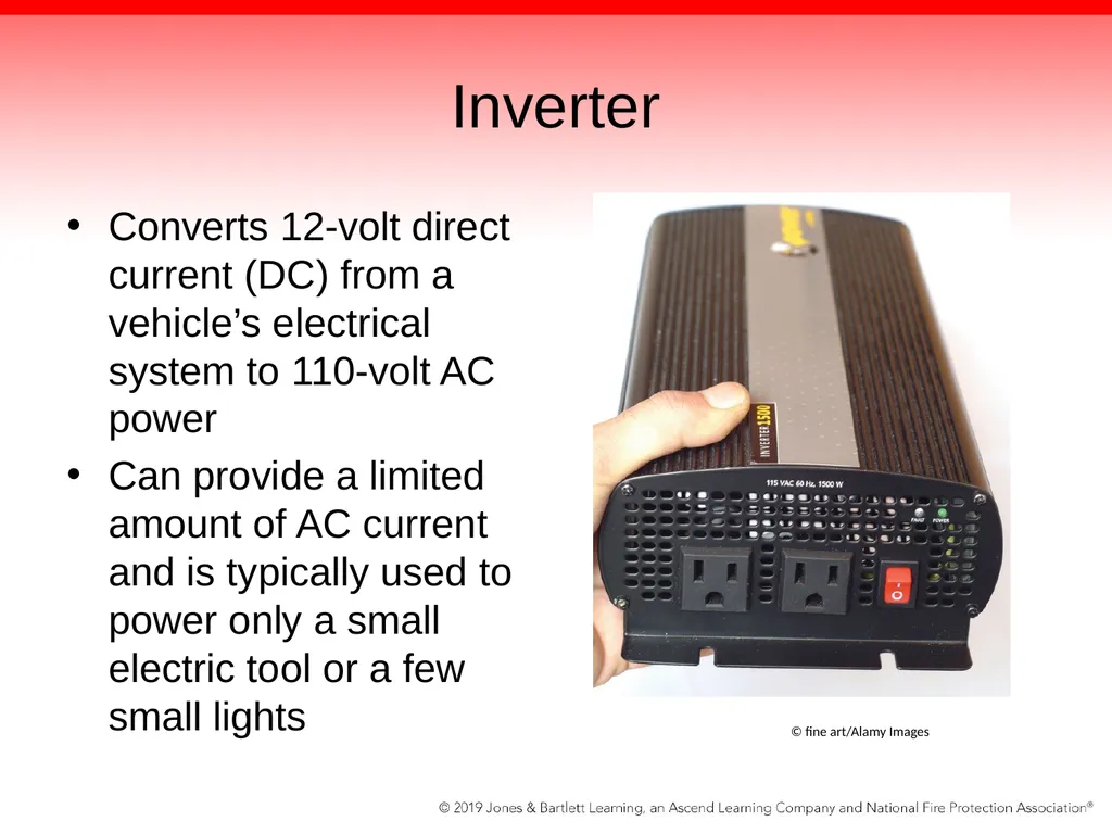
Inverter Converts 12-volt direct current (DC) from a vehicle’s electrical system to 110-volt AC power
Can provide a limited amount of AC current and is typically used to power only a small electric tool or a few small lights © fine art/Alamy Images<br>
Can provide a limited amount of AC current and is typically used to power only a small electric tool or a few small lights © fine art/Alamy Images<br>
59
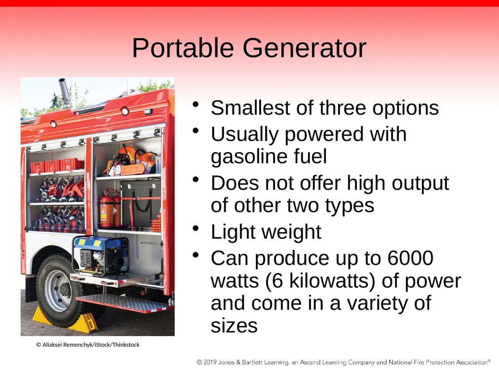
Portable Generator Smallest of three options
Usually powered with gasoline fuel
Does not offer high output of other two types
Light weight
Can produce up to 6000 watts (6 kilowatts) of power and come in a variety of sizes © Aliaksei Remenchyk/iStock/Thinkstock<br>
Usually powered with gasoline fuel
Does not offer high output of other two types
Light weight
Can produce up to 6000 watts (6 kilowatts) of power and come in a variety of sizes © Aliaksei Remenchyk/iStock/Thinkstock<br>
60
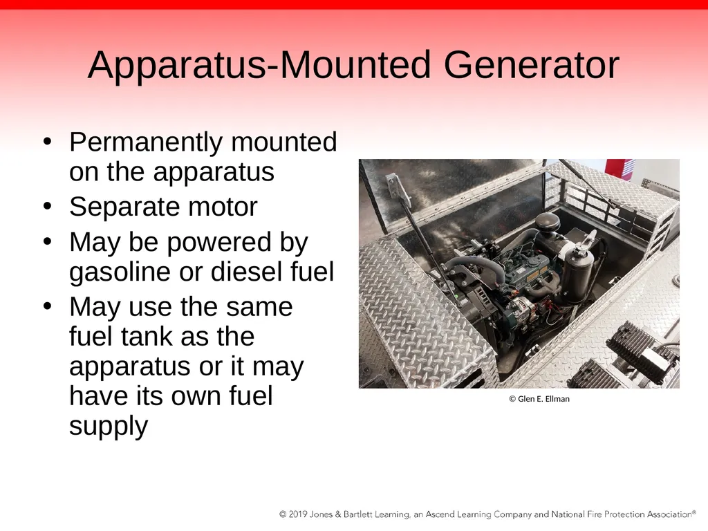
Apparatus-Mounted Generator Permanently mounted on the apparatus
Separate motor
May be powered by gasoline or diesel fuel
May use the same fuel tank as the apparatus or it may have its own fuel supply © Glen E. Ellman<br>
Separate motor
May be powered by gasoline or diesel fuel
May use the same fuel tank as the apparatus or it may have its own fuel supply © Glen E. Ellman<br>
61
Transmission-Driven Generator Powered by the vehicle’s motor and is driven by a power take-off (PTO) system
Apparatus’ engine powers the generator and any other system that is connected to its driveline.
May produce 25 kilowatts or more<br>
Apparatus’ engine powers the generator and any other system that is connected to its driveline.
May produce 25 kilowatts or more<br>
62
Scene Lighting Equipment Lighting for the night emergency scene and enable safe, efficient operations
Fire apparatus are equipped with a vast assortment of lighting equipment
Almost all fire apparatus have some capability to illuminate areas around the apparatus
Some lights have a different pattern than others (spotlights versus floodlights)
When used incorrectly, these lights can blind fire fighters or approaching vehicles<br>
Fire apparatus are equipped with a vast assortment of lighting equipment
Almost all fire apparatus have some capability to illuminate areas around the apparatus
Some lights have a different pattern than others (spotlights versus floodlights)
When used incorrectly, these lights can blind fire fighters or approaching vehicles<br>
63
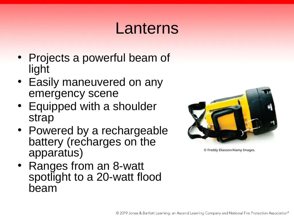
Lanterns Projects a powerful beam of light
Easily maneuvered on any emergency scene
Equipped with a shoulder strap
Powered by a rechargeable battery (recharges on the apparatus)
Ranges from an 8-watt spotlight to a 20-watt flood beam © Freddy Eliasson/Alamy Images.<br>
Easily maneuvered on any emergency scene
Equipped with a shoulder strap
Powered by a rechargeable battery (recharges on the apparatus)
Ranges from an 8-watt spotlight to a 20-watt flood beam © Freddy Eliasson/Alamy Images.<br>
64
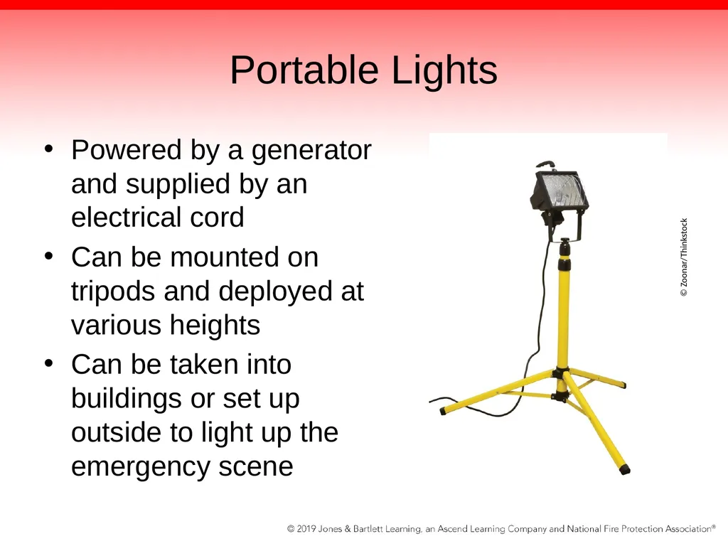
Portable Lights Powered by a generator and supplied by an electrical cord
Can be mounted on tripods and deployed at various heights
Can be taken into buildings or set up outside to light up the emergency scene © Zoonar/Thinkstock<br>
Can be mounted on tripods and deployed at various heights
Can be taken into buildings or set up outside to light up the emergency scene © Zoonar/Thinkstock<br>
65
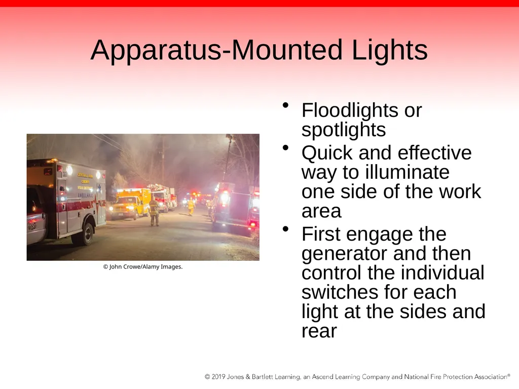
Apparatus-Mounted Lights Floodlights or spotlights
Quick and effective way to illuminate one side of the work area
First engage the generator and then control the individual switches for each light at the sides and rear © John Crowe/Alamy Images.<br>
Quick and effective way to illuminate one side of the work area
First engage the generator and then control the individual switches for each light at the sides and rear © John Crowe/Alamy Images.<br>
66
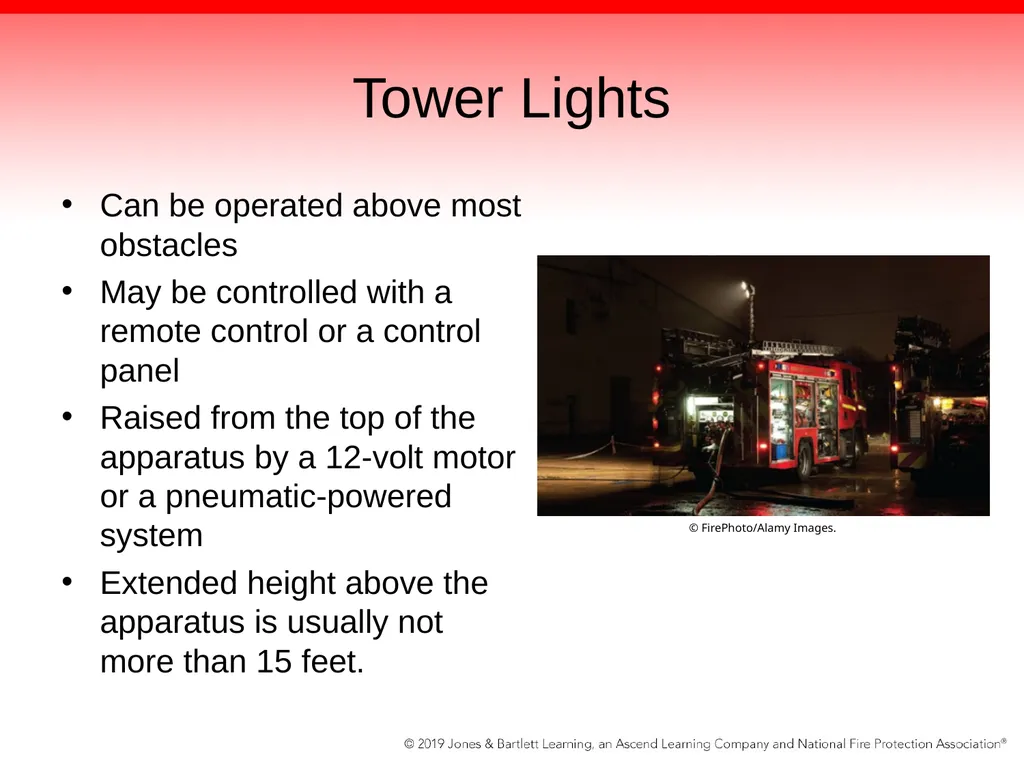
Tower Lights Can be operated above most obstacles
May be controlled with a remote control or a control panel
Raised from the top of the apparatus by a 12-volt motor or a pneumatic-powered system
Extended height above the apparatus is usually not more than 15 feet. © FirePhoto/Alamy Images.<br>
May be controlled with a remote control or a control panel
Raised from the top of the apparatus by a 12-volt motor or a pneumatic-powered system
Extended height above the apparatus is usually not more than 15 feet. © FirePhoto/Alamy Images.<br>
67
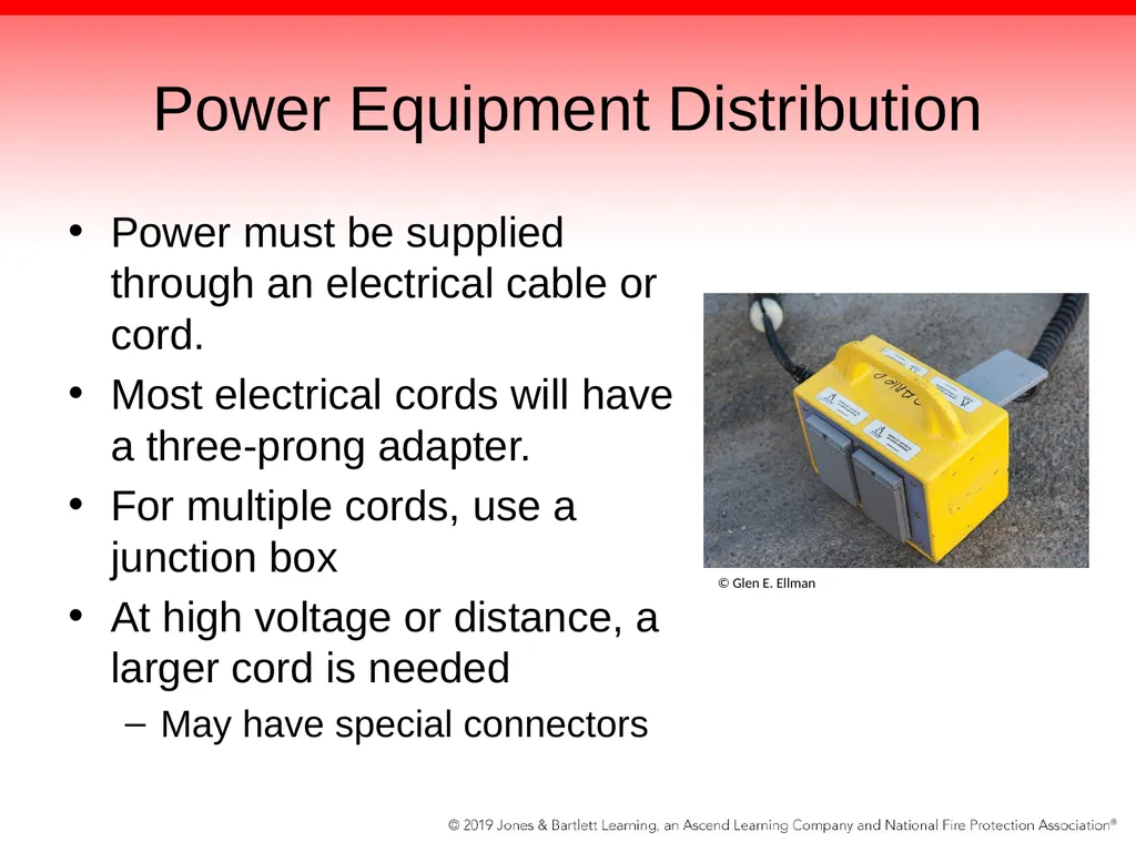
Power Equipment Distribution Power must be supplied through an electrical cable or cord.
Most electrical cords will have a three-prong adapter.
For multiple cords, use a junction box
At high voltage or distance, a larger cord is needed
May have special connectors © Glen E. Ellman<br>
Most electrical cords will have a three-prong adapter.
For multiple cords, use a junction box
At high voltage or distance, a larger cord is needed
May have special connectors © Glen E. Ellman<br>
68
Powered Rescue Tools Tools that receive power from the power unit component and generate energy used to perform one or more of the following functions: spreading, lifting, holding, crushing, pulling, or cutting
Power rescue tool system generally consists of a reservoir, fluid, a power unit, an enclosed system, and an actuator used to operate a power rescue tool.<br>
Power rescue tool system generally consists of a reservoir, fluid, a power unit, an enclosed system, and an actuator used to operate a power rescue tool.<br>
69
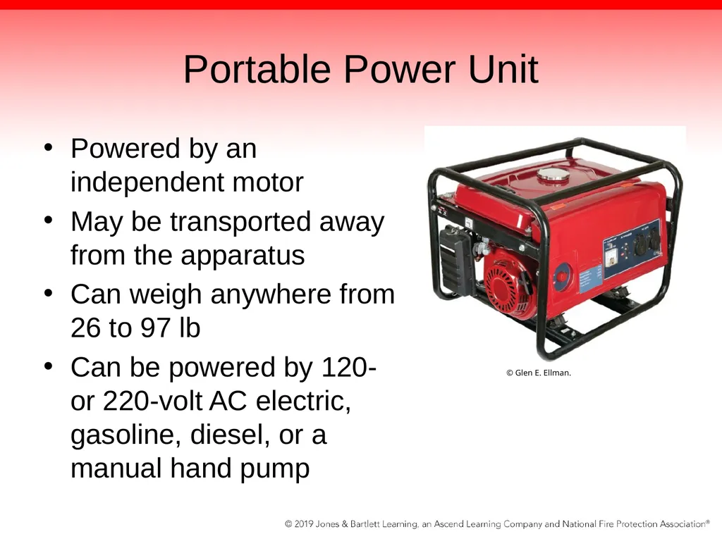
Portable Power Unit Powered by an independent motor
May be transported away from the apparatus
Can weigh anywhere from 26 to 97 lb
Can be powered by 120- or 220-volt AC electric, gasoline, diesel, or a manual hand pump © Glen E. Ellman.<br>
May be transported away from the apparatus
Can weigh anywhere from 26 to 97 lb
Can be powered by 120- or 220-volt AC electric, gasoline, diesel, or a manual hand pump © Glen E. Ellman.<br>
70
PTO-Driven Hydraulic Unit More powerful than most portable power units
Powered by vehicle’s engine through a PTO system and activated either by remote controls or by controls mounted inside the vehicle’s cab
Some are capable of operating up to six tools simultaneously.<br>
Powered by vehicle’s engine through a PTO system and activated either by remote controls or by controls mounted inside the vehicle’s cab
Some are capable of operating up to six tools simultaneously.<br>
71
Pressurized Fluid A positive-displacement pump is used to pressurize the hydraulic fluid in a powered rescue tool.
During operation, the pressurized hydraulic fluid will move from one section of the system to the other through hydraulic hoselines
Once the fluid is under pressure and traveling through the system, it operates an actuator
This force is then used to operate 1 of 4 types of hydraulic tools<br>
During operation, the pressurized hydraulic fluid will move from one section of the system to the other through hydraulic hoselines
Once the fluid is under pressure and traveling through the system, it operates an actuator
This force is then used to operate 1 of 4 types of hydraulic tools<br>
72
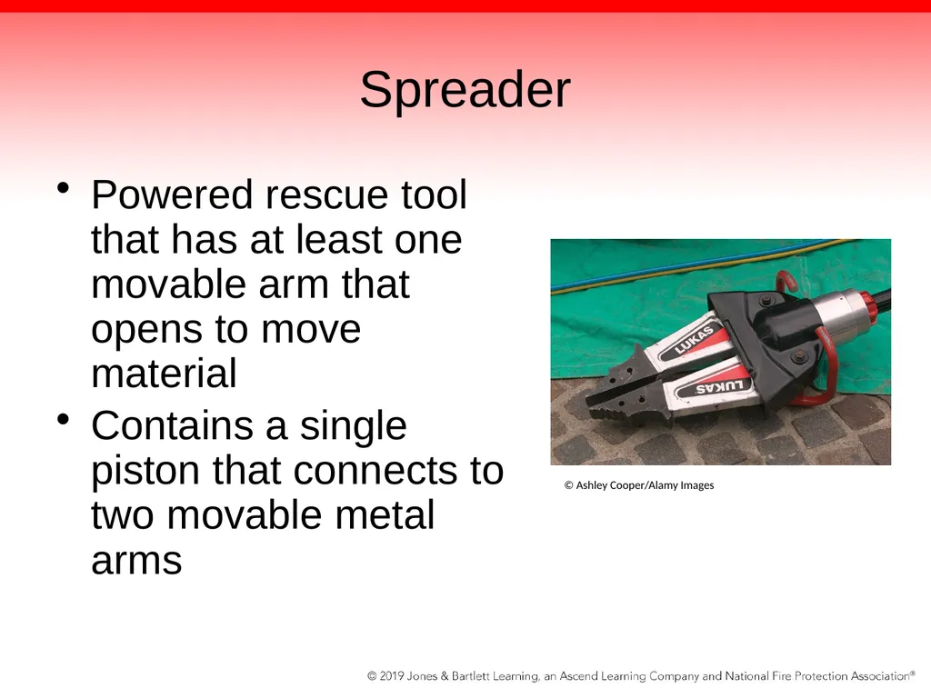
Spreader Powered rescue tool that has at least one movable arm that opens to move material
Contains a single piston that connects to two movable metal arms © Ashley Cooper/Alamy Images<br>
Contains a single piston that connects to two movable metal arms © Ashley Cooper/Alamy Images<br>
73
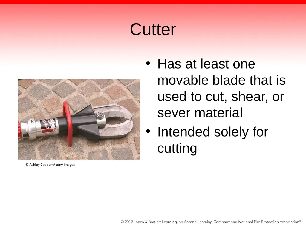
Cutter Has at least one movable blade that is used to cut, shear, or sever material
Intended solely for cutting © Ashley Cooper/Alamy Images<br>
Intended solely for cutting © Ashley Cooper/Alamy Images<br>
74
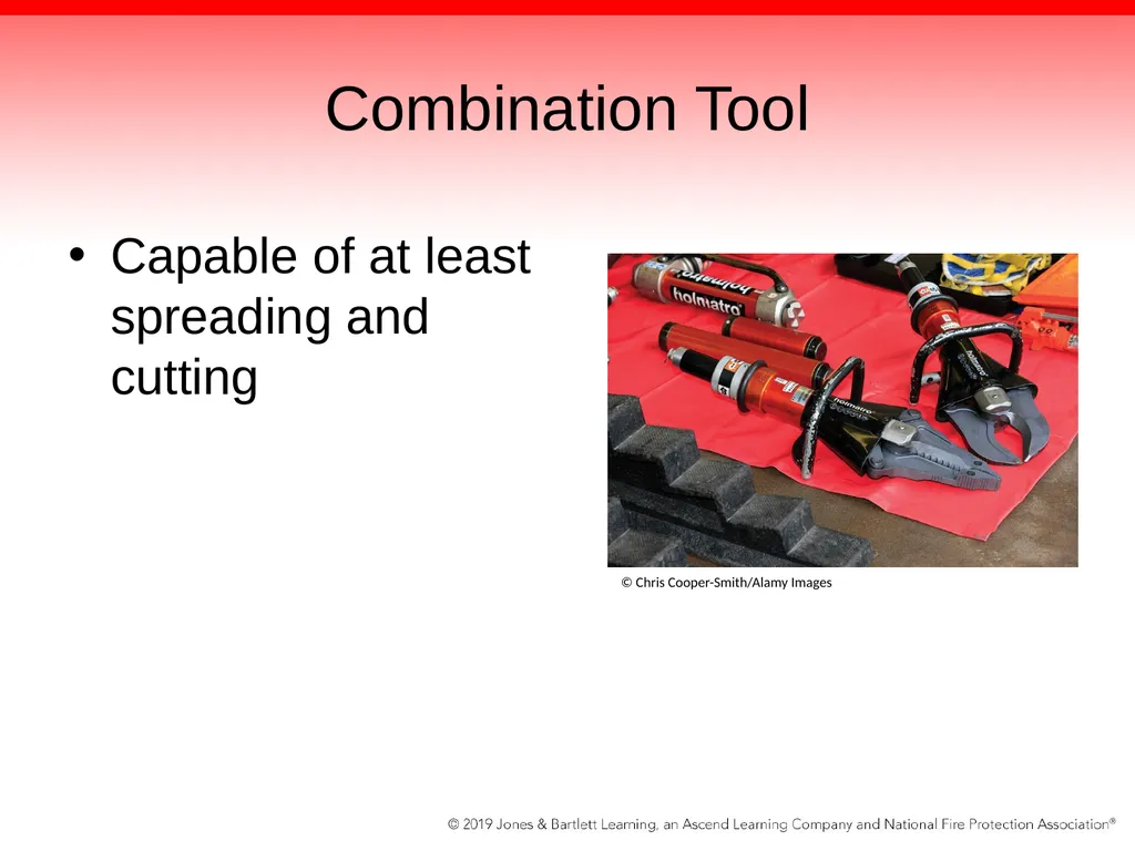
Combination Tool Capable of at least spreading and cutting © Chris Cooper-Smith/Alamy Images<br>
75
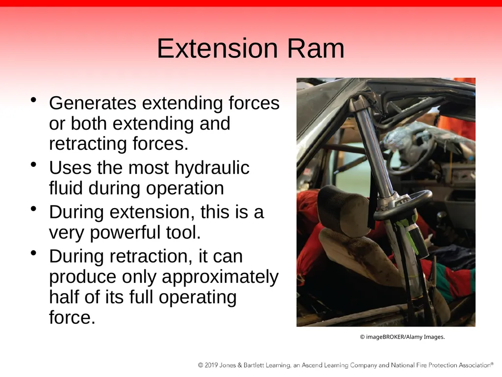
Extension Ram Generates extending forces or both extending and retracting forces.
Uses the most hydraulic fluid during operation
During extension, this is a very powerful tool.
During retraction, it can produce only approximately half of its full operating force. © imageBROKER/Alamy Images.<br>
Uses the most hydraulic fluid during operation
During extension, this is a very powerful tool.
During retraction, it can produce only approximately half of its full operating force. © imageBROKER/Alamy Images.<br>
76
Summary As the driver/operator, securing a water source upon arrival at the scene is one of your primary responsibilities.
Potential water sources include the internal water tank, a pressurized source, and a static source.
Before you leave the fire station to respond to the scene, you should have a working knowledge of water sources at or close to the scene.
Use a map book with hydrant locations in it
Become familiar with water sources within the response area<br>
Potential water sources include the internal water tank, a pressurized source, and a static source.
Before you leave the fire station to respond to the scene, you should have a working knowledge of water sources at or close to the scene.
Use a map book with hydrant locations in it
Become familiar with water sources within the response area<br>
77
Summary When your crew first arrives at the scene, you may initially need to supply attack lines from your onboard tank, but then have a supply line laid to your pump from another fire apparatus or via a hand-laid supply line.
Once the pumping operation is under way, you must monitor specific gauges on the pump panel to ensure that an adequate supply of water or foam is available for the duration of the incident.<br>
Once the pumping operation is under way, you must monitor specific gauges on the pump panel to ensure that an adequate supply of water or foam is available for the duration of the incident.<br>
78
Summary Fixed apparatus systems include generators to power lights and equipment.
Hydraulic systems may be powered by the apparatus or a separate power unit.<br>
Hydraulic systems may be powered by the apparatus or a separate power unit.<br>