
Chapter 7 Digital Filter Design CEN352, Dr. Nassim
Description: Chapter 7 Digital Filter Design CEN352, Dr. Nassim Ammour, King Saud University 1 FIR Filter Design. Frequency Sampling Design Method Fourier Transform Design Method 2. IIR Filter Design. 3. Application Bilinear Transformation Method Pole
Related Topics
Download Presentation
"Chapter 7 Digital Filter Design CEN352, Dr. Nassim" is the property of its rightful owner. Permission is granted to download and print the materials on this website for personal, non-commercial use only, and to display it on your personal computer provided you do not modify the materials and that you retain all copyright notices contained in the materials. By downloading content from our website, you accept the terms of this agreement.
Presentation Transcript
slide1. Chapter 7 Digital Filter Design CEN352, Dr. Nassim Ammour, King Saud University 1 FIR Filter Design. Frequency Sampling Design Method Fourier Transform Design Method 2. IIR Filter Design. 3. Application Bilinear Transformation Method Pole Zero Placement Method 60 –Hz Hum Eliminator ECG Pulse<br>
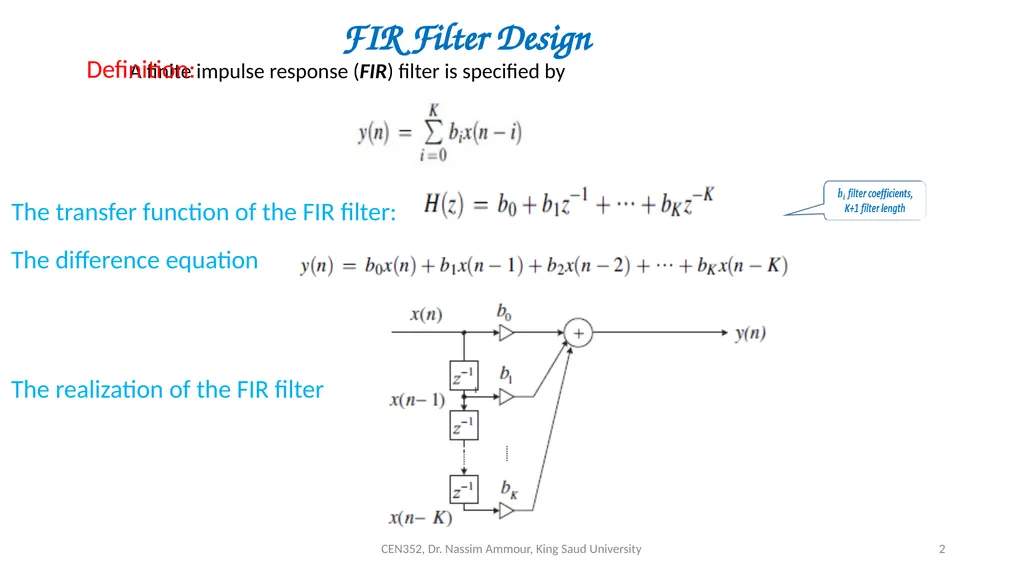
slide2. CEN352, Dr. Nassim Ammour, King Saud University 2 FIR Filter Design The transfer function of the FIR filter: The difference equation The realization of the FIR filter<br>
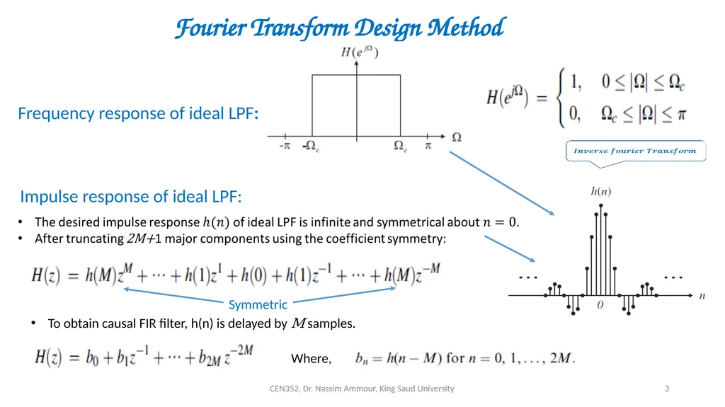
slide3. CEN352, Dr. Nassim Ammour, King Saud University 3 Fourier Transform Design Method Frequency response of ideal LPF: Impulse response of ideal LPF: To obtain causal FIR filter, h(n) is delayed by M samples. Where,<br>
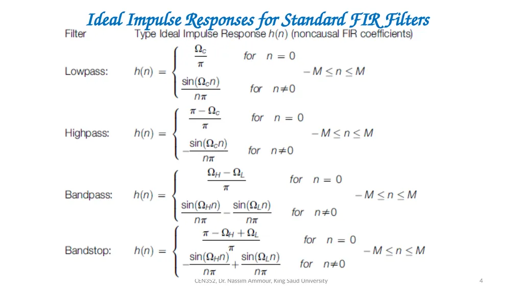
slide4. CEN352, Dr. Nassim Ammour, King Saud University 4 Ideal Impulse Responses for Standard FIR Filters<br>
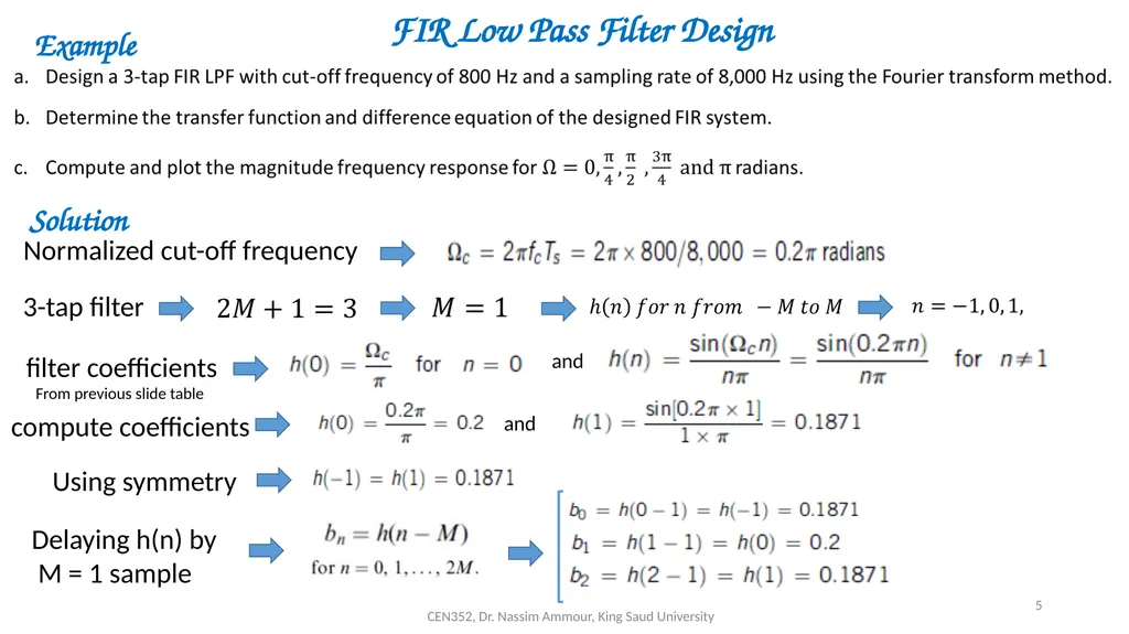
slide5. CEN352, Dr. Nassim Ammour, King Saud University 5 Example Solution FIR Low Pass Filter Design<br>
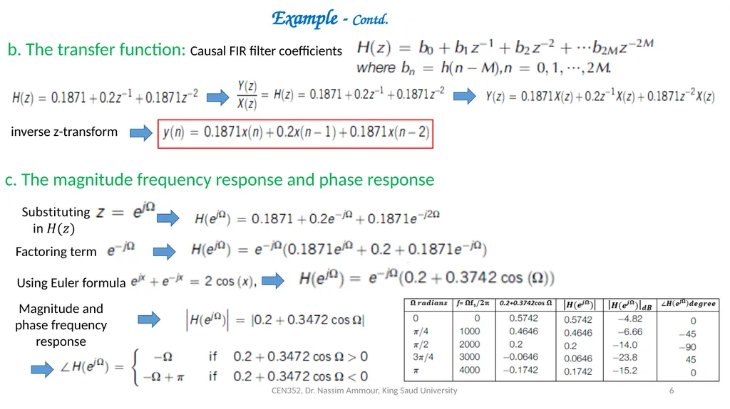
slide6. CEN352, Dr. Nassim Ammour, King Saud University 6 b. The transfer function: Causal FIR filter coefficients Example - Contd. inverse z-transform c. The magnitude frequency response and phase response Using Euler formula Magnitude and phase frequency
response<br>
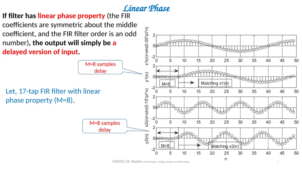
slide7. CEN352, Dr. Nassim Ammour, King Saud University 7 Linear Phase If filter has linear phase property (the FIR coefficients are symmetric about the middle coefficient, and the FIR filter order is an odd number), the output will simply be a delayed version of input. Let, 17-tap FIR filter with linear phase property (M=8). M=8 samples delay M=8 samples delay<br>
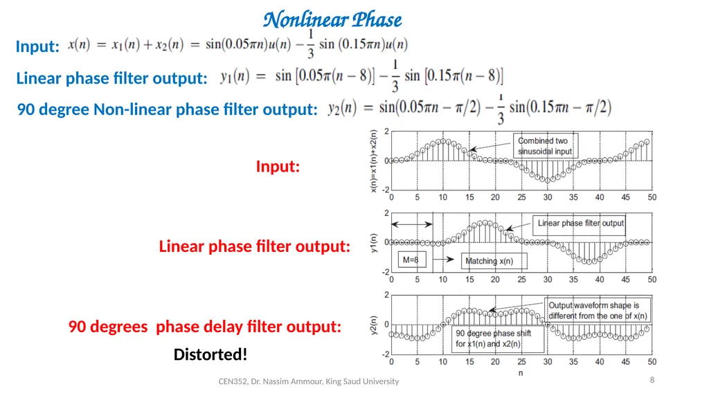
slide8. CEN352, Dr. Nassim Ammour, King Saud University 8 Nonlinear Phase Input: Linear phase filter output: 90 degree Non-linear phase filter output: Input: Linear phase filter output: 90 degrees phase delay filter output: Distorted!<br>
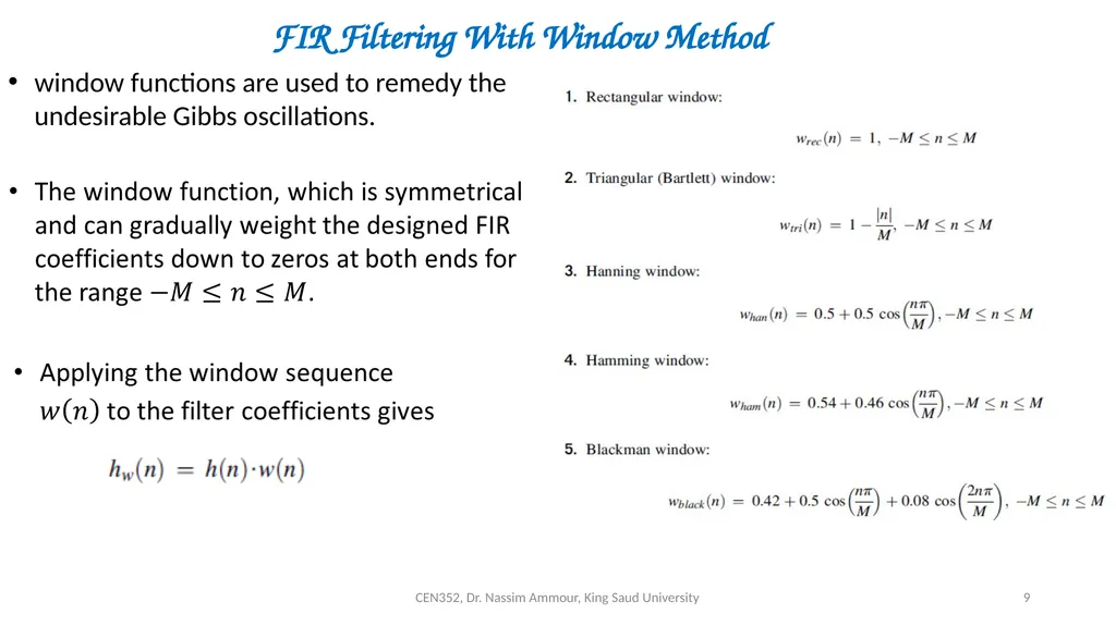
slide9. CEN352, Dr. Nassim Ammour, King Saud University 9 FIR Filtering With Window Method window functions are used to remedy the undesirable Gibbs oscillations.<br>
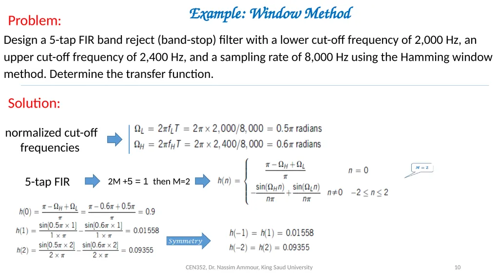
slide10. CEN352, Dr. Nassim Ammour, King Saud University 10 Example: Window Method Design a 5-tap FIR band reject (band-stop) filter with a lower cut-off frequency of 2,000 Hz, an upper cut-off frequency of 2,400 Hz, and a sampling rate of 8,000 Hz using the Hamming window method. Determine the transfer function. Problem: Solution: normalized cut-off frequencies 5-tap FIR 2M + 1 = 5 then M=2<br>
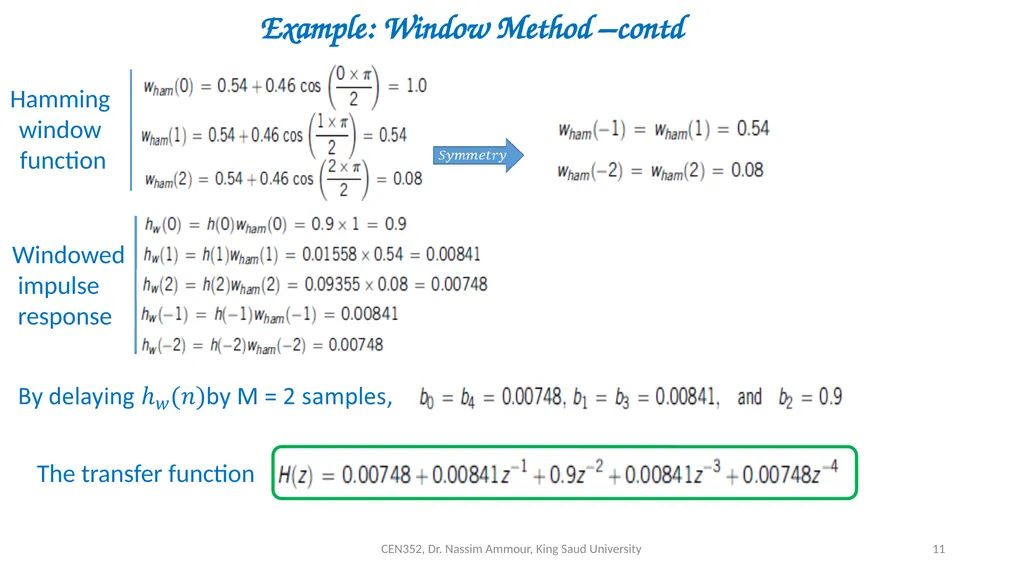
slide11. CEN352, Dr. Nassim Ammour, King Saud University 11 Example: Window Method –contd Hamming
window
function Windowed
impulse
response The transfer function<br>
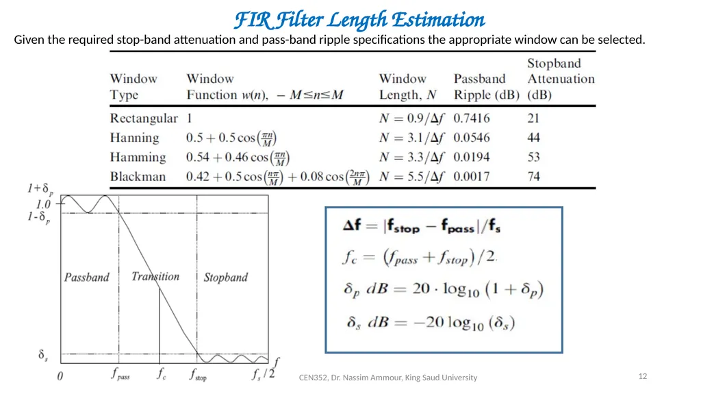
slide12. CEN352, Dr. Nassim Ammour, King Saud University 12 FIR Filter Length Estimation Given the required stop-band attenuation and pass-band ripple specifications the appropriate window can be selected.<br>
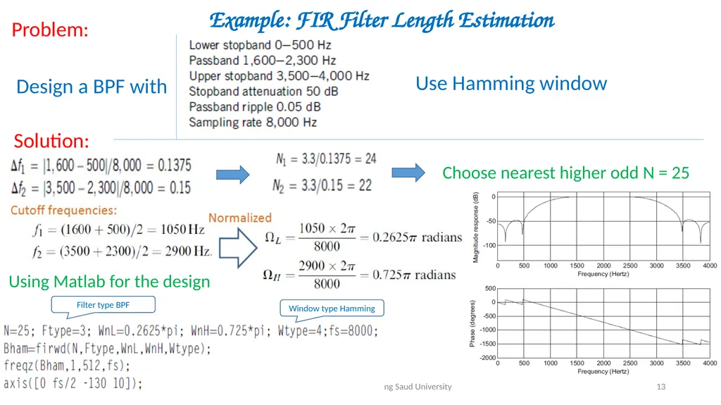
slide13. CEN352, Dr. Nassim Ammour, King Saud University 13 Example: FIR Filter Length Estimation Problem: Solution: Design a BPF with Use Hamming window Choose nearest higher odd N = 25 Using Matlab for the design Window type Hamming Filter type BPF<br>
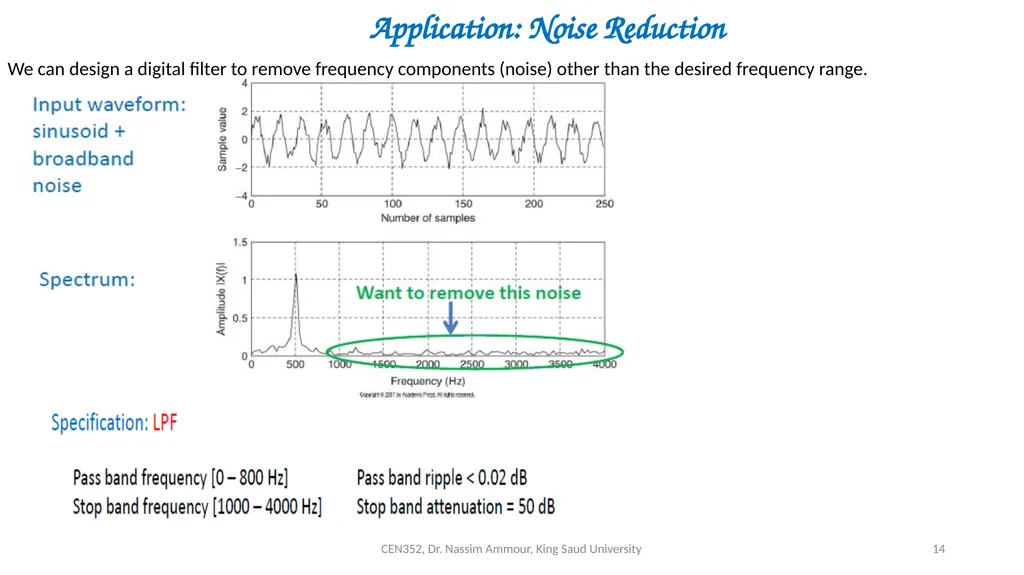
slide14. CEN352, Dr. Nassim Ammour, King Saud University 14 Application: Noise Reduction We can design a digital filter to remove frequency components (noise) other than the desired frequency range.<br>
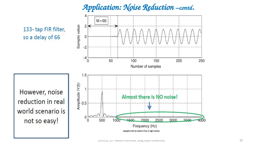
slide15. CEN352, Dr. Nassim Ammour, King Saud University 15 Application: Noise Reduction –contd.<br>
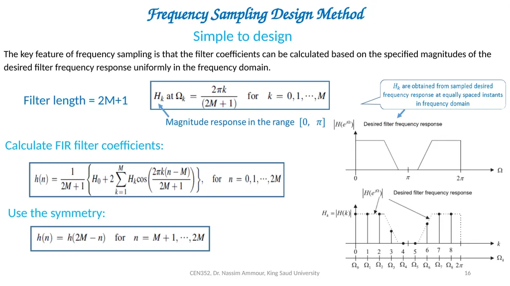
slide16. CEN352, Dr. Nassim Ammour, King Saud University 16 Frequency Sampling Design Method Simple to design Filter length = 2M+1 The key feature of frequency sampling is that the filter coefficients can be calculated based on the specified magnitudes of the desired filter frequency response uniformly in the frequency domain. Calculate FIR filter coefficients: Use the symmetry:<br>
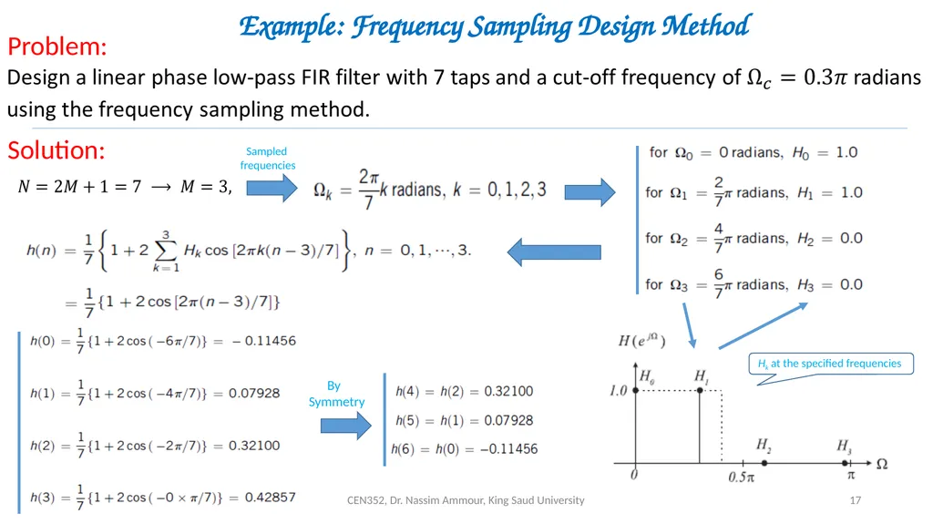
slide17. CEN352, Dr. Nassim Ammour, King Saud University 17 Example: Frequency Sampling Design Method Problem: Solution: Sampled
frequencies Hk at the specified frequencies By
Symmetry<br>
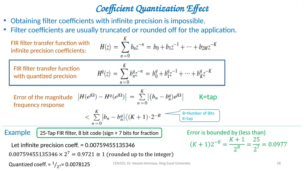
slide18. CEN352, Dr. Nassim Ammour, King Saud University 18 Coefficient Quantization Effect Obtaining filter coefficients with infinite precision is impossible.
Filter coefficients are usually truncated or rounded off for the application. Error of the magnitude frequency response K=tap B=Number of Bits
K=tap Example 25-Tap FIR filter, 8 bit code (sign + 7 bits for fraction Let infinite precision coeff. = 0.00759455135346<br>
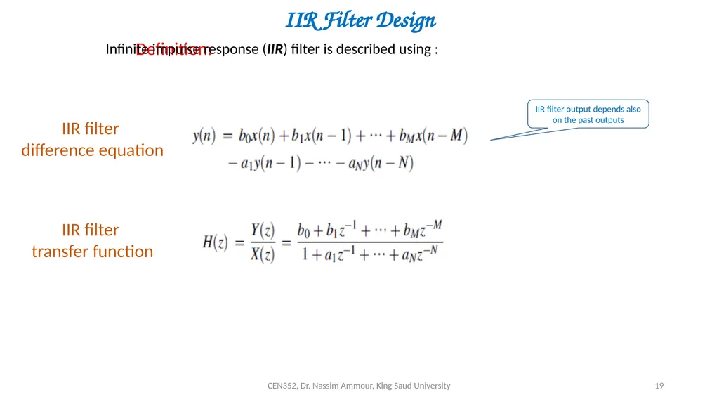
slide19. CEN352, Dr. Nassim Ammour, King Saud University 19 IIR Filter Design Definition: Infinite impulse response (IIR) filter is described using : IIR filter
transfer function IIR filter
difference equation IIR filter output depends also on the past outputs<br>
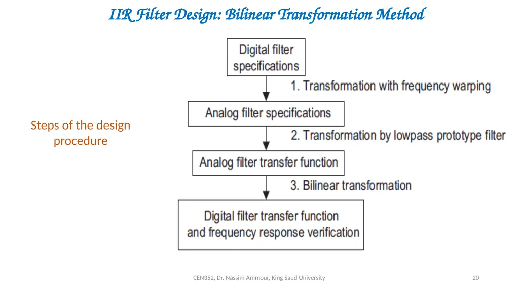
slide20. CEN352, Dr. Nassim Ammour, King Saud University 20 IIR Filter Design: Bilinear Transformation Method Steps of the design procedure<br>
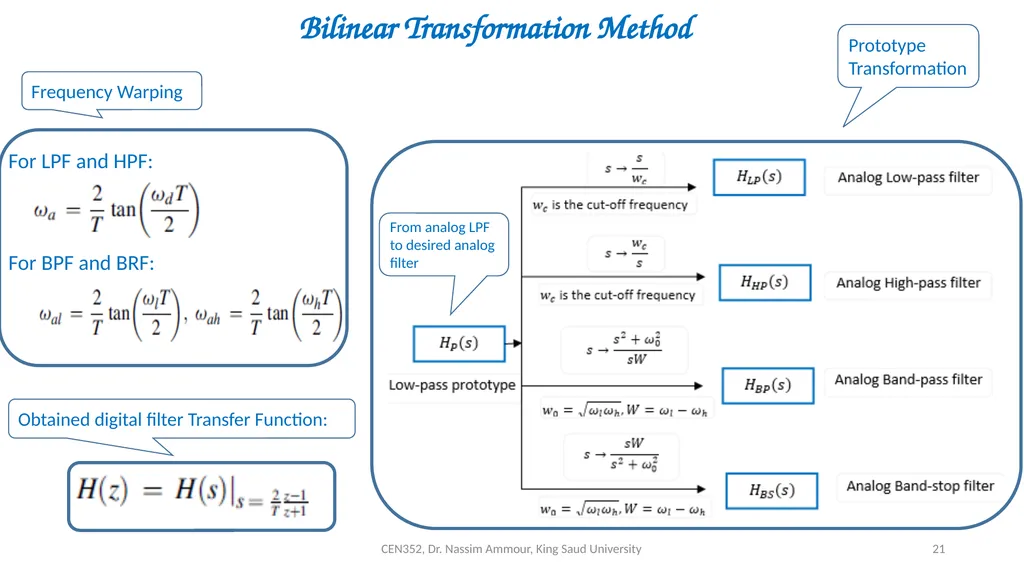
slide21. CEN352, Dr. Nassim Ammour, King Saud University 21 Bilinear Transformation Method For LPF and HPF: For BPF and BRF: Frequency Warping Prototype Transformation Obtained digital filter Transfer Function:<br>
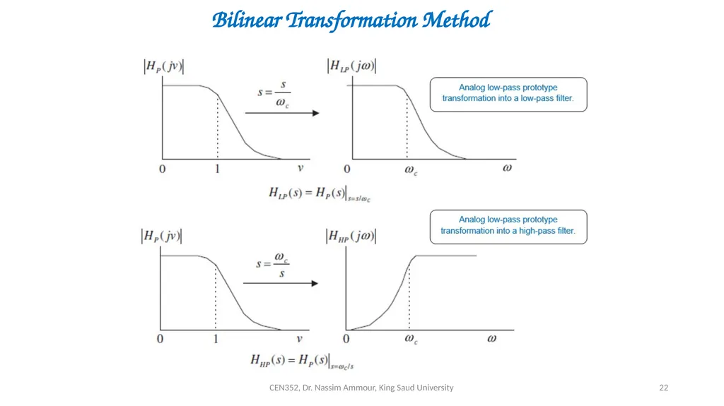
slide22. CEN352, Dr. Nassim Ammour, King Saud University 22 Bilinear Transformation Method<br>
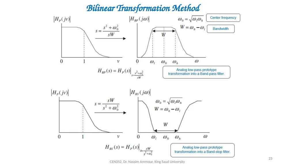
slide23. CEN352, Dr. Nassim Ammour, King Saud University 23 Bilinear Transformation Method<br>
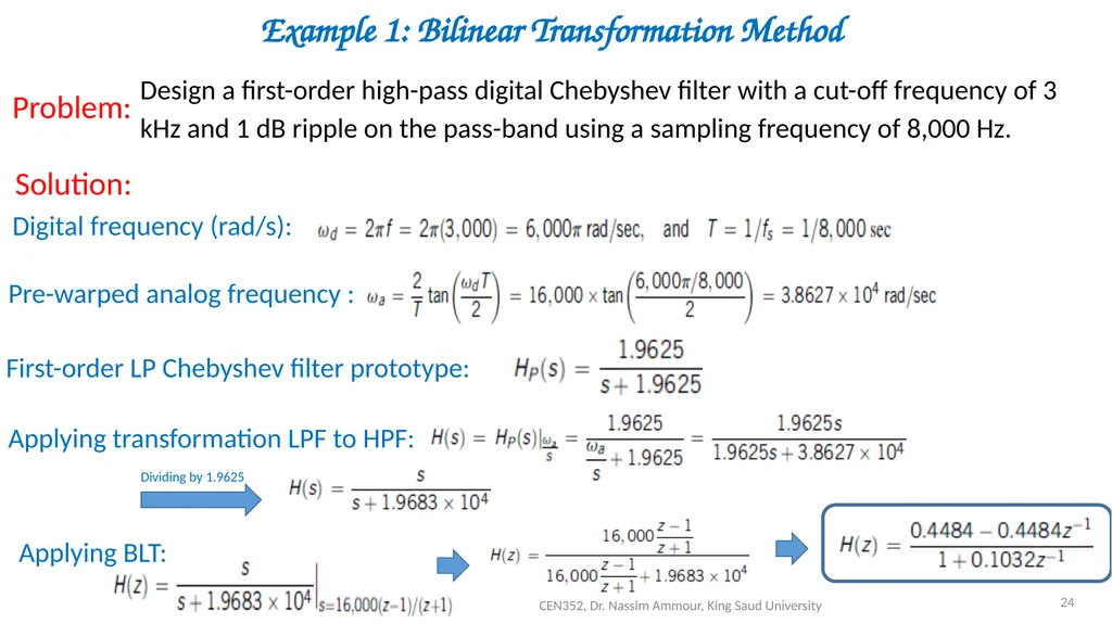
slide24. CEN352, Dr. Nassim Ammour, King Saud University 24 Example 1: Bilinear Transformation Method Design a first-order high-pass digital Chebyshev filter with a cut-off frequency of 3 kHz and 1 dB ripple on the pass-band using a sampling frequency of 8,000 Hz. Problem: Solution: Digital frequency (rad/s): Pre-warped analog frequency : First-order LP Chebyshev filter prototype: Applying transformation LPF to HPF: Dividing by 1.9625 Applying BLT:<br>
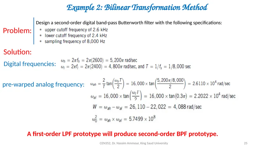
slide25. CEN352, Dr. Nassim Ammour, King Saud University 25 Example 2: Bilinear Transformation Method Problem: Solution: Design a second-order digital band-pass Butterworth filter with the following specifications: Digital frequencies: pre-warped analog frequency: A first-order LPF prototype will produce second-order BPF prototype.<br>
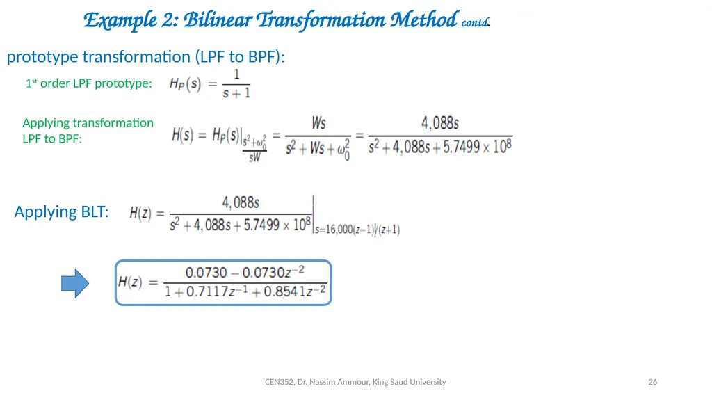
slide26. CEN352, Dr. Nassim Ammour, King Saud University 26 Example 2: Bilinear Transformation Method contd. prototype transformation (LPF to BPF): 1st order LPF prototype: Applying transformation LPF to BPF: Applying BLT:<br>
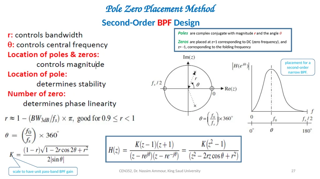
slide27. CEN352, Dr. Nassim Ammour, King Saud University 27 Pole Zero Placement Method Second-Order BPF Design scale to have unit pass-band BPF gain Pole-zero placement for a second-order narrow BPF.<br>
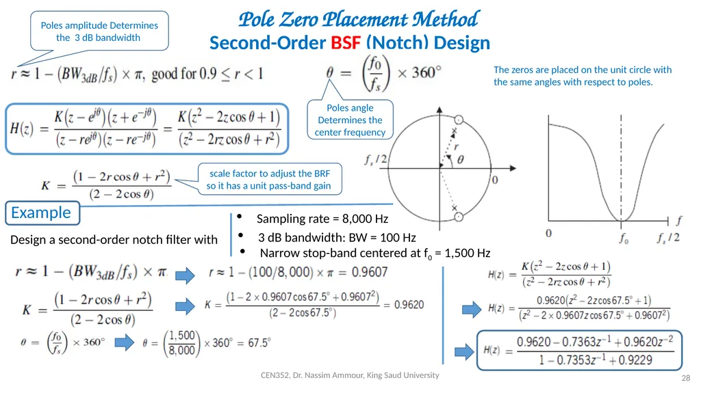
slide28. CEN352, Dr. Nassim Ammour, King Saud University 28 Pole Zero Placement Method Second-Order BSF (Notch) Design The zeros are placed on the unit circle with the same angles with respect to poles. Poles amplitude Determines the 3 dB bandwidth Poles angle Determines the center frequency scale factor to adjust the BRF so it has a unit pass-band gain Example Design a second-order notch filter with Sampling rate = 8,000 Hz 3 dB bandwidth: BW = 100 Hz Narrow stop-band centered at f0 = 1,500 Hz<br>
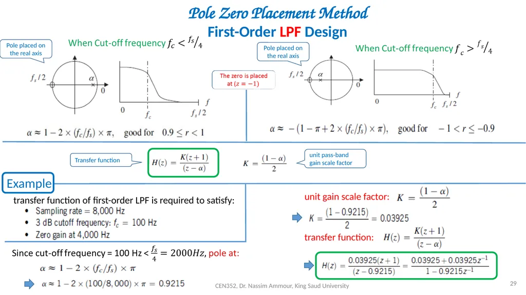
slide29. CEN352, Dr. Nassim Ammour, King Saud University 29 Pole Zero Placement Method
First-Order LPF Design Pole placed on the real axis Pole placed on the real axis Example unit pass-band gain scale factor Transfer function transfer function of first-order LPF is required to satisfy: unit gain scale factor: transfer function:<br>
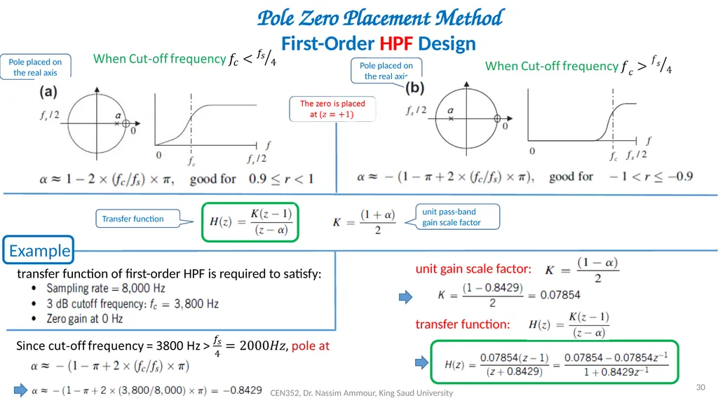
slide30. CEN352, Dr. Nassim Ammour, King Saud University 30 Pole Zero Placement Method
First-Order HPF Design Pole placed on the real axis Pole placed on the real axis Example unit pass-band gain scale factor Transfer function transfer function of first-order HPF is required to satisfy: unit gain scale factor: transfer function:<br>
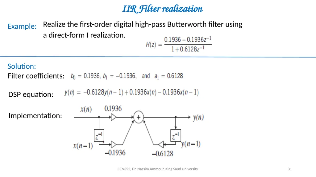
slide31. CEN352, Dr. Nassim Ammour, King Saud University 31 IIR Filter realization Example: Realize the first-order digital high-pass Butterworth filter using a direct-form I realization. Solution: Filter coefficients: DSP equation: Implementation:<br>
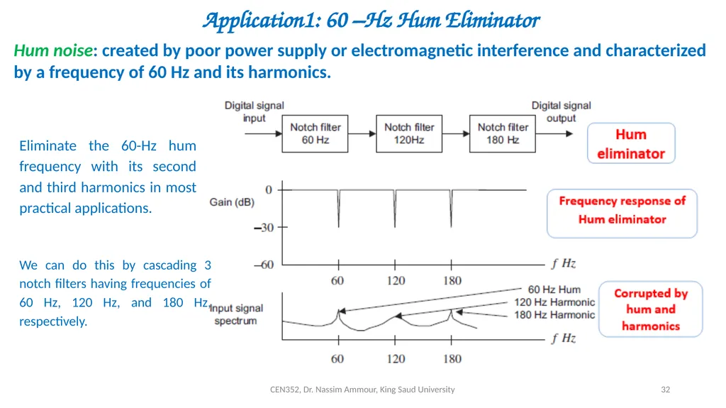
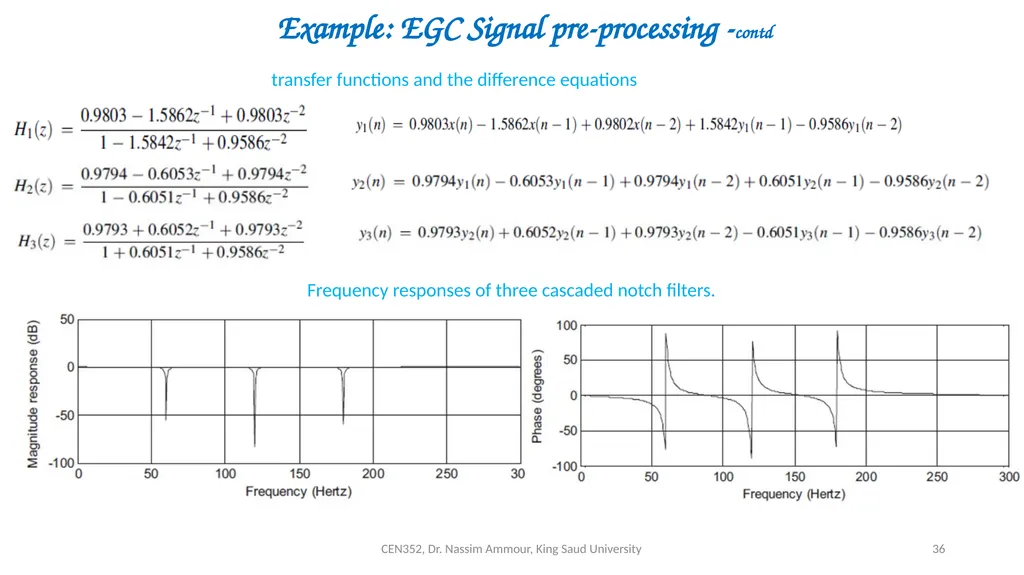
slide32. CEN352, Dr. Nassim Ammour, King Saud University 32 Application1: 60 –Hz Hum Eliminator Hum noise: created by poor power supply or electromagnetic interference and characterized by a frequency of 60 Hz and its harmonics. Eliminate the 60-Hz hum frequency with its second and third harmonics in most practical applications. We can do this by cascading 3 notch filters having frequencies of 60 Hz, 120 Hz, and 180 Hz, respectively.<br>
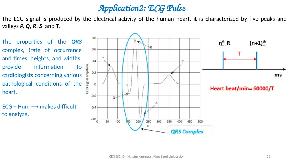
slide33. CEN352, Dr. Nassim Ammour, King Saud University 33 Application2: ECG Pulse The ECG signal is produced by the electrical activity of the human heart, it is characterized by five peaks and valleys P, Q, R, S, and T. The properties of the QRS complex, (rate of occurrence and times, heights, and widths, provide information to cardiologists concerning various pathological conditions of the heart.<br>
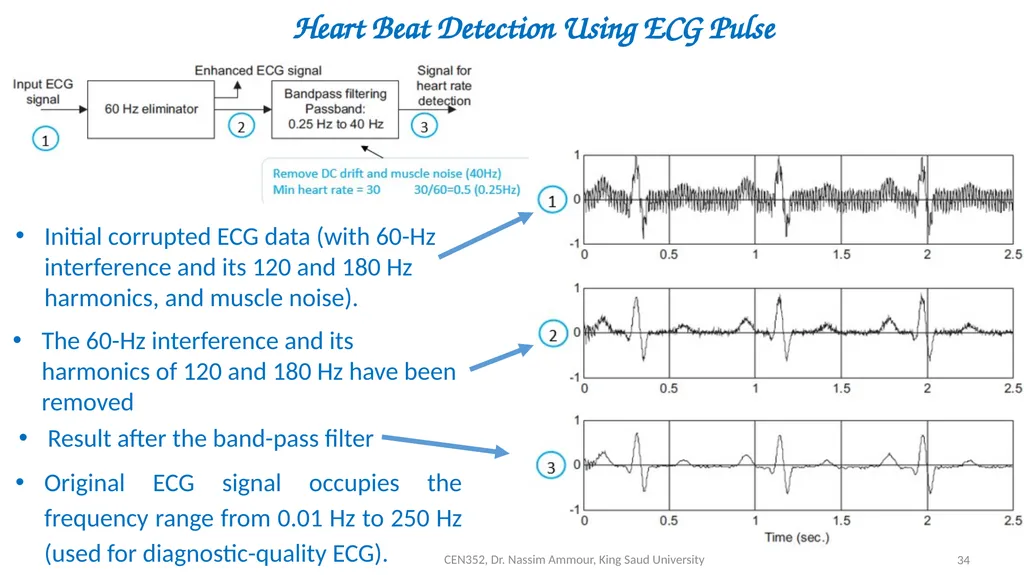
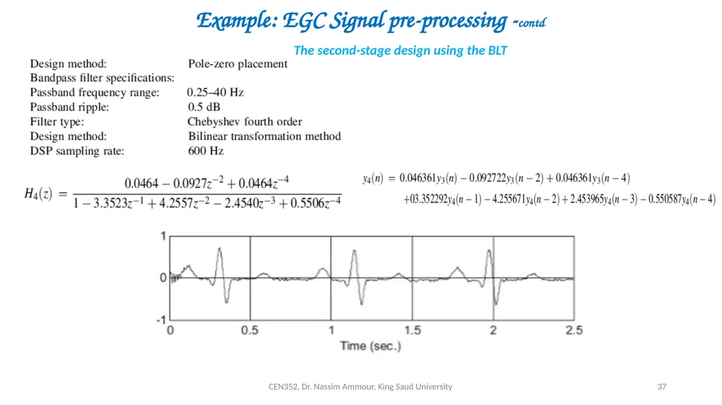
slide34. CEN352, Dr. Nassim Ammour, King Saud University 34 Heart Beat Detection Using ECG Pulse Initial corrupted ECG data (with 60-Hz interference and its 120 and 180 Hz harmonics, and muscle noise). The 60-Hz interference and its harmonics of 120 and 180 Hz have been removed Result after the band-pass filter Original ECG signal occupies the frequency range from 0.01 Hz to 250 Hz (used for diagnostic-quality ECG).<br>
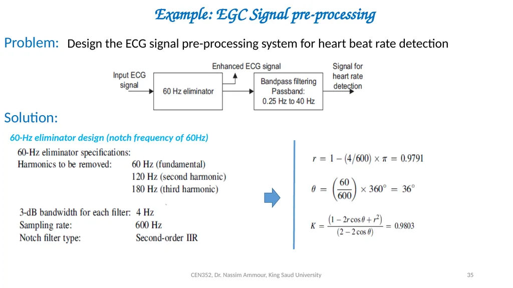
slide35. CEN352, Dr. Nassim Ammour, King Saud University 35 Example: EGC Signal pre-processing Design the ECG signal pre-processing system for heart beat rate detection Problem: Solution: 60-Hz eliminator design (notch frequency of 60Hz)<br>
slide36. CEN352, Dr. Nassim Ammour, King Saud University 36 transfer functions and the difference equations Example: EGC Signal pre-processing -contd Frequency responses of three cascaded notch filters.<br>
slide37. CEN352, Dr. Nassim Ammour, King Saud University 37 Example: EGC Signal pre-processing -contd The second-stage design using the BLT<br>
slide2. CEN352, Dr. Nassim Ammour, King Saud University 2 FIR Filter Design The transfer function of the FIR filter: The difference equation The realization of the FIR filter<br>
slide3. CEN352, Dr. Nassim Ammour, King Saud University 3 Fourier Transform Design Method Frequency response of ideal LPF: Impulse response of ideal LPF: To obtain causal FIR filter, h(n) is delayed by M samples. Where,<br>
slide4. CEN352, Dr. Nassim Ammour, King Saud University 4 Ideal Impulse Responses for Standard FIR Filters<br>
slide5. CEN352, Dr. Nassim Ammour, King Saud University 5 Example Solution FIR Low Pass Filter Design<br>
slide6. CEN352, Dr. Nassim Ammour, King Saud University 6 b. The transfer function: Causal FIR filter coefficients Example - Contd. inverse z-transform c. The magnitude frequency response and phase response Using Euler formula Magnitude and phase frequency
response<br>
slide7. CEN352, Dr. Nassim Ammour, King Saud University 7 Linear Phase If filter has linear phase property (the FIR coefficients are symmetric about the middle coefficient, and the FIR filter order is an odd number), the output will simply be a delayed version of input. Let, 17-tap FIR filter with linear phase property (M=8). M=8 samples delay M=8 samples delay<br>
slide8. CEN352, Dr. Nassim Ammour, King Saud University 8 Nonlinear Phase Input: Linear phase filter output: 90 degree Non-linear phase filter output: Input: Linear phase filter output: 90 degrees phase delay filter output: Distorted!<br>
slide9. CEN352, Dr. Nassim Ammour, King Saud University 9 FIR Filtering With Window Method window functions are used to remedy the undesirable Gibbs oscillations.<br>
slide10. CEN352, Dr. Nassim Ammour, King Saud University 10 Example: Window Method Design a 5-tap FIR band reject (band-stop) filter with a lower cut-off frequency of 2,000 Hz, an upper cut-off frequency of 2,400 Hz, and a sampling rate of 8,000 Hz using the Hamming window method. Determine the transfer function. Problem: Solution: normalized cut-off frequencies 5-tap FIR 2M + 1 = 5 then M=2<br>
slide11. CEN352, Dr. Nassim Ammour, King Saud University 11 Example: Window Method –contd Hamming
window
function Windowed
impulse
response The transfer function<br>
slide12. CEN352, Dr. Nassim Ammour, King Saud University 12 FIR Filter Length Estimation Given the required stop-band attenuation and pass-band ripple specifications the appropriate window can be selected.<br>
slide13. CEN352, Dr. Nassim Ammour, King Saud University 13 Example: FIR Filter Length Estimation Problem: Solution: Design a BPF with Use Hamming window Choose nearest higher odd N = 25 Using Matlab for the design Window type Hamming Filter type BPF<br>
slide14. CEN352, Dr. Nassim Ammour, King Saud University 14 Application: Noise Reduction We can design a digital filter to remove frequency components (noise) other than the desired frequency range.<br>
slide15. CEN352, Dr. Nassim Ammour, King Saud University 15 Application: Noise Reduction –contd.<br>
slide16. CEN352, Dr. Nassim Ammour, King Saud University 16 Frequency Sampling Design Method Simple to design Filter length = 2M+1 The key feature of frequency sampling is that the filter coefficients can be calculated based on the specified magnitudes of the desired filter frequency response uniformly in the frequency domain. Calculate FIR filter coefficients: Use the symmetry:<br>
slide17. CEN352, Dr. Nassim Ammour, King Saud University 17 Example: Frequency Sampling Design Method Problem: Solution: Sampled
frequencies Hk at the specified frequencies By
Symmetry<br>
slide18. CEN352, Dr. Nassim Ammour, King Saud University 18 Coefficient Quantization Effect Obtaining filter coefficients with infinite precision is impossible.
Filter coefficients are usually truncated or rounded off for the application. Error of the magnitude frequency response K=tap B=Number of Bits
K=tap Example 25-Tap FIR filter, 8 bit code (sign + 7 bits for fraction Let infinite precision coeff. = 0.00759455135346<br>
slide19. CEN352, Dr. Nassim Ammour, King Saud University 19 IIR Filter Design Definition: Infinite impulse response (IIR) filter is described using : IIR filter
transfer function IIR filter
difference equation IIR filter output depends also on the past outputs<br>
slide20. CEN352, Dr. Nassim Ammour, King Saud University 20 IIR Filter Design: Bilinear Transformation Method Steps of the design procedure<br>
slide21. CEN352, Dr. Nassim Ammour, King Saud University 21 Bilinear Transformation Method For LPF and HPF: For BPF and BRF: Frequency Warping Prototype Transformation Obtained digital filter Transfer Function:<br>
slide22. CEN352, Dr. Nassim Ammour, King Saud University 22 Bilinear Transformation Method<br>
slide23. CEN352, Dr. Nassim Ammour, King Saud University 23 Bilinear Transformation Method<br>
slide24. CEN352, Dr. Nassim Ammour, King Saud University 24 Example 1: Bilinear Transformation Method Design a first-order high-pass digital Chebyshev filter with a cut-off frequency of 3 kHz and 1 dB ripple on the pass-band using a sampling frequency of 8,000 Hz. Problem: Solution: Digital frequency (rad/s): Pre-warped analog frequency : First-order LP Chebyshev filter prototype: Applying transformation LPF to HPF: Dividing by 1.9625 Applying BLT:<br>
slide25. CEN352, Dr. Nassim Ammour, King Saud University 25 Example 2: Bilinear Transformation Method Problem: Solution: Design a second-order digital band-pass Butterworth filter with the following specifications: Digital frequencies: pre-warped analog frequency: A first-order LPF prototype will produce second-order BPF prototype.<br>
slide26. CEN352, Dr. Nassim Ammour, King Saud University 26 Example 2: Bilinear Transformation Method contd. prototype transformation (LPF to BPF): 1st order LPF prototype: Applying transformation LPF to BPF: Applying BLT:<br>
slide27. CEN352, Dr. Nassim Ammour, King Saud University 27 Pole Zero Placement Method Second-Order BPF Design scale to have unit pass-band BPF gain Pole-zero placement for a second-order narrow BPF.<br>
slide28. CEN352, Dr. Nassim Ammour, King Saud University 28 Pole Zero Placement Method Second-Order BSF (Notch) Design The zeros are placed on the unit circle with the same angles with respect to poles. Poles amplitude Determines the 3 dB bandwidth Poles angle Determines the center frequency scale factor to adjust the BRF so it has a unit pass-band gain Example Design a second-order notch filter with Sampling rate = 8,000 Hz 3 dB bandwidth: BW = 100 Hz Narrow stop-band centered at f0 = 1,500 Hz<br>
slide29. CEN352, Dr. Nassim Ammour, King Saud University 29 Pole Zero Placement Method
First-Order LPF Design Pole placed on the real axis Pole placed on the real axis Example unit pass-band gain scale factor Transfer function transfer function of first-order LPF is required to satisfy: unit gain scale factor: transfer function:<br>
slide30. CEN352, Dr. Nassim Ammour, King Saud University 30 Pole Zero Placement Method
First-Order HPF Design Pole placed on the real axis Pole placed on the real axis Example unit pass-band gain scale factor Transfer function transfer function of first-order HPF is required to satisfy: unit gain scale factor: transfer function:<br>
slide31. CEN352, Dr. Nassim Ammour, King Saud University 31 IIR Filter realization Example: Realize the first-order digital high-pass Butterworth filter using a direct-form I realization. Solution: Filter coefficients: DSP equation: Implementation:<br>
slide32. CEN352, Dr. Nassim Ammour, King Saud University 32 Application1: 60 –Hz Hum Eliminator Hum noise: created by poor power supply or electromagnetic interference and characterized by a frequency of 60 Hz and its harmonics. Eliminate the 60-Hz hum frequency with its second and third harmonics in most practical applications. We can do this by cascading 3 notch filters having frequencies of 60 Hz, 120 Hz, and 180 Hz, respectively.<br>
slide33. CEN352, Dr. Nassim Ammour, King Saud University 33 Application2: ECG Pulse The ECG signal is produced by the electrical activity of the human heart, it is characterized by five peaks and valleys P, Q, R, S, and T. The properties of the QRS complex, (rate of occurrence and times, heights, and widths, provide information to cardiologists concerning various pathological conditions of the heart.<br>
slide34. CEN352, Dr. Nassim Ammour, King Saud University 34 Heart Beat Detection Using ECG Pulse Initial corrupted ECG data (with 60-Hz interference and its 120 and 180 Hz harmonics, and muscle noise). The 60-Hz interference and its harmonics of 120 and 180 Hz have been removed Result after the band-pass filter Original ECG signal occupies the frequency range from 0.01 Hz to 250 Hz (used for diagnostic-quality ECG).<br>
slide35. CEN352, Dr. Nassim Ammour, King Saud University 35 Example: EGC Signal pre-processing Design the ECG signal pre-processing system for heart beat rate detection Problem: Solution: 60-Hz eliminator design (notch frequency of 60Hz)<br>
slide36. CEN352, Dr. Nassim Ammour, King Saud University 36 transfer functions and the difference equations Example: EGC Signal pre-processing -contd Frequency responses of three cascaded notch filters.<br>
slide37. CEN352, Dr. Nassim Ammour, King Saud University 37 Example: EGC Signal pre-processing -contd The second-stage design using the BLT<br>