ENCODER and DECODER Application of Combinational Logic circuit Encoding and Decoding : When connecting a logic circuit with the outside world, incoming information from a keyboard or other input device must be changed (encoded) into an
"ENCODER and DECODER Application of Combinational" is the property of its rightful owner. Permission is granted to
download and print the materials on this website for personal, non-commercial use only, and to display it
on your personal computer provided you do not modify the materials and that you retain all copyright
notices contained in the materials. By downloading content from our website, you accept the terms of this
agreement.
Presentation Transcript
01
ENCODER and DECODER<br>
02
Application of Combinational Logic circuit Encoding and Decoding :
When connecting a logic circuit with the outside world, incoming information from a keyboard or other input device must be changed (encoded) into an appropriate binary form.
Also before binary data produced by the digital system can be used by an output device, such as a display, it must be decoded into a form that can be used by the display.
Encoders and decoders used for such jobs are also combinational logic circuits<br>
03
Encoder For example text may be represented by an ASCII code (American standard Code for Information Interchange), in which each letter, number or symbol is represented by a 7-bit binary code.
Decimal numbers in a calculator may be sent to a numeric display using BCD (Binary Coded Decimal).
the word ‘code’ appears in each of these titles, and a binary code differs from normal binary because it is arranged in a particular way to suit a given purpose.<br>
04
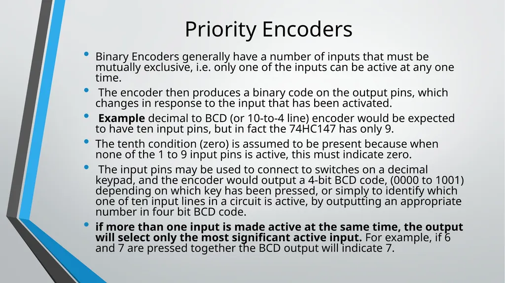
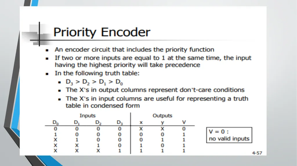
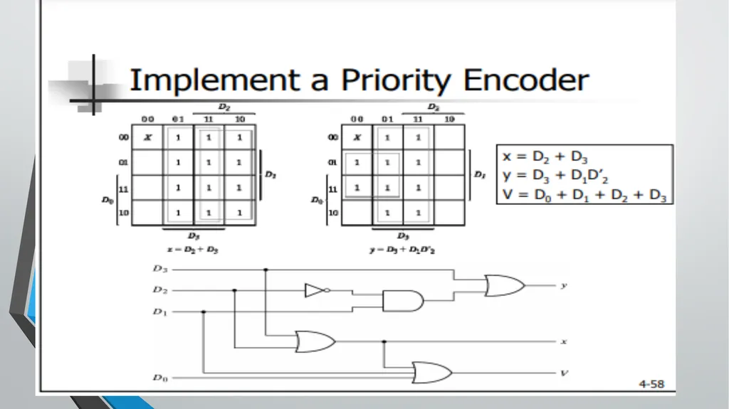
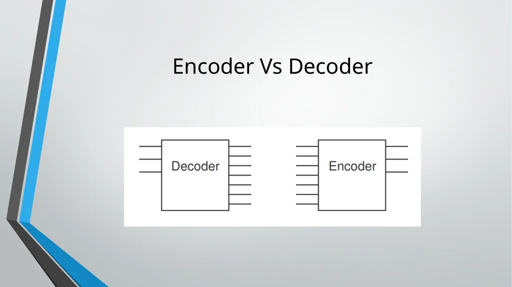
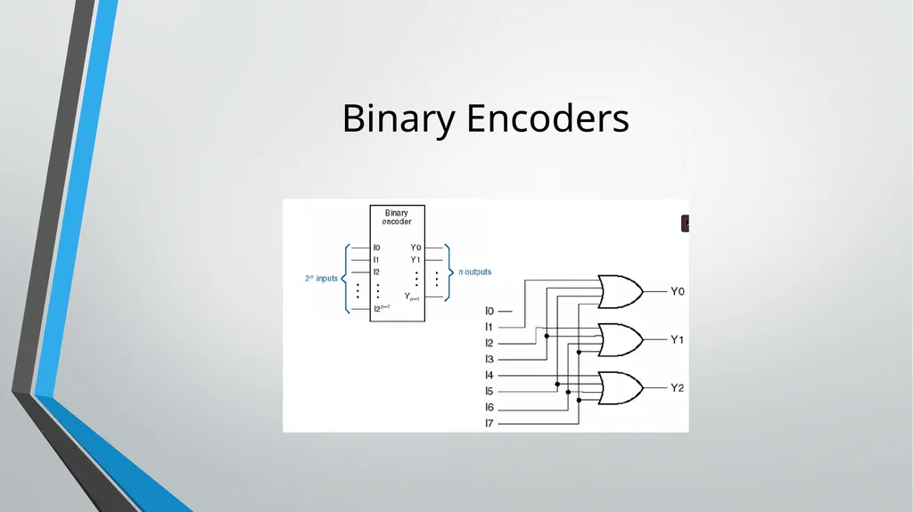
Priority Encoders Binary Encoders generally have a number of inputs that must be mutually exclusive, i.e. only one of the inputs can be active at any one time.
The encoder then produces a binary code on the output pins, which changes in response to the input that has been activated.
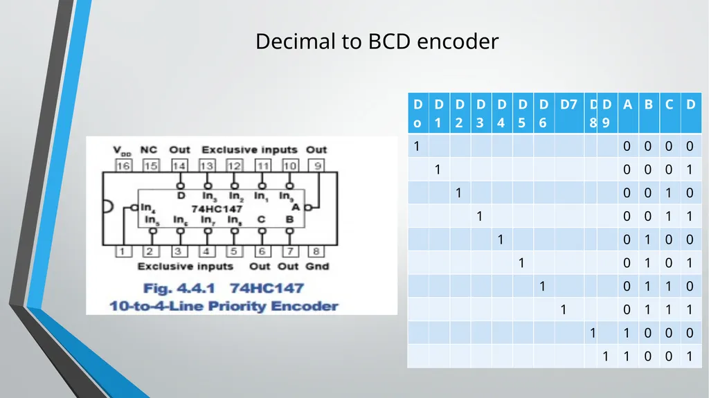
Example decimal to BCD (or 10-to-4 line) encoder would be expected to have ten input pins, but in fact the 74HC147 has only 9.
The tenth condition (zero) is assumed to be present because when none of the 1 to 9 input pins is active, this must indicate zero.
The input pins may be used to connect to switches on a decimal keypad, and the encoder would output a 4-bit BCD code, (0000 to 1001) depending on which key has been pressed, or simply to identify which one of ten input lines in a circuit is active, by outputting an appropriate number in four bit BCD code.
if more than one input is made active at the same time, the output will select only the most significant active input. For example, if 6 and 7 are pressed together the BCD output will indicate 7.<br>
05
Decimal to BCD encoder<br>
06
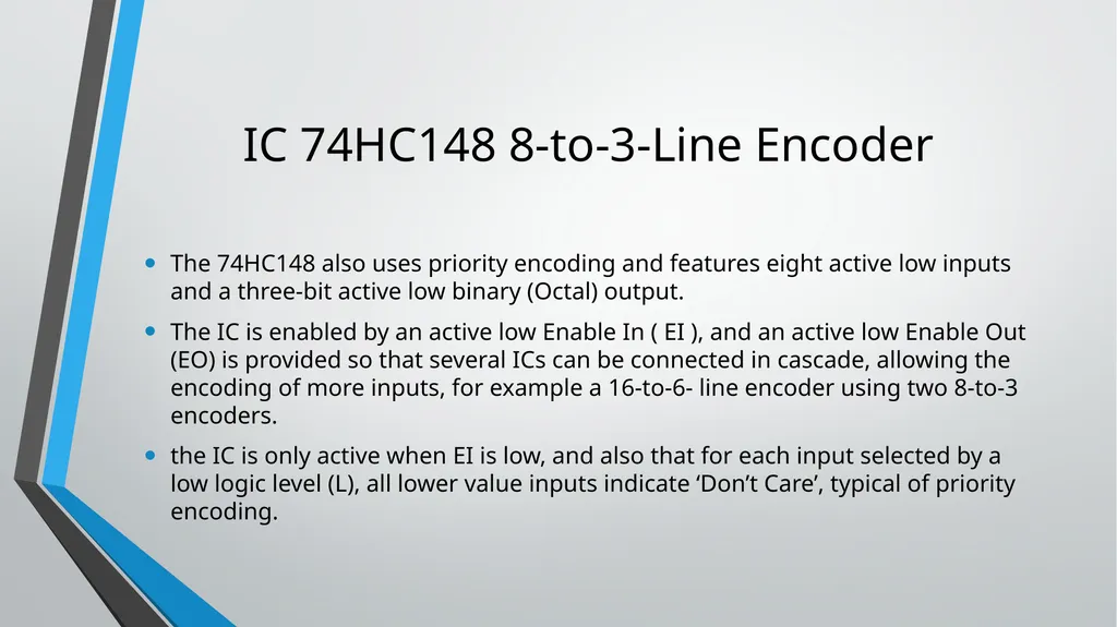
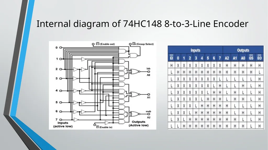
IC 74HC148 8-to-3-Line Encoder The 74HC148 also uses priority encoding and features eight active low inputs and a three-bit active low binary (Octal) output.
The IC is enabled by an active low Enable In ( EI ), and an active low Enable Out (EO) is provided so that several ICs can be connected in cascade, allowing the encoding of more inputs, for example a 16-to-6- line encoder using two 8-to-3 encoders.
the IC is only active when EI is low, and also that for each input selected by a low logic level (L), all lower value inputs indicate ‘Don’t Care’, typical of priority encoding.<br>
07
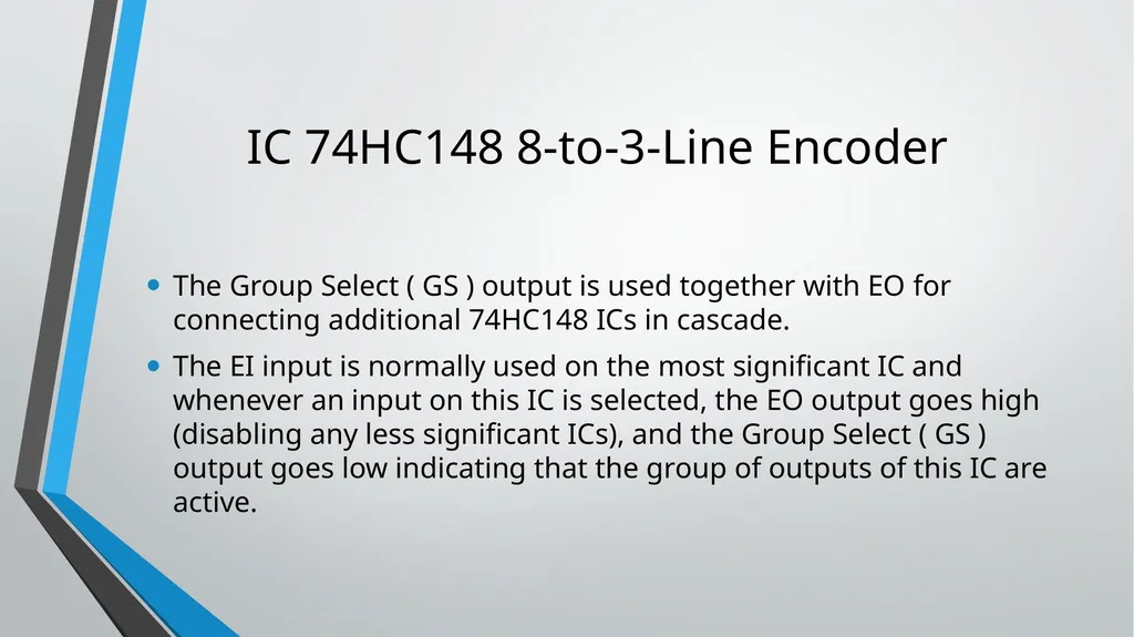
IC 74HC148 8-to-3-Line Encoder The Group Select ( GS ) output is used together with EO for connecting additional 74HC148 ICs in cascade.
The EI input is normally used on the most significant IC and whenever an input on this IC is selected, the EO output goes high (disabling any less significant ICs), and the Group Select ( GS ) output goes low indicating that the group of outputs of this IC are active.<br>
08
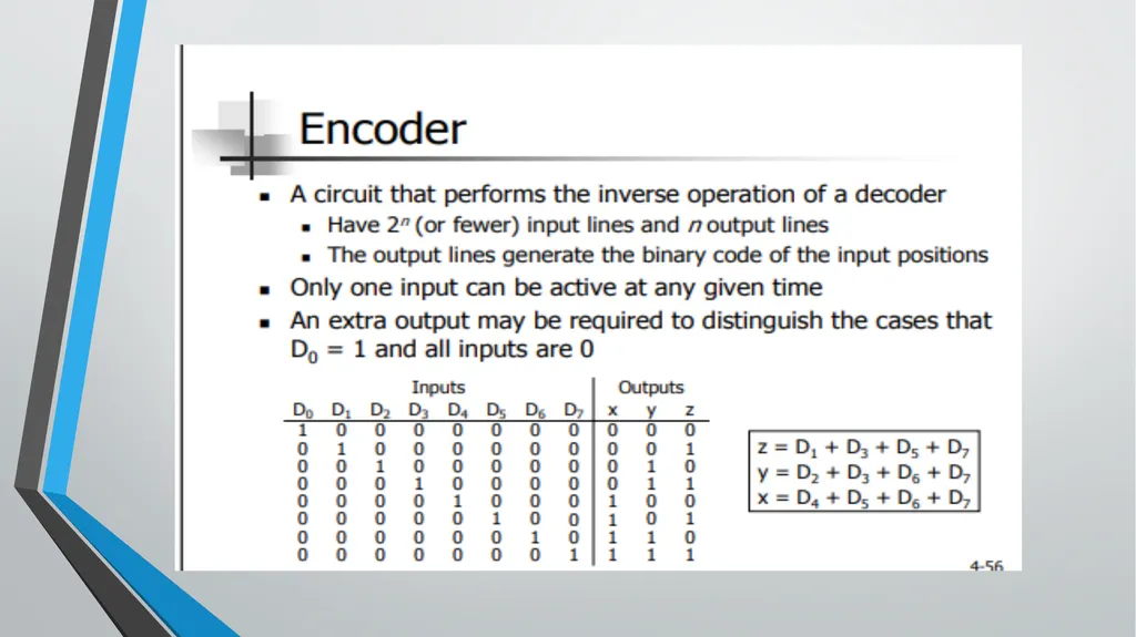
Internal diagram of 74HC148 8-to-3-Line Encoder<br>
09
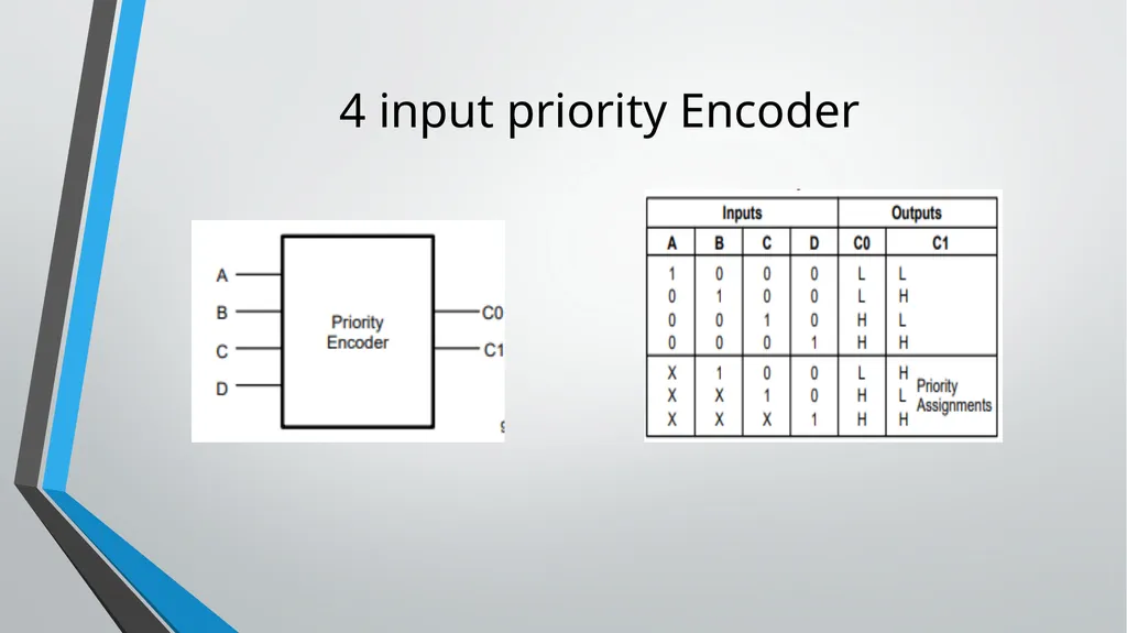
4 input priority Encoder<br>
10
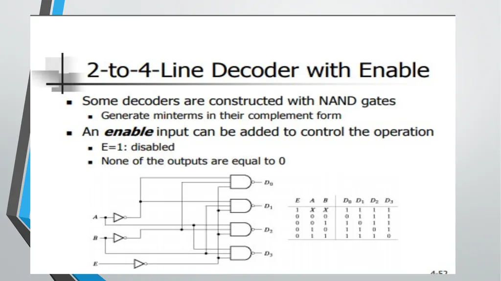
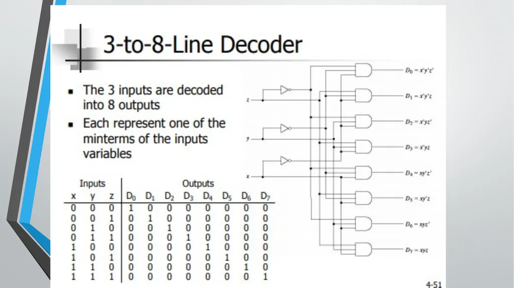
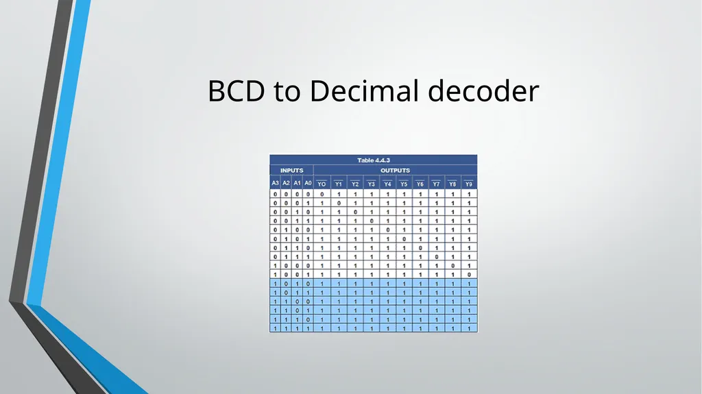
Decoder A circuit that coverts binary information from n input lines to a maximum of 2^n unique output lines
May have fewer than 2^n outputs
A n-to-m-line decoder (m ≤ 2^n): Generate the m minterms of n input variables
For each possible input combination, there is only one output that is equal to 1
The output whose value is equal to 1 represents the minterm equivalent of the binary number presently available in the input lines<br>