Engineering Graphics I Unit-1 Projections of a
Description: Engineering Graphics I Unit-1 Projections of a Point Line By, Prof. Priyanka Narwade Learning objectives: Projections of a Point To Study concept of Principle Planes To Understand theory of Projections Analysis of a point in various
Related Topics
Download Presentation
"Engineering Graphics I Unit-1 Projections of a" is the property of its rightful owner. Permission is granted to download and print the materials on this website for personal, non-commercial use only, and to display it on your personal computer provided you do not modify the materials and that you retain all copyright notices contained in the materials. By downloading content from our website, you accept the terms of this agreement.
Presentation Transcript
slide1. Engineering Graphics IUnit-1Projections of a Point & Line By,
Prof. Priyanka Narwade<br>
slide2. Learning objectives: Projections of a Point To Study concept of Principle Planes
To Understand theory of Projections
Analysis of a point in various quadrants
Analysis of a point in 1st quadrant, its different cases
Theory of projections by auxiliary plane method: AVP & AIP 2<br>
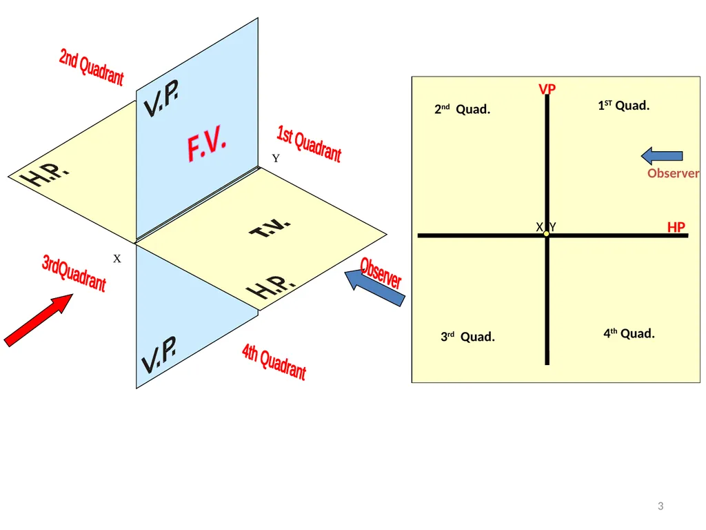
slide3. X Y 1st Quadrant 2nd Quadrant 3rdQuadrant 4th Quadrant F.V. 1ST Quad. 2nd Quad. 3rd Quad. 4th Quad. X Y Observer VP HP Observer 3<br>
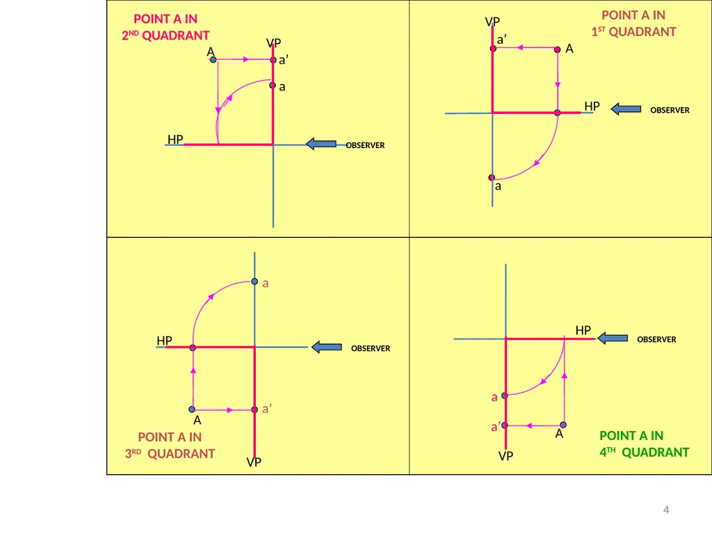
slide4. a’ a A POINT A IN
1ST QUADRANT POINT A IN
2ND QUADRANT a’ a A a a’ POINT A IN
3RD QUADRANT A a a’ POINT A IN
4TH QUADRANT A 4<br>
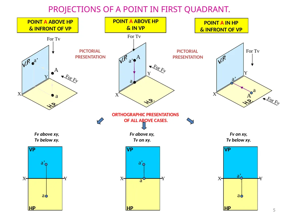
slide5. A a a’ A a a’ A a a’ X Y PROJECTIONS OF A POINT IN FIRST QUADRANT. PICTORIAL
PRESENTATION PICTORIAL
PRESENTATION Fv above xy,
Tv below xy. Fv above xy,
Tv on xy. Fv on xy,
Tv below xy. 5<br>
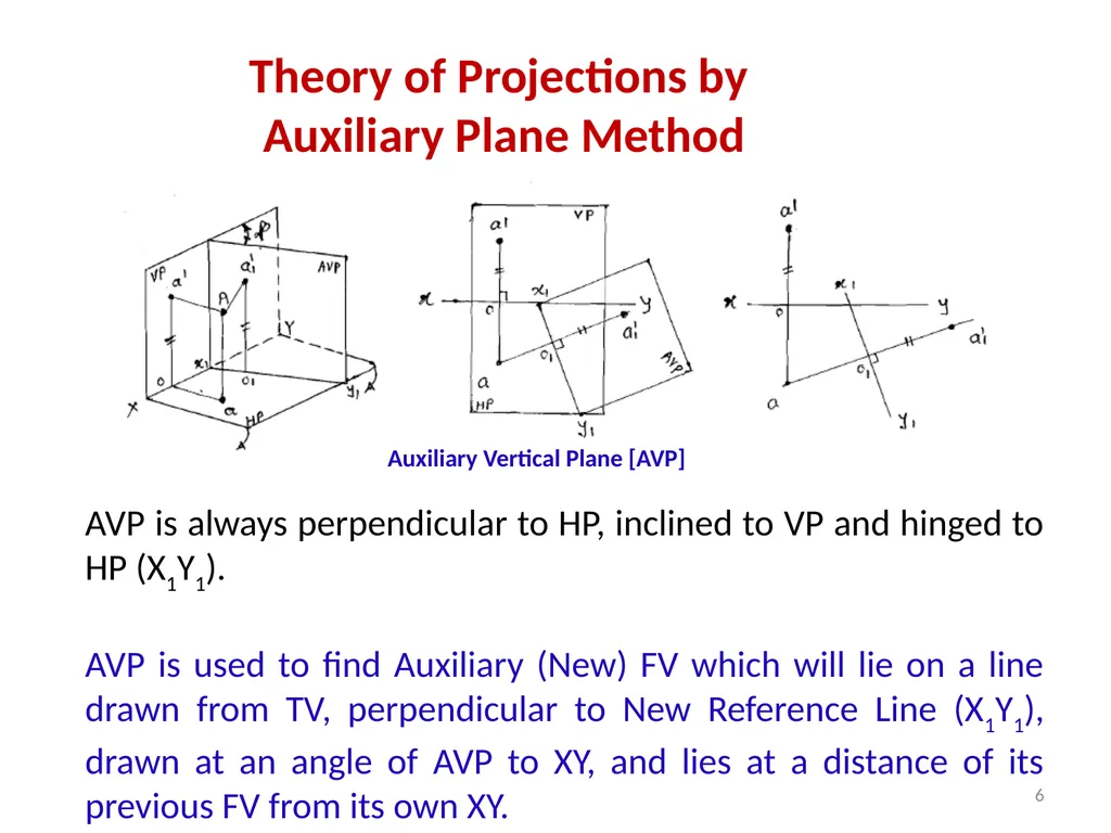
slide6. Theory of Projections by Auxiliary Plane Method Auxiliary Vertical Plane [AVP] AVP is always perpendicular to HP, inclined to VP and hinged to HP (X1Y1).
AVP is used to find Auxiliary (New) FV which will lie on a line drawn from TV, perpendicular to New Reference Line (X1Y1), drawn at an angle of AVP to XY, and lies at a distance of its previous FV from its own XY. 6<br>
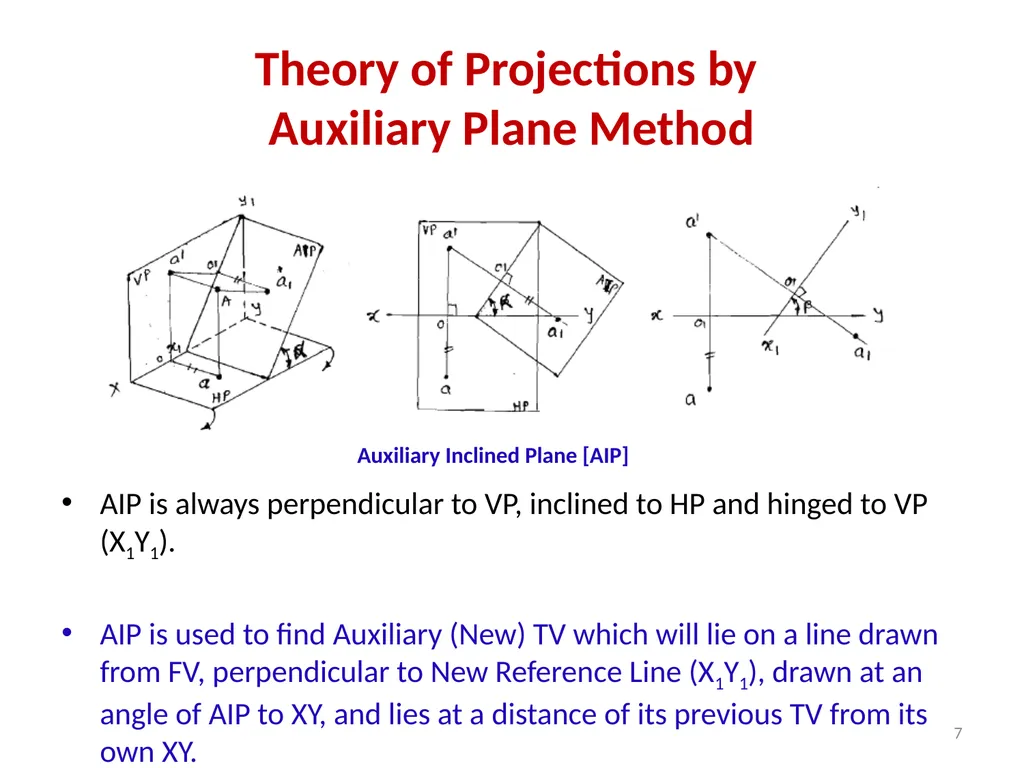
slide7. Theory of Projections by Auxiliary Plane Method AIP is always perpendicular to VP, inclined to HP and hinged to VP (X1Y1).
AIP is used to find Auxiliary (New) TV which will lie on a line drawn from FV, perpendicular to New Reference Line (X1Y1), drawn at an angle of AIP to XY, and lies at a distance of its previous TV from its own XY. Auxiliary Inclined Plane [AIP] 7<br>
slide8. Learning objectives:Projections of a Line To study the Concept of Line
To understand fundamentals of projections of a line
Analysis of a line in 1st quadrant, different cases
Traces of a line: HT & VT
Summarization of concepts & observations of a oblique line 8<br>
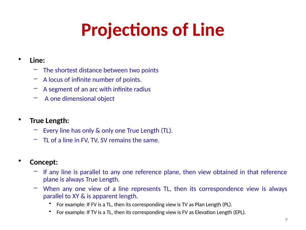
slide9. Projections of Line Line:
The shortest distance between two points
A locus of infinite number of points.
A segment of an arc with infinite radius
A one dimensional object
True Length:
Every line has only & only one True Length (TL).
TL of a line in FV, TV, SV remains the same.
Concept:
If any line is parallel to any one reference plane, then view obtained in that reference plane is always True Length.
When any one view of a line represents TL, then its correspondence view is always parallel to XY & is apparent length.
For example: If FV is a TL, then its corresponding view is TV as Plan Length (PL).
For example: If TV is a TL, then its corresponding view is FV as Elevation Length (EPL). 9<br>
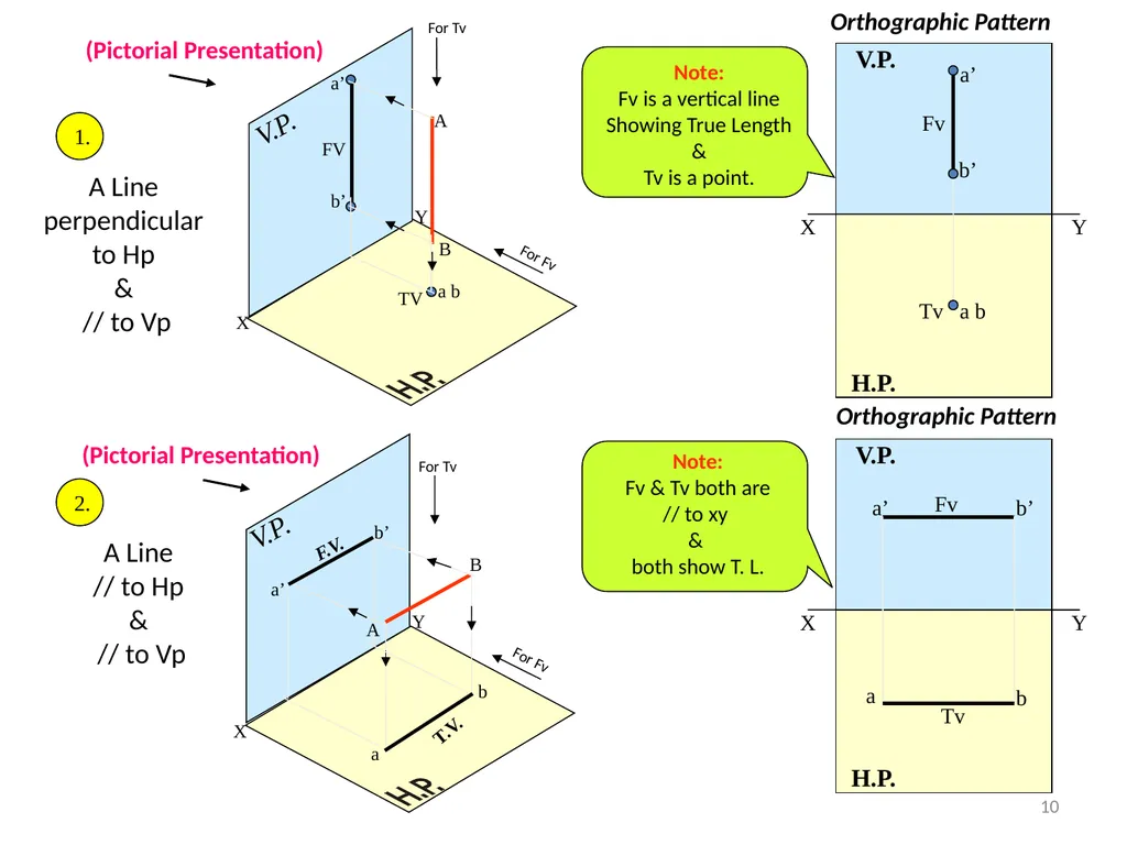
slide10. F.V. T.V. a b TV FV For Fv For Tv For Tv For Fv 1. 2. A Line
perpendicular
to Hp
&
// to Vp A Line
// to Hp
&
// to Vp Orthographic Pattern Orthographic Pattern 10<br>
slide11. A Line inclined to Hp
and
parallel to Vp
(Pictorial presentation) A Line inclined to Vp
and
parallel to Hp
(Pictorial presentation) Ø F.V. T.V. 3. 4. Orthographic Projections 11<br>
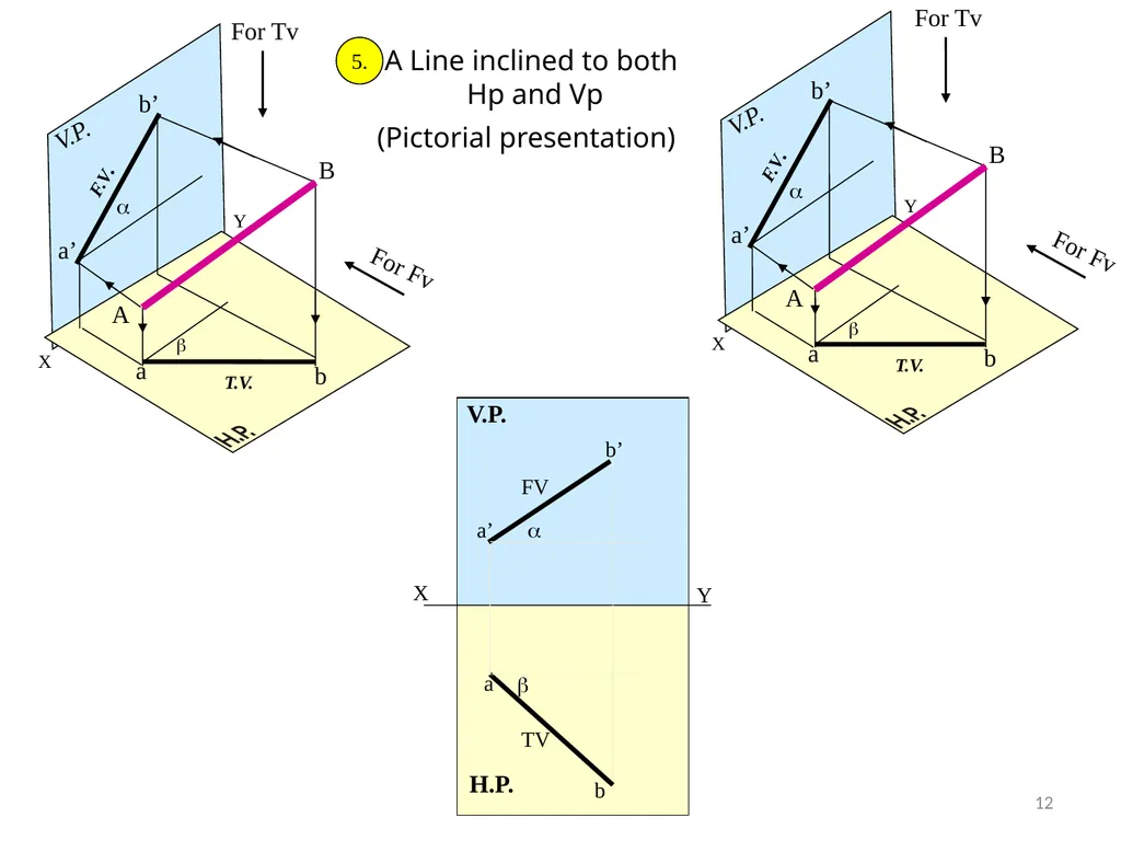
slide12. A Line inclined to both
Hp and Vp
(Pictorial presentation) 5. 12<br>
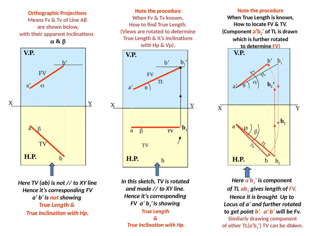
slide13. b1 b1’ TL Here TV (ab) is not // to XY line
Hence it’s corresponding FV
a’ b’ is not showing
True Length &
True Inclination with Hp. In this sketch, TV is rotated
and made // to XY line.
Hence it’s corresponding
FV a’ b1’ Is showing
True Length
&
True Inclination with Hp. Note the procedure
When Fv & Tv known,
How to find True Length.
(Views are rotated to determine
True Length & it’s inclinations
with Hp & Vp). Note the procedure
When True Length is known,
How to locate FV & TV.
(Component a’b2’ of TL is drawn
which is further rotated
to determine FV) b’ TL Fv Orthographic Projections
Means Fv & Tv of Line AB
are shown below,
with their apparent Inclinations
& Here a’b1’ is component
of TL ab1 gives length of FV.
Hence it is brought Up to
Locus of a’ and further rotated
to get point b’. a’ b’ will be Fv.
Similarly drawing component
of other TL(a’b1‘) TV can be drawn. b1 b2’ 13<br>
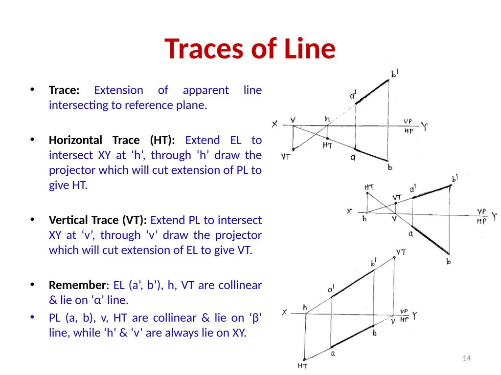
slide14. Traces of Line Trace: Extension of apparent line intersecting to reference plane.
Horizontal Trace (HT): Extend EL to intersect XY at ‘h’, through ‘h’ draw the projector which will cut extension of PL to give HT.
Vertical Trace (VT): Extend PL to intersect XY at ‘v’, through ‘v’ draw the projector which will cut extension of EL to give VT.
Remember: EL (a’, b’), h, VT are collinear & lie on ‘α’ line.
PL (a, b), v, HT are collinear & lie on ‘β’ line, while ‘h’ & ‘v’ are always lie on XY. 14<br>
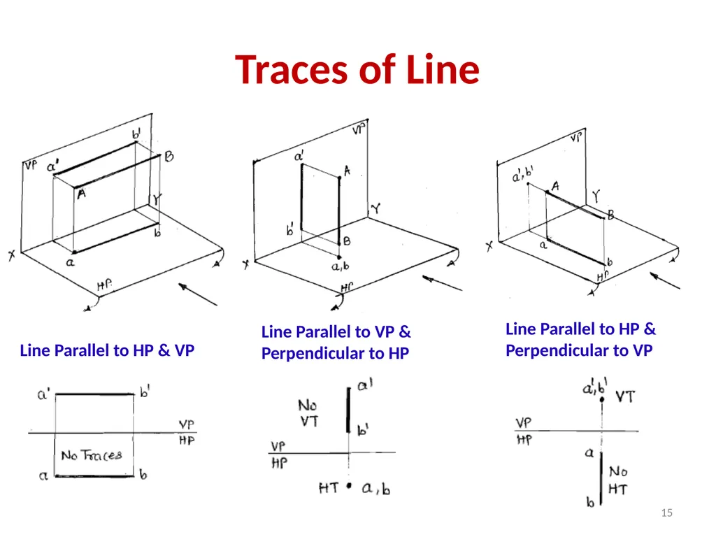
slide15. Traces of Line Line Parallel to HP & VP Line Parallel to VP &
Perpendicular to HP Line Parallel to HP &
Perpendicular to VP 15<br>
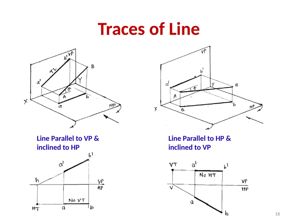
slide16. Traces of Line Line Parallel to VP &
inclined to HP Line Parallel to HP &
inclined to VP 16<br>
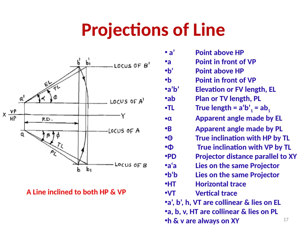
slide17. Projections of Line A Line inclined to both HP & VP a’ Point above HP
a Point in front of VP
b‘ Point above HP
b Point in front of VP
a’b’ Elevation or FV length, EL
ab Plan or TV length, PL
TL True length = a‘b’1 = ab1
α Apparent angle made by EL
Β Apparent angle made by PL
Θ True inclination with HP by TL
Φ True inclination with VP by TL
PD Projector distance parallel to XY
a‘a Lies on the same Projector
b‘b Lies on the same Projector
HT Horizontal trace
VT Vertical trace
a’, b’, h, VT are collinear & lies on EL
a, b, v, HT are collinear & lies on PL
h & v are always on XY 17<br>
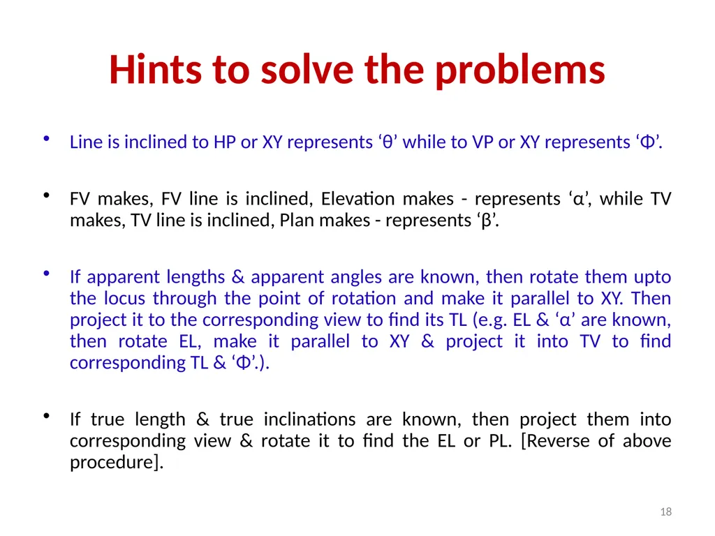
slide18. Hints to solve the problems Line is inclined to HP or XY represents ‘θ’ while to VP or XY represents ‘Φ’.
FV makes, FV line is inclined, Elevation makes - represents ‘α’, while TV makes, TV line is inclined, Plan makes - represents ‘β’.
If apparent lengths & apparent angles are known, then rotate them upto the locus through the point of rotation and make it parallel to XY. Then project it to the corresponding view to find its TL (e.g. EL & ‘α’ are known, then rotate EL, make it parallel to XY & project it into TV to find corresponding TL & ‘Φ’.).
If true length & true inclinations are known, then project them into corresponding view & rotate it to find the EL or PL. [Reverse of above procedure]. 18<br>
slide19. Marking Scheme Locating given data – 2M
Drawing complete Front View – 4M
Drawing complete Top View – 4M
Locating traces – 2M
Total: 12 Marks 19<br>
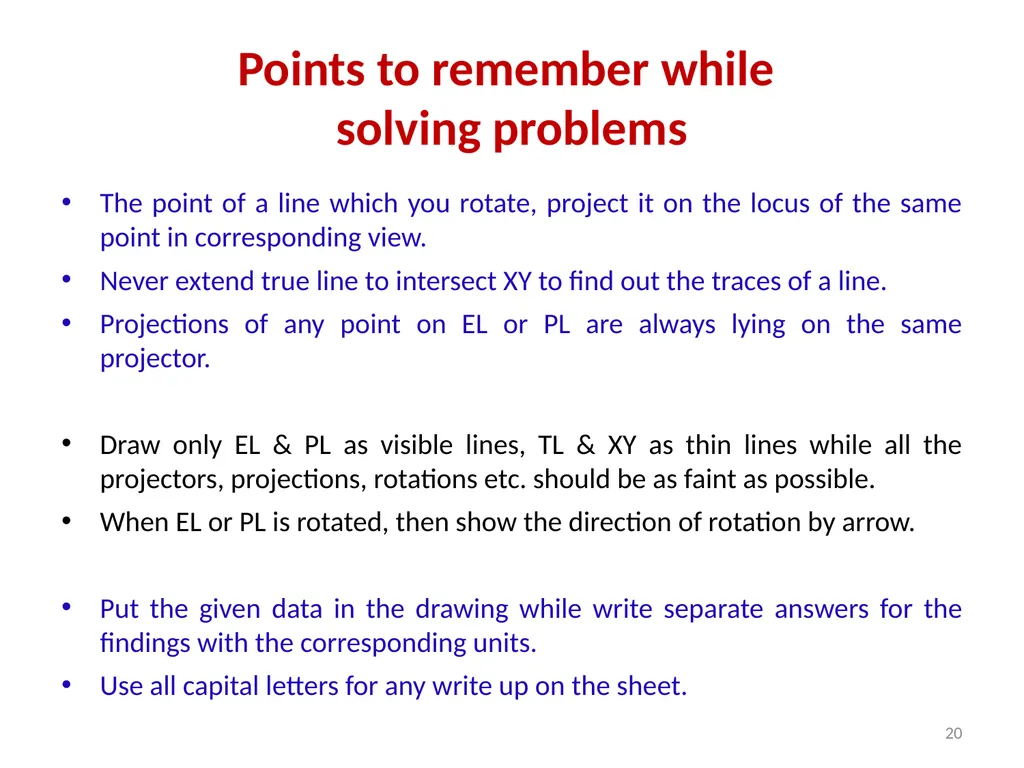
slide20. Points to remember while solving problems The point of a line which you rotate, project it on the locus of the same point in corresponding view.
Never extend true line to intersect XY to find out the traces of a line.
Projections of any point on EL or PL are always lying on the same projector.
Draw only EL & PL as visible lines, TL & XY as thin lines while all the projectors, projections, rotations etc. should be as faint as possible.
When EL or PL is rotated, then show the direction of rotation by arrow.
Put the given data in the drawing while write separate answers for the findings with the corresponding units.
Use all capital letters for any write up on the sheet. 20<br>

slide21. Thank You! 21<br>
Prof. Priyanka Narwade<br>
slide2. Learning objectives: Projections of a Point To Study concept of Principle Planes
To Understand theory of Projections
Analysis of a point in various quadrants
Analysis of a point in 1st quadrant, its different cases
Theory of projections by auxiliary plane method: AVP & AIP 2<br>
slide3. X Y 1st Quadrant 2nd Quadrant 3rdQuadrant 4th Quadrant F.V. 1ST Quad. 2nd Quad. 3rd Quad. 4th Quad. X Y Observer VP HP Observer 3<br>
slide4. a’ a A POINT A IN
1ST QUADRANT POINT A IN
2ND QUADRANT a’ a A a a’ POINT A IN
3RD QUADRANT A a a’ POINT A IN
4TH QUADRANT A 4<br>
slide5. A a a’ A a a’ A a a’ X Y PROJECTIONS OF A POINT IN FIRST QUADRANT. PICTORIAL
PRESENTATION PICTORIAL
PRESENTATION Fv above xy,
Tv below xy. Fv above xy,
Tv on xy. Fv on xy,
Tv below xy. 5<br>
slide6. Theory of Projections by Auxiliary Plane Method Auxiliary Vertical Plane [AVP] AVP is always perpendicular to HP, inclined to VP and hinged to HP (X1Y1).
AVP is used to find Auxiliary (New) FV which will lie on a line drawn from TV, perpendicular to New Reference Line (X1Y1), drawn at an angle of AVP to XY, and lies at a distance of its previous FV from its own XY. 6<br>
slide7. Theory of Projections by Auxiliary Plane Method AIP is always perpendicular to VP, inclined to HP and hinged to VP (X1Y1).
AIP is used to find Auxiliary (New) TV which will lie on a line drawn from FV, perpendicular to New Reference Line (X1Y1), drawn at an angle of AIP to XY, and lies at a distance of its previous TV from its own XY. Auxiliary Inclined Plane [AIP] 7<br>
slide8. Learning objectives:Projections of a Line To study the Concept of Line
To understand fundamentals of projections of a line
Analysis of a line in 1st quadrant, different cases
Traces of a line: HT & VT
Summarization of concepts & observations of a oblique line 8<br>
slide9. Projections of Line Line:
The shortest distance between two points
A locus of infinite number of points.
A segment of an arc with infinite radius
A one dimensional object
True Length:
Every line has only & only one True Length (TL).
TL of a line in FV, TV, SV remains the same.
Concept:
If any line is parallel to any one reference plane, then view obtained in that reference plane is always True Length.
When any one view of a line represents TL, then its correspondence view is always parallel to XY & is apparent length.
For example: If FV is a TL, then its corresponding view is TV as Plan Length (PL).
For example: If TV is a TL, then its corresponding view is FV as Elevation Length (EPL). 9<br>
slide10. F.V. T.V. a b TV FV For Fv For Tv For Tv For Fv 1. 2. A Line
perpendicular
to Hp
&
// to Vp A Line
// to Hp
&
// to Vp Orthographic Pattern Orthographic Pattern 10<br>
slide11. A Line inclined to Hp
and
parallel to Vp
(Pictorial presentation) A Line inclined to Vp
and
parallel to Hp
(Pictorial presentation) Ø F.V. T.V. 3. 4. Orthographic Projections 11<br>
slide12. A Line inclined to both
Hp and Vp
(Pictorial presentation) 5. 12<br>
slide13. b1 b1’ TL Here TV (ab) is not // to XY line
Hence it’s corresponding FV
a’ b’ is not showing
True Length &
True Inclination with Hp. In this sketch, TV is rotated
and made // to XY line.
Hence it’s corresponding
FV a’ b1’ Is showing
True Length
&
True Inclination with Hp. Note the procedure
When Fv & Tv known,
How to find True Length.
(Views are rotated to determine
True Length & it’s inclinations
with Hp & Vp). Note the procedure
When True Length is known,
How to locate FV & TV.
(Component a’b2’ of TL is drawn
which is further rotated
to determine FV) b’ TL Fv Orthographic Projections
Means Fv & Tv of Line AB
are shown below,
with their apparent Inclinations
& Here a’b1’ is component
of TL ab1 gives length of FV.
Hence it is brought Up to
Locus of a’ and further rotated
to get point b’. a’ b’ will be Fv.
Similarly drawing component
of other TL(a’b1‘) TV can be drawn. b1 b2’ 13<br>
slide14. Traces of Line Trace: Extension of apparent line intersecting to reference plane.
Horizontal Trace (HT): Extend EL to intersect XY at ‘h’, through ‘h’ draw the projector which will cut extension of PL to give HT.
Vertical Trace (VT): Extend PL to intersect XY at ‘v’, through ‘v’ draw the projector which will cut extension of EL to give VT.
Remember: EL (a’, b’), h, VT are collinear & lie on ‘α’ line.
PL (a, b), v, HT are collinear & lie on ‘β’ line, while ‘h’ & ‘v’ are always lie on XY. 14<br>
slide15. Traces of Line Line Parallel to HP & VP Line Parallel to VP &
Perpendicular to HP Line Parallel to HP &
Perpendicular to VP 15<br>
slide16. Traces of Line Line Parallel to VP &
inclined to HP Line Parallel to HP &
inclined to VP 16<br>
slide17. Projections of Line A Line inclined to both HP & VP a’ Point above HP
a Point in front of VP
b‘ Point above HP
b Point in front of VP
a’b’ Elevation or FV length, EL
ab Plan or TV length, PL
TL True length = a‘b’1 = ab1
α Apparent angle made by EL
Β Apparent angle made by PL
Θ True inclination with HP by TL
Φ True inclination with VP by TL
PD Projector distance parallel to XY
a‘a Lies on the same Projector
b‘b Lies on the same Projector
HT Horizontal trace
VT Vertical trace
a’, b’, h, VT are collinear & lies on EL
a, b, v, HT are collinear & lies on PL
h & v are always on XY 17<br>
slide18. Hints to solve the problems Line is inclined to HP or XY represents ‘θ’ while to VP or XY represents ‘Φ’.
FV makes, FV line is inclined, Elevation makes - represents ‘α’, while TV makes, TV line is inclined, Plan makes - represents ‘β’.
If apparent lengths & apparent angles are known, then rotate them upto the locus through the point of rotation and make it parallel to XY. Then project it to the corresponding view to find its TL (e.g. EL & ‘α’ are known, then rotate EL, make it parallel to XY & project it into TV to find corresponding TL & ‘Φ’.).
If true length & true inclinations are known, then project them into corresponding view & rotate it to find the EL or PL. [Reverse of above procedure]. 18<br>
slide19. Marking Scheme Locating given data – 2M
Drawing complete Front View – 4M
Drawing complete Top View – 4M
Locating traces – 2M
Total: 12 Marks 19<br>
slide20. Points to remember while solving problems The point of a line which you rotate, project it on the locus of the same point in corresponding view.
Never extend true line to intersect XY to find out the traces of a line.
Projections of any point on EL or PL are always lying on the same projector.
Draw only EL & PL as visible lines, TL & XY as thin lines while all the projectors, projections, rotations etc. should be as faint as possible.
When EL or PL is rotated, then show the direction of rotation by arrow.
Put the given data in the drawing while write separate answers for the findings with the corresponding units.
Use all capital letters for any write up on the sheet. 20<br>
slide21. Thank You! 21<br>