
Fiber Optic Gyroscope Systems Design 2 DC

Fiber Optic Gyroscope Systems Design 2 DC
1 / 1
Fiber Optic Gyroscope Systems Design 2 DC - slide 1 of 4 Fiber Optic Gyroscope Systems Design 2 DC - slide 2 of 4 Fiber Optic Gyroscope Systems Design 2 DC - slide 3 of 4 Fiber Optic Gyroscope Systems Design 2 DC - slide 4 of 4
Fiber Optic Gyroscope Systems Design 2 DC detection method FOG systems design The Sagnac phase shift (resulting from angular rotation) is applied to the CW direction and is calculated as follows: (8pi FiberCoilArea NumberOfCoils

Related Topics

Download this presentation From Below

"Fiber Optic Gyroscope Systems Design 2 DC" is the property of its rightful owner. Permission is granted to download and print the materials on this website for personal, non-commercial use only, and to display it on your personal computer provided you do not modify the materials and that you retain all copyright notices contained in the materials. By downloading content from our website, you accept the terms of this agreement.

Presentation Transcript

01
Fiber Optic Gyroscope Systems Design<br>
02
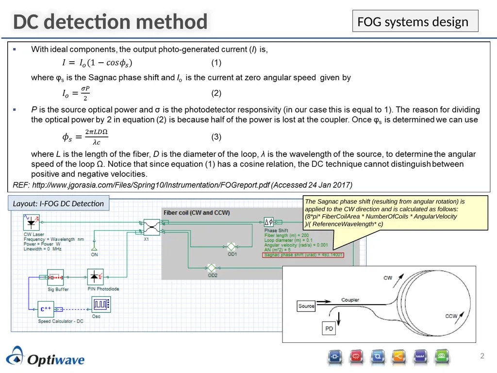
2 DC detection method FOG systems design The Sagnac phase shift (resulting from angular rotation) is applied to the CW direction and is calculated as follows:
(8*pi* FiberCoilArea * NumberOfCoils * AngularVelocity )/( ReferenceWavelength* c) Layout: I-FOG DC Detection<br>
03
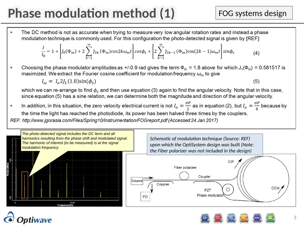
3 Phase modulation method (1) FOG systems design Schematic of modulation technique (Source: REF) upon which the OptiSystem design was built (Note: the Fiber polarizer was not included in the design) The photo-detected signal includes the DC term and all harmonics resulting from the phase shift and modulated signal. The harmonic of interest (to be measured) is at the signal modulation frequency<br>