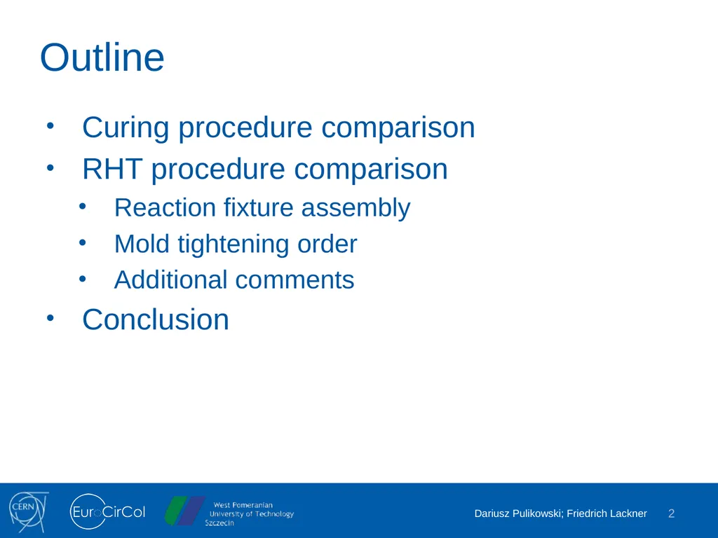
Harmonization of Curing and Reaction Heat Treatment procedures of 11 T F. Lackner, D. Pulikowski, J. Mazet, J. C. Perez, S. Luzieux in MDT and LMF sections 2018.02.05 Outline 2 Curing procedure comparison RHT procedure comparison Reaction
"Harmonization of Curing and Reaction Heat" is the property of its rightful owner. Permission is granted to
download and print the materials on this website for personal, non-commercial use only, and to display it
on your personal computer provided you do not modify the materials and that you retain all copyright
notices contained in the materials. By downloading content from our website, you accept the terms of this
agreement.
Presentation Transcript
01
Harmonization of Curing and Reaction Heat Treatment procedures of 11 T F. Lackner, D. Pulikowski, J. Mazet, J. C. Perez, S. Luzieux in MDT and LMF sections 2018.02.05<br>
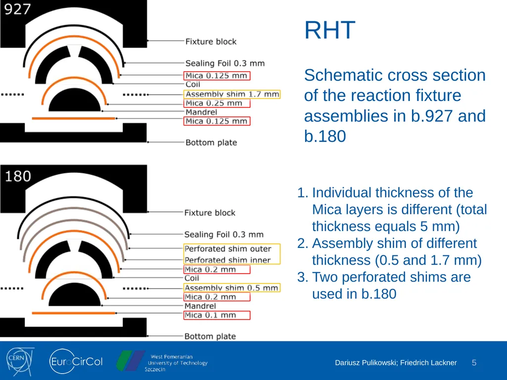
Schematic cross section of the reaction fixture assemblies in b.927 and b.180 Individual thickness of the Mica layers is different (total thickness equals 5 mm)
Assembly shim of different thickness (0.5 and 1.7 mm)
Two perforated shims are used in b.180<br>
06
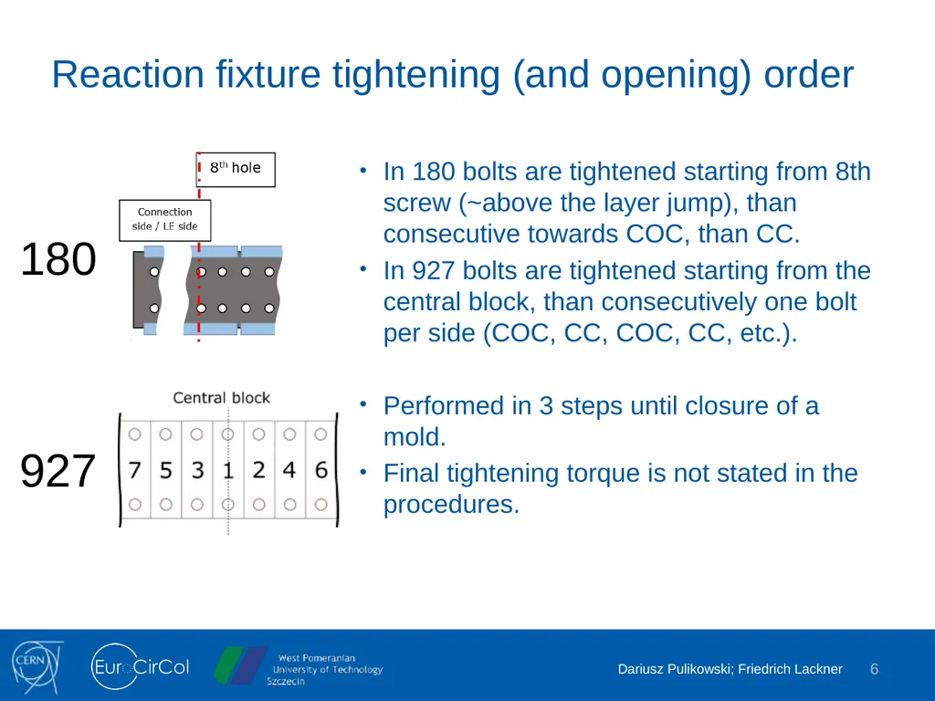
Reaction fixture tightening (and opening) order In 180 bolts are tightened starting from 8th screw (~above the layer jump), than consecutive towards COC, than CC.
In 927 bolts are tightened starting from the central block, than consecutively one bolt per side (COC, CC, COC, CC, etc.).
Performed in 3 steps until closure of a mold.
Final tightening torque is not stated in the procedures. 6 180 927<br>
07
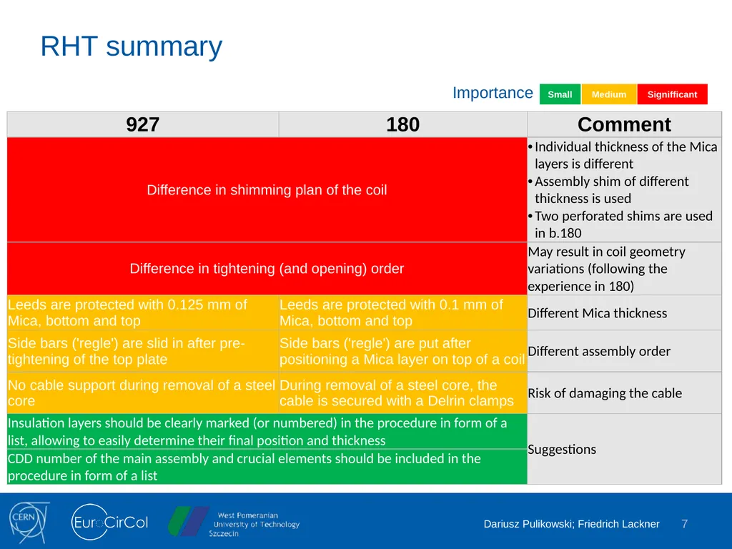
RHT summary 7 Importance<br>
08
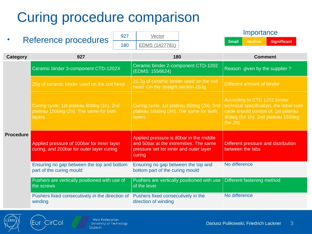
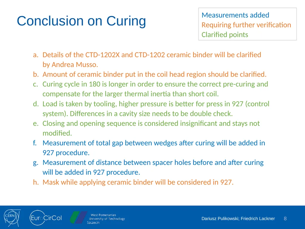
8 Conclusion on Curing Details of the CTD-1202X and CTD-1202 ceramic binder will be clarified by Andrea Musso.
Amount of ceramic binder put in the coil head region should be clarified.
Curing cycle in 180 is longer in order to ensure the correct pre-curing and compensate for the larger thermal inertia than short coil.
Load is taken by tooling, higher pressure is better for press in 927 (control system). Differences in a cavity size needs to be double check.
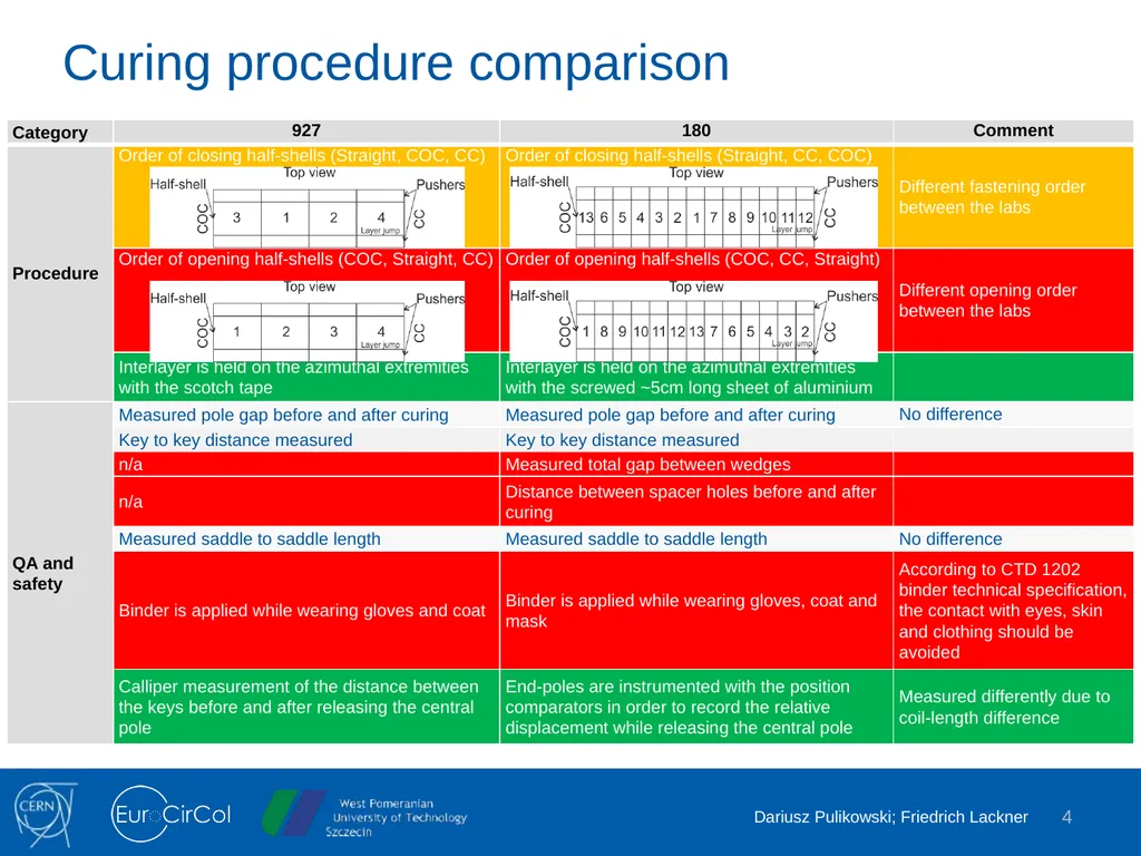
Closing and opening sequence is considered insignificant and stays not modified.
Measurement of total gap between wedges after curing will be added in 927 procedure.
Measurement of distance between spacer holes before and after curing will be added in 927 procedure.
Mask while applying ceramic binder will be considered in 927. Measurements added
Requiring further verification
Clarified points<br>
09
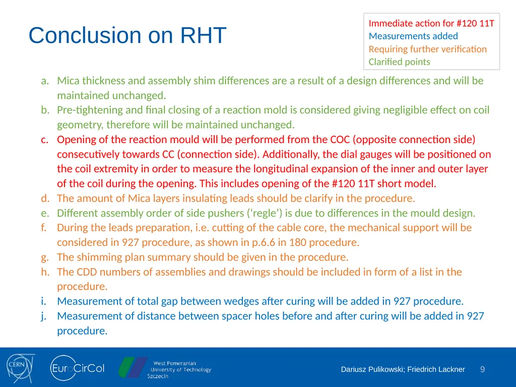
9 Conclusion on RHT Mica thickness and assembly shim differences are a result of a design differences and will be maintained unchanged.
Pre-tightening and final closing of a reaction mold is considered giving negligible effect on coil geometry, therefore will be maintained unchanged.
Opening of the reaction mould will be performed from the COC (opposite connection side) consecutively towards CC (connection side). Additionally, the dial gauges will be positioned on the coil extremity in order to measure the longitudinal expansion of the inner and outer layer of the coil during the opening. This includes opening of the #120 11T short model.
The amount of Mica layers insulating leads should be clarify in the procedure.
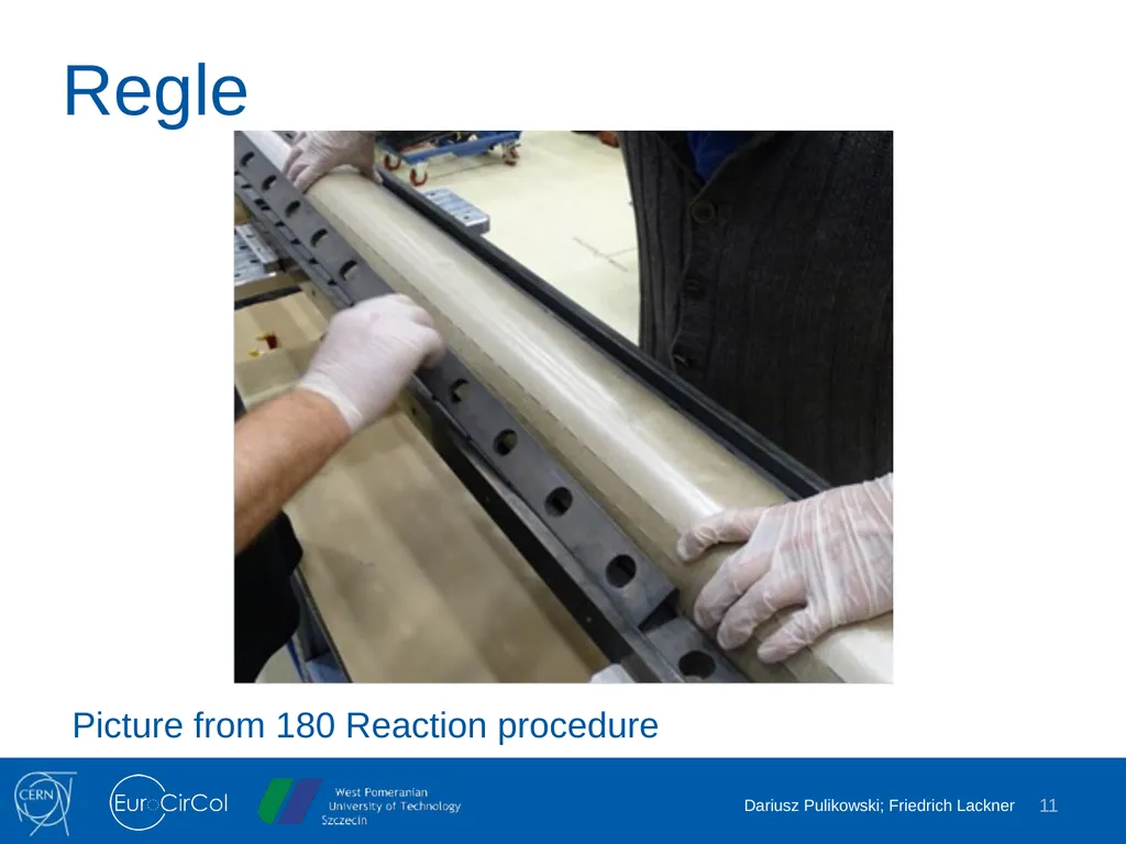
Different assembly order of side pushers (‘regle’) is due to differences in the mould design.
During the leads preparation, i.e. cutting of the cable core, the mechanical support will be considered in 927 procedure, as shown in p.6.6 in 180 procedure.
The shimming plan summary should be given in the procedure.
The CDD numbers of assemblies and drawings should be included in form of a list in the procedure.
Measurement of total gap between wedges after curing will be added in 927 procedure.
Measurement of distance between spacer holes before and after curing will be added in 927 procedure. Immediate action for #120 11T
Measurements added
Requiring further verification
Clarified points<br>
10
10 Thank you<br>
11
Regle Picture from 180 Reaction procedure 11<br>
12
Additional coil measurements QC for winding and curing 12<br>
13
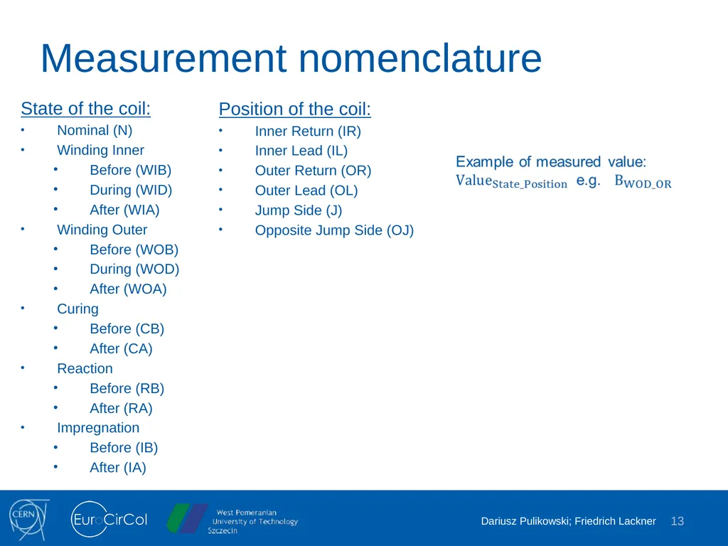
Measurement nomenclature State of the coil:
Nominal (N)
Winding Inner
Before (WIB)
During (WID)
After (WIA)
Winding Outer
Before (WOB)
During (WOD)
After (WOA)
Curing
Before (CB)
After (CA)
Reaction
Before (RB)
After (RA)
Impregnation
Before (IB)
After (IA) 13 Position of the coil:
Inner Return (IR)
Inner Lead (IL)
Outer Return (OR)
Outer Lead (OL)
Jump Side (J)
Opposite Jump Side (OJ)<br>
14
Geometrical QC MQXFB CR107 14 Additional geometrical measurements performed during MQXFB CR107 coil production. Height reference Pole Cable Mandrel Bottom Top Image Wedge gap Pole gap Laser tracker Protrusion<br>
15
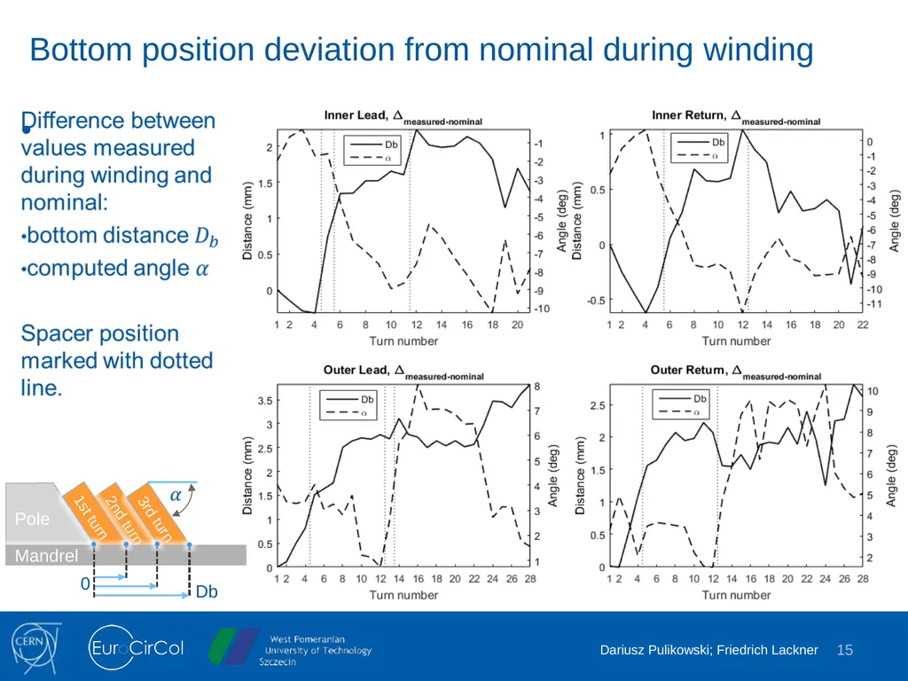
Bottom position deviation from nominal during winding 15<br>
16
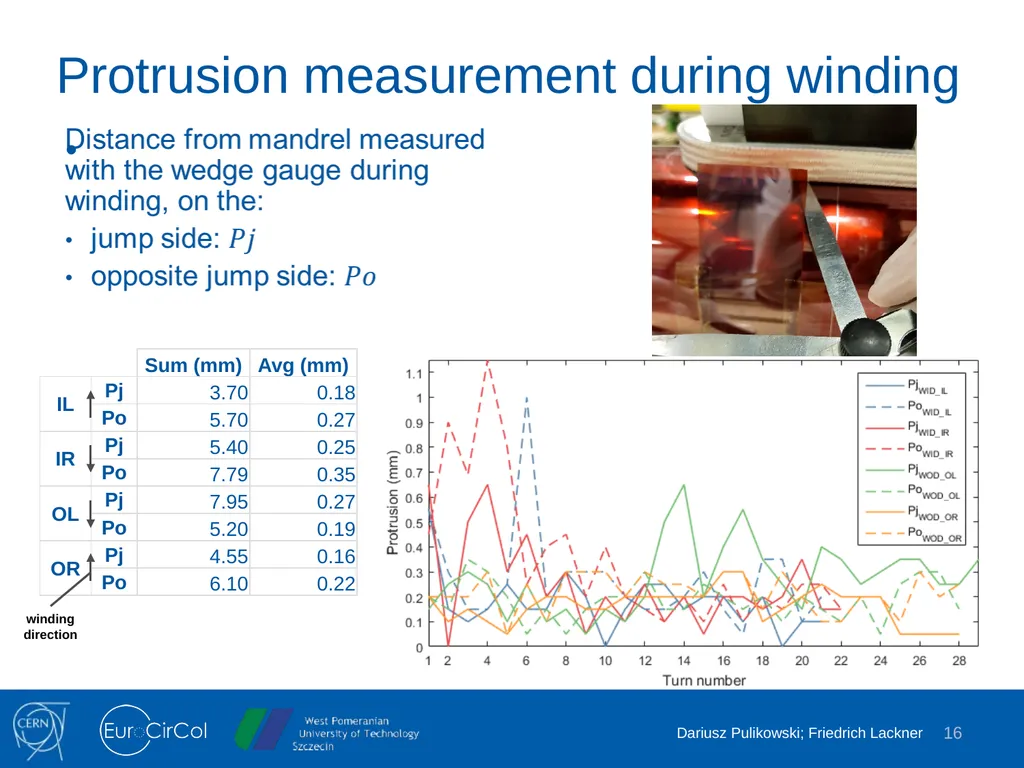
Protrusion measurement during winding 16 winding direction<br>
17
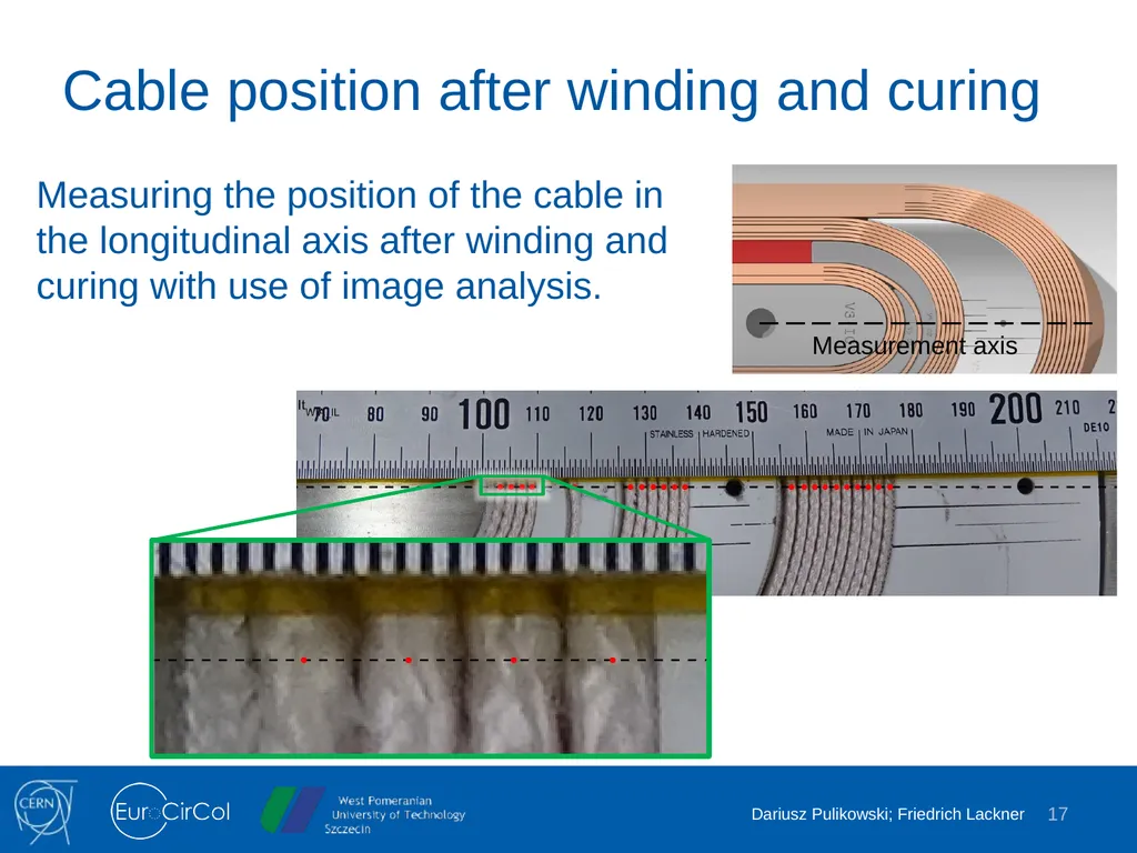
Cable position after winding and curing Measuring the position of the cable in the longitudinal axis after winding and curing with use of image analysis. 17<br>
18
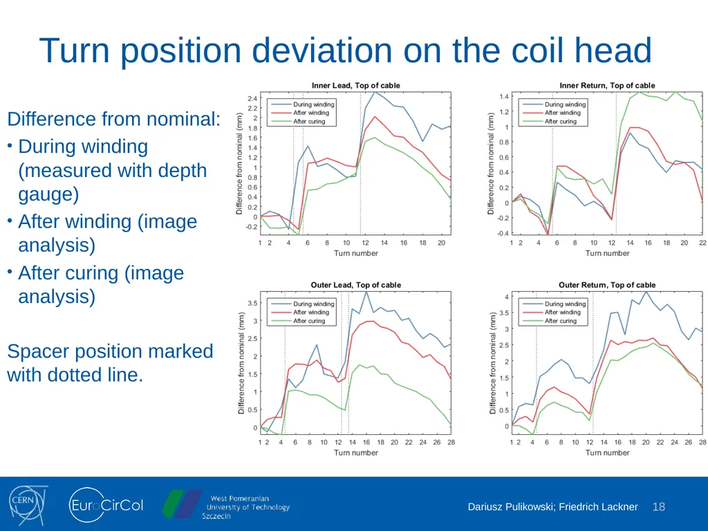
Turn position deviation on the coil head Difference from nominal:
During winding (measured with depth gauge)
After winding (image analysis)
After curing (image analysis)