
Ion induced pressure instability: the threat for
LV
Published · 33 slides · 0 views

1 / 1






Description
Ion induced pressure instability: the threat for positively charged beams O.B. Malyshev ASTeC Vacuum Science Group, STFC Daresbury Laboratory, UK ECLOUD22, Isola dElba, Italy, 26-30 Sep. 2022 What is the ion induced pressure instability?
Related Topics
Share
Embed code
Download this presentation From Below
"Ion induced pressure instability: the threat for" is the property of its rightful owner. Permission is granted to download and print the materials on this website for personal, non-commercial use only, and to display it on your personal computer provided you do not modify the materials and that you retain all copyright notices contained in the materials. By downloading content from our website, you accept the terms of this agreement.
Presentation Transcript
01
Ion induced pressure instability:
the threat for positively charged beams O.B. Malyshev
ASTeC Vacuum Science Group,
STFC Daresbury Laboratory, UK
ECLOUD’22, Isola d'Elba, Italy, 26-30 Sep. 2022<br>
ASTeC Vacuum Science Group,
STFC Daresbury Laboratory, UK
ECLOUD’22, Isola d'Elba, Italy, 26-30 Sep. 2022<br>
02
What is the ion induced pressure instability?<br>
03
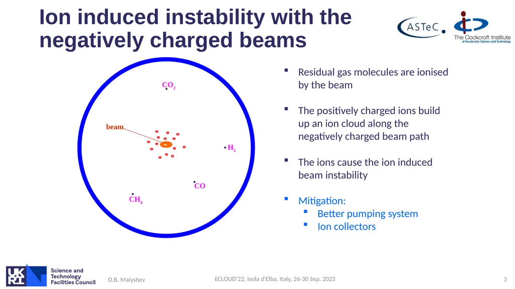
Ion induced instability with the negatively charged beams O.B. Malyshev ECLOUD’22, Isola d'Elba, Italy, 26-30 Sep. 2022 3 CO H2 CH4 CO2 beam Residual gas molecules are ionised by the beam
The positively charged ions build up an ion cloud along the negatively charged beam path
The ions cause the ion induced beam instability
Mitigation:
Better pumping system
Ion collectors + + + + + + + + + + + + + +<br>
The positively charged ions build up an ion cloud along the negatively charged beam path
The ions cause the ion induced beam instability
Mitigation:
Better pumping system
Ion collectors + + + + + + + + + + + + + +<br>
04
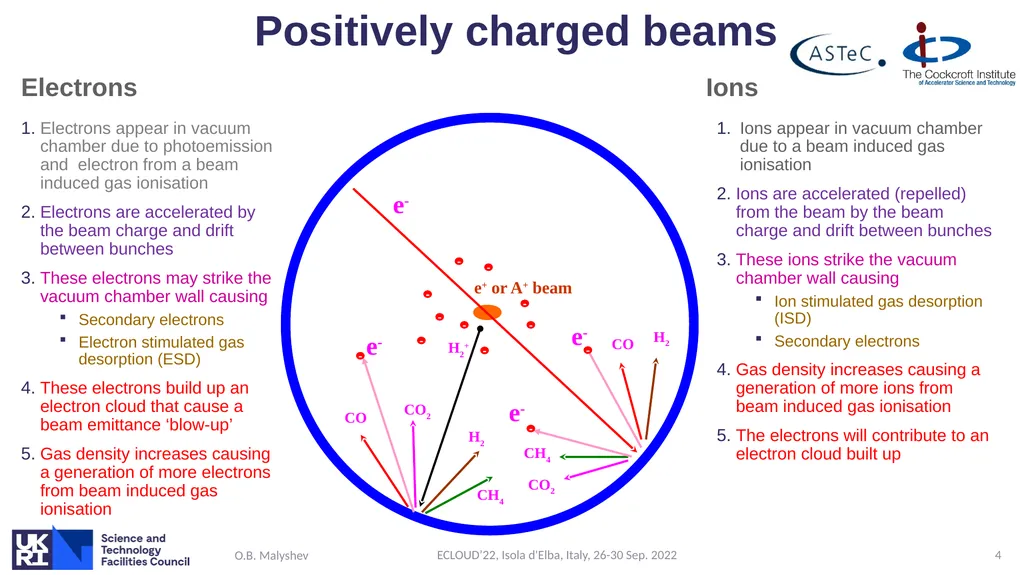
Positively charged beams Electrons Electrons appear in vacuum chamber due to photoemission and electron from a beam induced gas ionisation
Electrons are accelerated by the beam charge and drift between bunches
These electrons may strike the vacuum chamber wall causing
Secondary electrons
Electron stimulated gas desorption (ESD)
These electrons build up an electron cloud that cause a beam emittance ‘blow-up’
Gas density increases causing a generation of more electrons from beam induced gas ionisation Ions Ions appear in vacuum chamber due to a beam induced gas ionisation
Ions are accelerated (repelled) from the beam by the beam charge and drift between bunches
These ions strike the vacuum chamber wall causing
Ion stimulated gas desorption (ISD)
Secondary electrons
Gas density increases causing a generation of more ions from beam induced gas ionisation
The electrons will contribute to an electron cloud built up O.B. Malyshev ECLOUD’22, Isola d'Elba, Italy, 26-30 Sep. 2022 4 e- CO H2 CH4 CO2 e- e- e+ or A+ beam H2+ CO H2 CH4 CO2 e- <br>
Electrons are accelerated by the beam charge and drift between bunches
These electrons may strike the vacuum chamber wall causing
Secondary electrons
Electron stimulated gas desorption (ESD)
These electrons build up an electron cloud that cause a beam emittance ‘blow-up’
Gas density increases causing a generation of more electrons from beam induced gas ionisation Ions Ions appear in vacuum chamber due to a beam induced gas ionisation
Ions are accelerated (repelled) from the beam by the beam charge and drift between bunches
These ions strike the vacuum chamber wall causing
Ion stimulated gas desorption (ISD)
Secondary electrons
Gas density increases causing a generation of more ions from beam induced gas ionisation
The electrons will contribute to an electron cloud built up O.B. Malyshev ECLOUD’22, Isola d'Elba, Italy, 26-30 Sep. 2022 4 e- CO H2 CH4 CO2 e- e- e+ or A+ beam H2+ CO H2 CH4 CO2 e- <br>
05
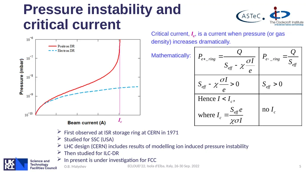
Pressure instability and critical current O.B. Malyshev ECLOUD’22, Isola d'Elba, Italy, 26-30 Sep. 2022 5 Critical current, Ic, is a current when pressure (or gas density) increases dramatically.
Mathematically: First observed at ISR storage ring at CERN in 1971
Studied for SSC (USA)
LHC design (CERN) includes results of modelling ion induced pressure instability
Then studied for ILC-DR
In present is under investigation for FCC<br>
Mathematically: First observed at ISR storage ring at CERN in 1971
Studied for SSC (USA)
LHC design (CERN) includes results of modelling ion induced pressure instability
Then studied for ILC-DR
In present is under investigation for FCC<br>
06
Theoretical model<br>
07
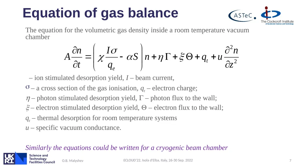
Equation of gas balance The equation for the volumetric gas density inside a room temperature vacuum chamber
– ion stimulated desorption yield, I – beam current,
– a cross section of the gas ionisation, qt – electron charge;
h – photon stimulated desorption yield, G – photon flux to the wall;
– electron stimulated desorption yield, – electron flux to the wall;
qt – thermal desorption for room temperature systems
u – specific vacuum conductance.
Similarly the equations could be written for a cryogenic beam chamber O.B. Malyshev ECLOUD’22, Isola d'Elba, Italy, 26-30 Sep. 2022 7<br>
– ion stimulated desorption yield, I – beam current,
– a cross section of the gas ionisation, qt – electron charge;
h – photon stimulated desorption yield, G – photon flux to the wall;
– electron stimulated desorption yield, – electron flux to the wall;
qt – thermal desorption for room temperature systems
u – specific vacuum conductance.
Similarly the equations could be written for a cryogenic beam chamber O.B. Malyshev ECLOUD’22, Isola d'Elba, Italy, 26-30 Sep. 2022 7<br>
08
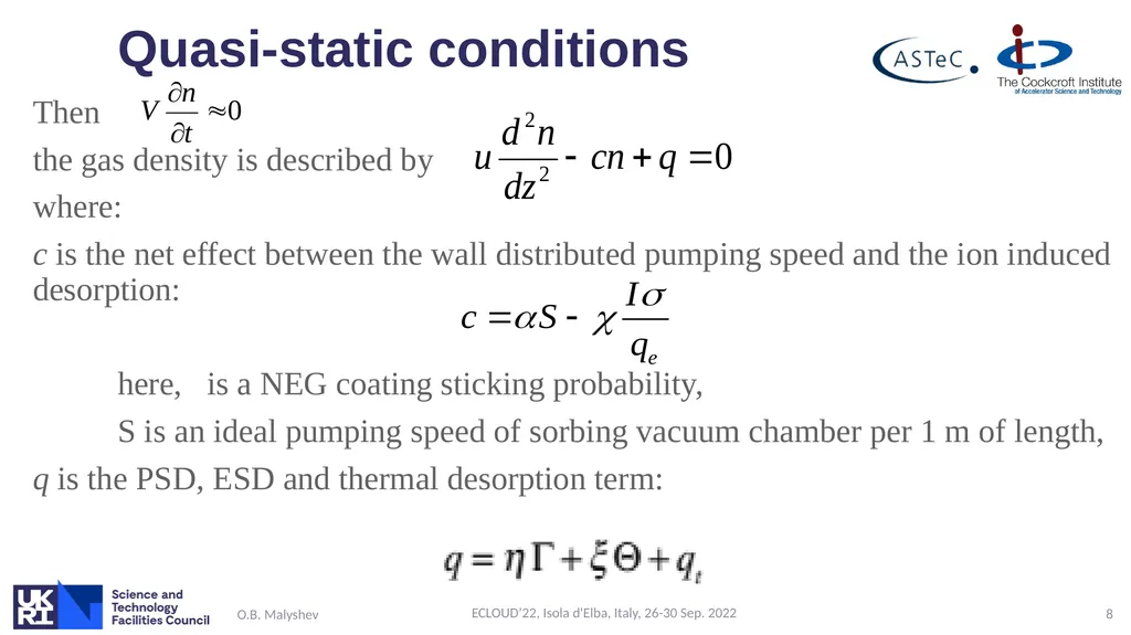
Quasi-static conditions Then
the gas density is described by
where:
c is the net effect between the wall distributed pumping speed and the ion induced desorption:
here, is a NEG coating sticking probability,
S is an ideal pumping speed of sorbing vacuum chamber per 1 m of length,
q is the PSD, ESD and thermal desorption term: O.B. Malyshev ECLOUD’22, Isola d'Elba, Italy, 26-30 Sep. 2022 8<br>
the gas density is described by
where:
c is the net effect between the wall distributed pumping speed and the ion induced desorption:
here, is a NEG coating sticking probability,
S is an ideal pumping speed of sorbing vacuum chamber per 1 m of length,
q is the PSD, ESD and thermal desorption term: O.B. Malyshev ECLOUD’22, Isola d'Elba, Italy, 26-30 Sep. 2022 8<br>
09
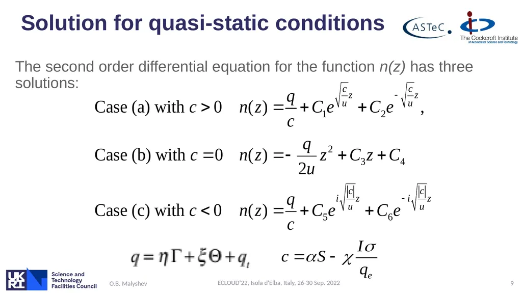
Solution for quasi-static conditions The second order differential equation for the function n(z) has three solutions: O.B. Malyshev ECLOUD’22, Isola d'Elba, Italy, 26-30 Sep. 2022 9<br>
10
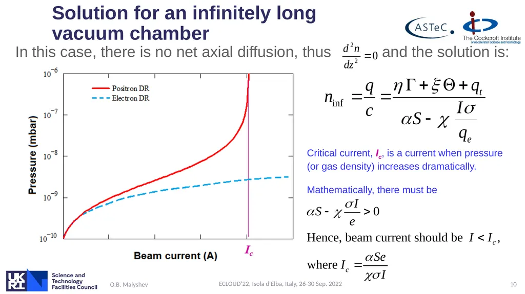
Solution for an infinitely long vacuum chamber In this case, there is no net axial diffusion, thus and the solution is: O.B. Malyshev ECLOUD’22, Isola d'Elba, Italy, 26-30 Sep. 2022 10 Critical current, Ic, is a current when pressure (or gas density) increases dramatically.
Mathematically, there must be<br>
Mathematically, there must be<br>
11
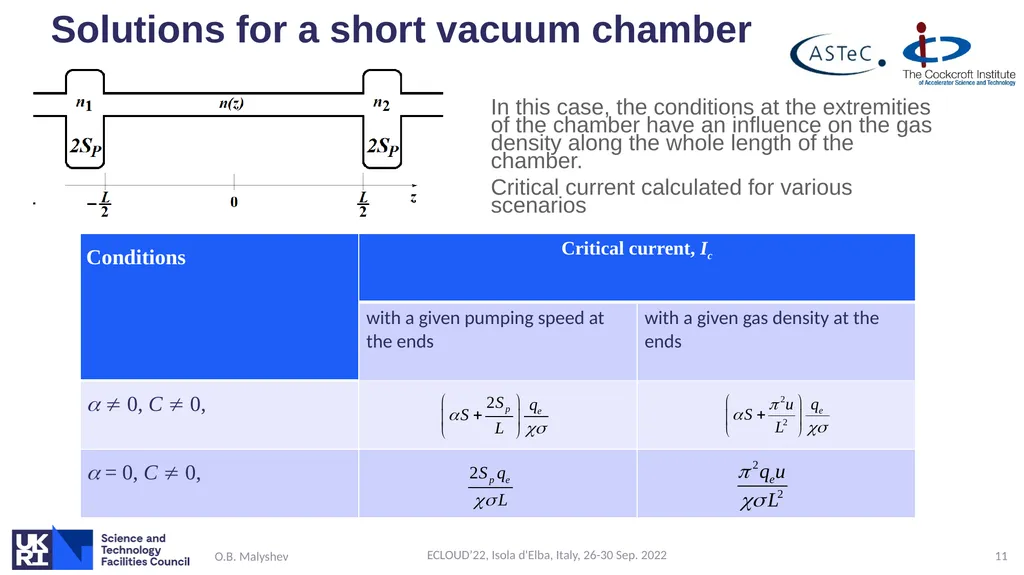
Solutions for a short vacuum chamber In this case, the conditions at the extremities of the chamber have an influence on the gas density along the whole length of the chamber.
Critical current calculated for various scenarios O.B. Malyshev ECLOUD’22, Isola d'Elba, Italy, 26-30 Sep. 2022 11<br>
Critical current calculated for various scenarios O.B. Malyshev ECLOUD’22, Isola d'Elba, Italy, 26-30 Sep. 2022 11<br>
12
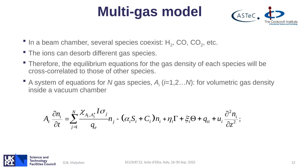
Multi-gas model In a beam chamber, several species coexist: H2, CO, CO2, etc.
The ions can desorb different gas species.
Therefore, the equilibrium equations for the gas density of each species will be cross-correlated to those of other species.
A system of equations for N gas species, Ai (i=1,2…N): for volumetric gas density inside a vacuum chamber O.B. Malyshev ECLOUD’22, Isola d'Elba, Italy, 26-30 Sep. 2022 12<br>
The ions can desorb different gas species.
Therefore, the equilibrium equations for the gas density of each species will be cross-correlated to those of other species.
A system of equations for N gas species, Ai (i=1,2…N): for volumetric gas density inside a vacuum chamber O.B. Malyshev ECLOUD’22, Isola d'Elba, Italy, 26-30 Sep. 2022 12<br>
13
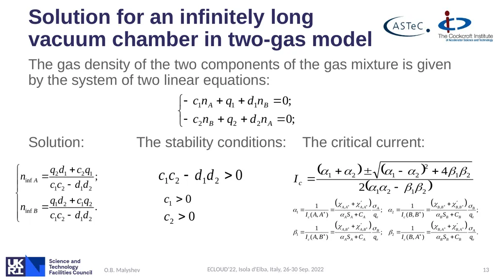
Solution for an infinitely long vacuum chamber in two-gas model The gas density of the two components of the gas mixture is given by the system of two linear equations:
Solution: The stability conditions: The critical current: O.B. Malyshev ECLOUD’22, Isola d'Elba, Italy, 26-30 Sep. 2022 13<br>
Solution: The stability conditions: The critical current: O.B. Malyshev ECLOUD’22, Isola d'Elba, Italy, 26-30 Sep. 2022 13<br>
14
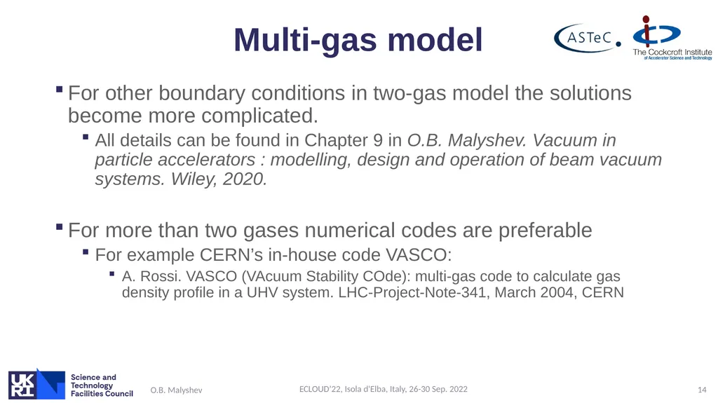
Multi-gas model For other boundary conditions in two-gas model the solutions become more complicated.
All details can be found in Chapter 9 in O.B. Malyshev. Vacuum in particle accelerators : modelling, design and operation of beam vacuum systems. Wiley, 2020.
For more than two gases numerical codes are preferable
For example CERN’s in-house code VASCO:
A. Rossi. VASCO (VAcuum Stability COde): multi-gas code to calculate gas density profile in a UHV system. LHC-Project-Note-341, March 2004, CERN O.B. Malyshev ECLOUD’22, Isola d'Elba, Italy, 26-30 Sep. 2022 14<br>
All details can be found in Chapter 9 in O.B. Malyshev. Vacuum in particle accelerators : modelling, design and operation of beam vacuum systems. Wiley, 2020.
For more than two gases numerical codes are preferable
For example CERN’s in-house code VASCO:
A. Rossi. VASCO (VAcuum Stability COde): multi-gas code to calculate gas density profile in a UHV system. LHC-Project-Note-341, March 2004, CERN O.B. Malyshev ECLOUD’22, Isola d'Elba, Italy, 26-30 Sep. 2022 14<br>
15
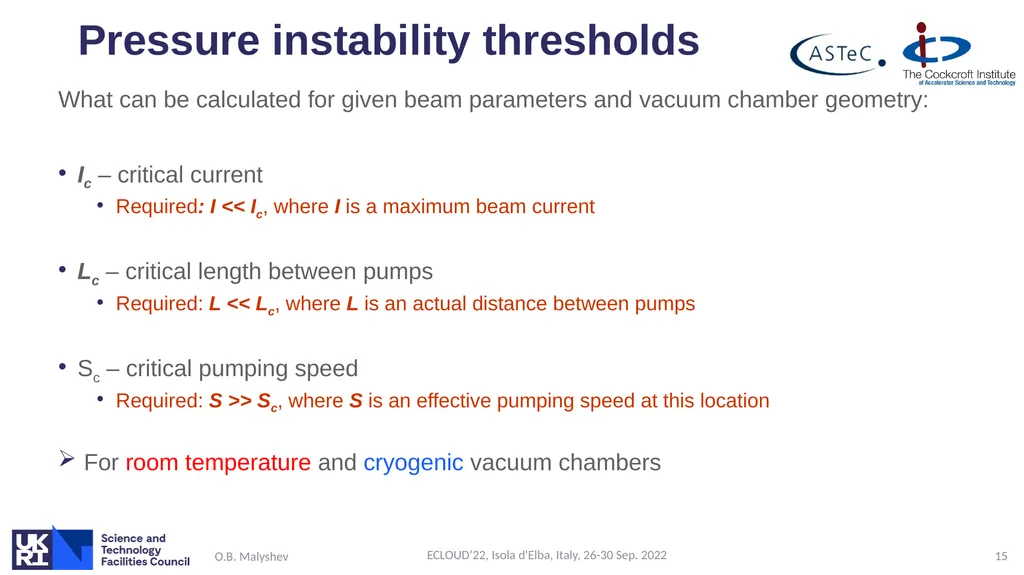
Pressure instability thresholds What can be calculated for given beam parameters and vacuum chamber geometry:
Ic – critical current
Required: I << Ic, where I is a maximum beam current
Lc – critical length between pumps
Required: L << Lc, where L is an actual distance between pumps
Sc – critical pumping speed
Required: S >> Sc, where S is an effective pumping speed at this location
For room temperature and cryogenic vacuum chambers O.B. Malyshev ECLOUD’22, Isola d'Elba, Italy, 26-30 Sep. 2022 15<br>
Ic – critical current
Required: I << Ic, where I is a maximum beam current
Lc – critical length between pumps
Required: L << Lc, where L is an actual distance between pumps
Sc – critical pumping speed
Required: S >> Sc, where S is an effective pumping speed at this location
For room temperature and cryogenic vacuum chambers O.B. Malyshev ECLOUD’22, Isola d'Elba, Italy, 26-30 Sep. 2022 15<br>
16
Luck of experimental data<br>
17
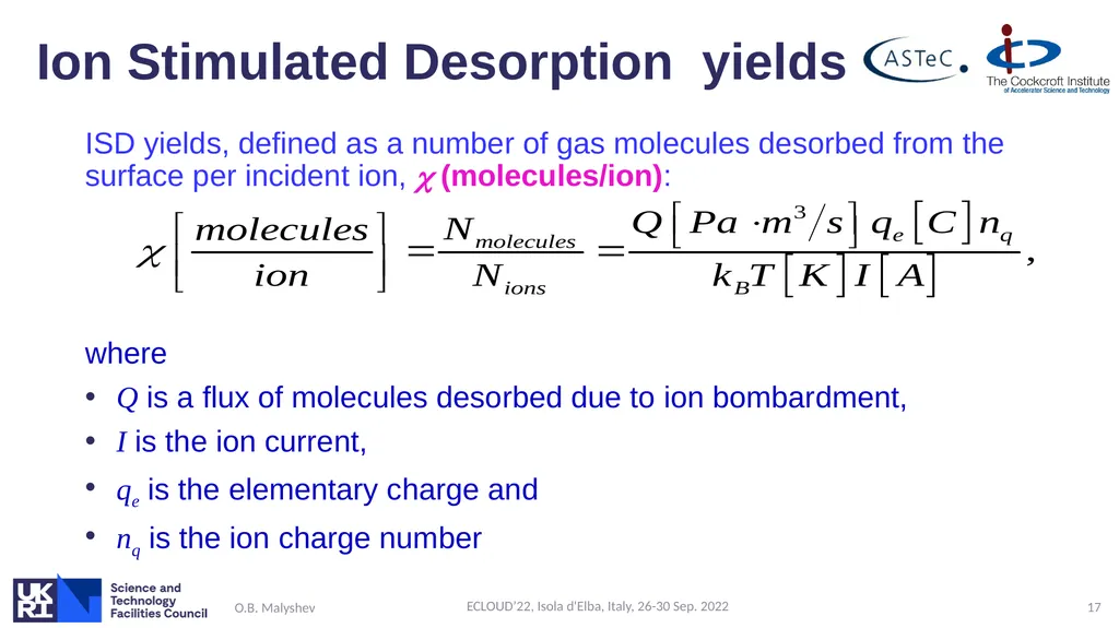
Ion Stimulated Desorption yields ISD yields, defined as a number of gas molecules desorbed from the surface per incident ion, (molecules/ion):
where
Q is a flux of molecules desorbed due to ion bombardment,
I is the ion current,
qe is the elementary charge and
nq is the ion charge number O.B. Malyshev ECLOUD’22, Isola d'Elba, Italy, 26-30 Sep. 2022 17<br>
where
Q is a flux of molecules desorbed due to ion bombardment,
I is the ion current,
qe is the elementary charge and
nq is the ion charge number O.B. Malyshev ECLOUD’22, Isola d'Elba, Italy, 26-30 Sep. 2022 17<br>
18
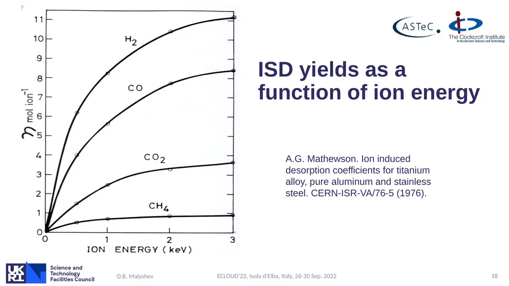
ISD yields as a function of ion energy O.B. Malyshev ECLOUD’22, Isola d'Elba, Italy, 26-30 Sep. 2022 18 A.G. Mathewson. Ion induced desorption coefficients for titanium alloy, pure aluminum and stainless steel. CERN-ISR-VA/76-5 (1976).<br>
19
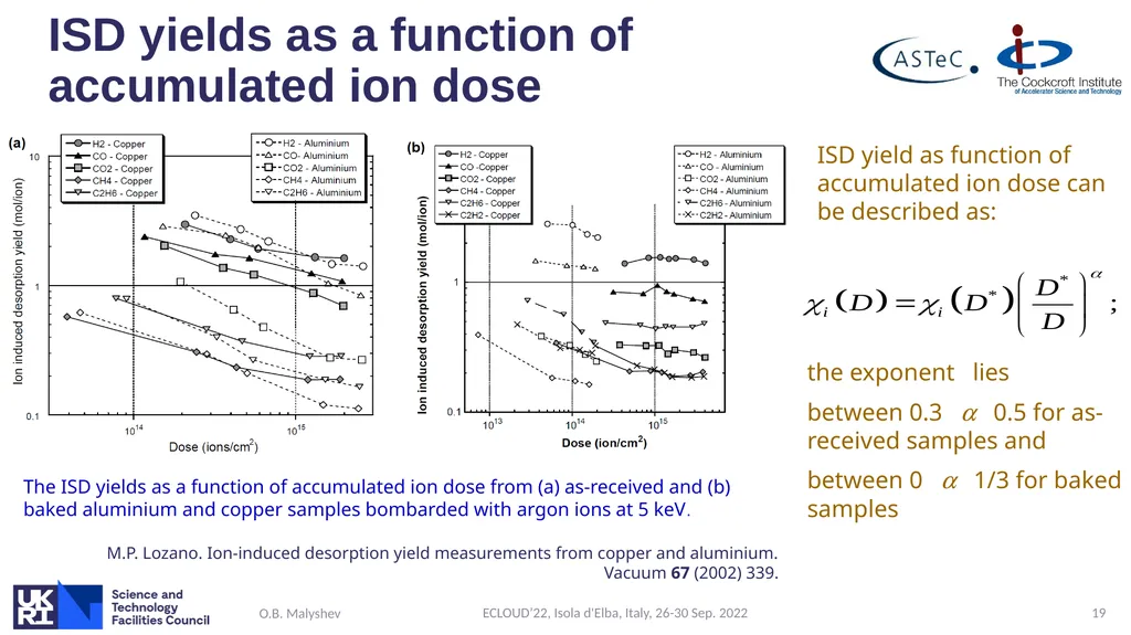
ISD yields as a function of accumulated ion dose O.B. Malyshev ECLOUD’22, Isola d'Elba, Italy, 26-30 Sep. 2022 19 The ISD yields as a function of accumulated ion dose from (a) as-received and (b) baked aluminium and copper samples bombarded with argon ions at 5 keV.
M.P. Lozano. Ion-induced desorption yield measurements from copper and aluminium.
Vacuum 67 (2002) 339. ISD yield as function of accumulated ion dose can be described as: the exponent lies
between 0.3 a 0.5 for as-received samples and
between 0 a 1/3 for baked samples<br>
M.P. Lozano. Ion-induced desorption yield measurements from copper and aluminium.
Vacuum 67 (2002) 339. ISD yield as function of accumulated ion dose can be described as: the exponent lies
between 0.3 a 0.5 for as-received samples and
between 0 a 1/3 for baked samples<br>
20
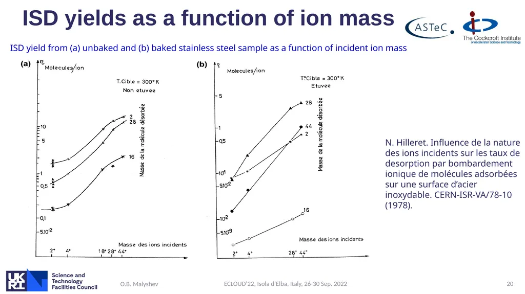
ISD yields as a function of ion mass O.B. Malyshev ECLOUD’22, Isola d'Elba, Italy, 26-30 Sep. 2022 20 N. Hilleret. Influence de la nature des ions incidents sur les taux de desorption par bombardement ionique de molécules adsorbées sur une surface d’acier inoxydable. CERN-ISR-VA/78-10 (1978). ISD yield from (a) unbaked and (b) baked stainless steel sample as a function of incident ion mass<br>
21
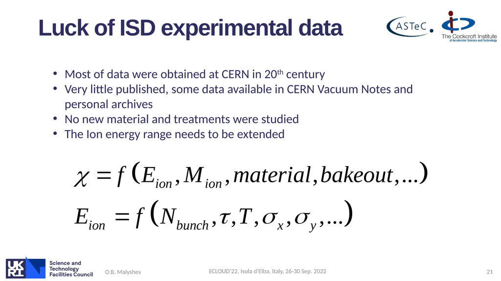
Luck of ISD experimental data O.B. Malyshev ECLOUD’22, Isola d'Elba, Italy, 26-30 Sep. 2022 21 Most of data were obtained at CERN in 20th century
Very little published, some data available in CERN Vacuum Notes and personal archives
No new material and treatments were studied
The Ion energy range needs to be extended<br>
Very little published, some data available in CERN Vacuum Notes and personal archives
No new material and treatments were studied
The Ion energy range needs to be extended<br>
22
What is energy of ion hitting vacuum chamber walls?<br>
23
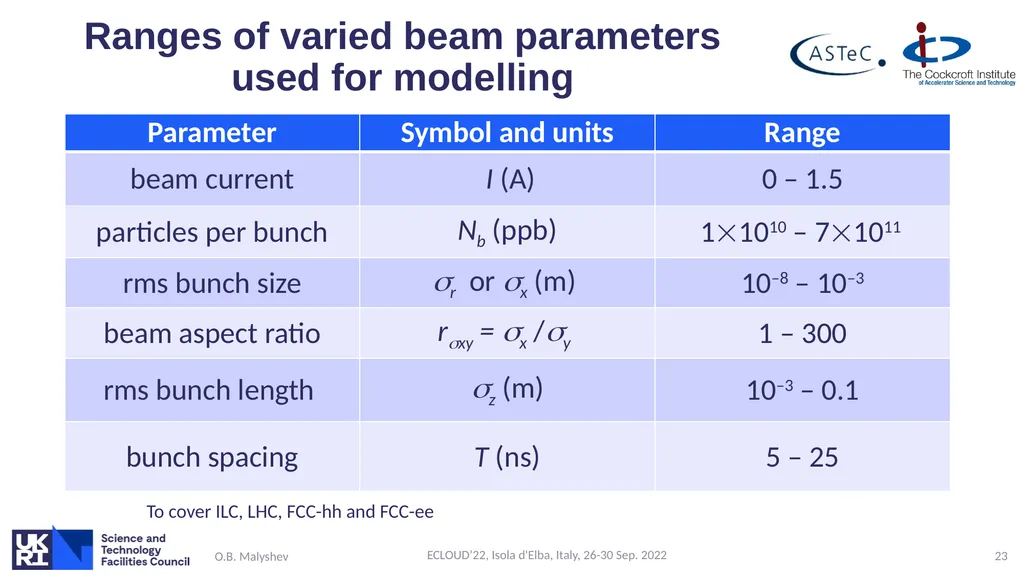
Ranges of varied beam parameters used for modelling O.B. Malyshev ECLOUD’22, Isola d'Elba, Italy, 26-30 Sep. 2022 23 To cover ILC, LHC, FCC-hh and FCC-ee<br>
24
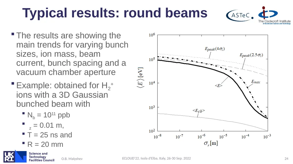
Typical results: round beams The results are showing the main trends for varying bunch sizes, ion mass, beam current, bunch spacing and a vacuum chamber aperture
Example: obtained for H2+ ions with a 3D Gaussian bunched beam with
Nb = 1011 ppb
z = 0.01 m,
T = 25 ns and
R = 20 mm O.B. Malyshev ECLOUD’22, Isola d'Elba, Italy, 26-30 Sep. 2022 24<br>
Example: obtained for H2+ ions with a 3D Gaussian bunched beam with
Nb = 1011 ppb
z = 0.01 m,
T = 25 ns and
R = 20 mm O.B. Malyshev ECLOUD’22, Isola d'Elba, Italy, 26-30 Sep. 2022 24<br>
25
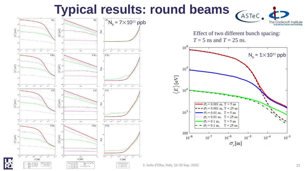
Typical results: round beams O.B. Malyshev ECLOUD’22, Isola d'Elba, Italy, 26-30 Sep. 2022 25 Nb = 71011 ppb Effect of two different bunch spacing:
T = 5 ns and T = 25 ns. Nb = 11011 ppb<br>
T = 5 ns and T = 25 ns. Nb = 11011 ppb<br>
26
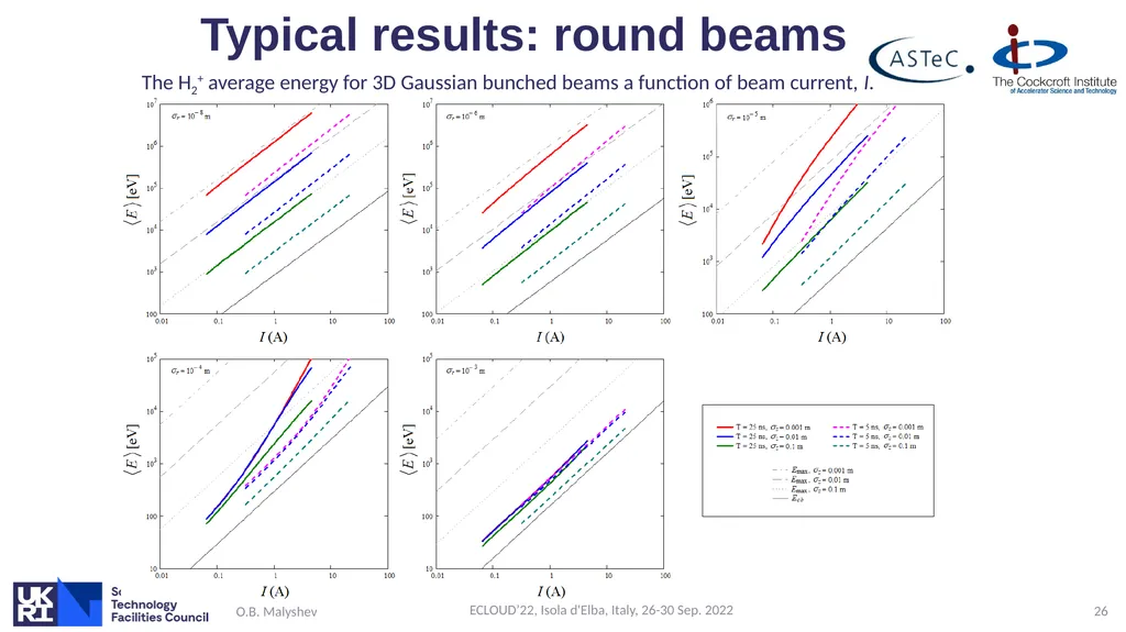
Typical results: round beams O.B. Malyshev ECLOUD’22, Isola d'Elba, Italy, 26-30 Sep. 2022 26 The H2+ average energy for 3D Gaussian bunched beams a function of beam current, I.<br>
27
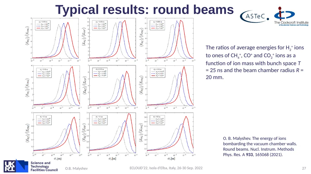
Typical results: round beams O.B. Malyshev ECLOUD’22, Isola d'Elba, Italy, 26-30 Sep. 2022 27 The ratios of average energies for H2+ ions to ones of CH4+, CO+ and CO2+ ions as a function of ion mass with bunch space T = 25 ns and the beam chamber radius R = 20 mm. O. B. Malyshev. The energy of ions bombarding the vacuum chamber walls. Round beams. Nucl. Instrum. Methods Phys. Res. A 933, 165068 (2021).<br>
28
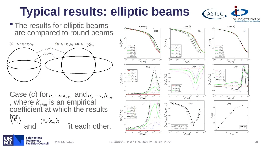
Typical results: elliptic beams The results for elliptic beams are compared to round beams
Case (c) for and , where kshift is an empirical coefficient at which the results for
and fit each other. O.B. Malyshev ECLOUD’22, Isola d'Elba, Italy, 26-30 Sep. 2022 28<br>
Case (c) for and , where kshift is an empirical coefficient at which the results for
and fit each other. O.B. Malyshev ECLOUD’22, Isola d'Elba, Italy, 26-30 Sep. 2022 28<br>
29
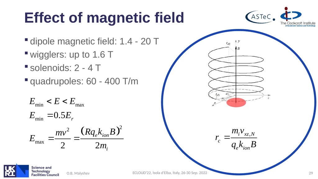
Effect of magnetic field dipole magnetic field: 1.4 - 20 T
wigglers: up to 1.6 T
solenoids: 2 - 4 T
quadrupoles: 60 - 400 T/m O.B. Malyshev ECLOUD’22, Isola d'Elba, Italy, 26-30 Sep. 2022 29<br>
wigglers: up to 1.6 T
solenoids: 2 - 4 T
quadrupoles: 60 - 400 T/m O.B. Malyshev ECLOUD’22, Isola d'Elba, Italy, 26-30 Sep. 2022 29<br>
30
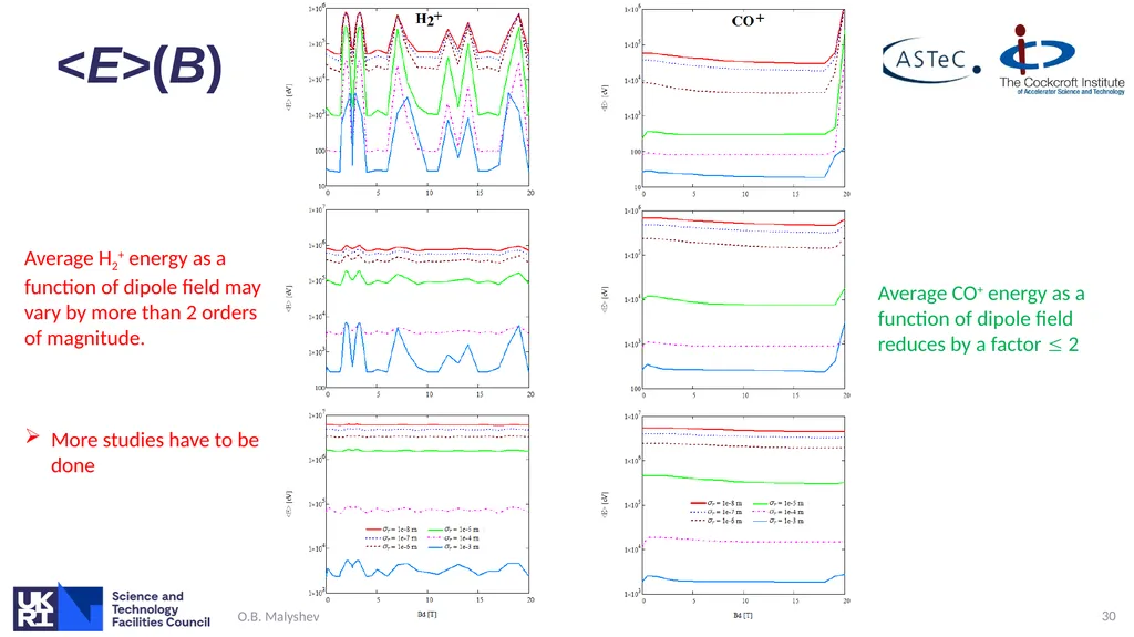
<E>(B) O.B. Malyshev ECLOUD’22, Isola d'Elba, Italy, 26-30 Sep. 2022 30 Average H2+ energy as a function of dipole field may vary by more than 2 orders of magnitude.
More studies have to be done Average CO+ energy as a function of dipole field reduces by a factor 2<br>
More studies have to be done Average CO+ energy as a function of dipole field reduces by a factor 2<br>
31
Conclusions Ion induced pressure instability is a potential thread to positively charges machines
Theory and models are written
Used in design of SSC, LHC and in use FCC
There is a luck of ISD data,
no data for high energy
What happened when ions with E = 104 – 107 eV hit vacuum chamber?
Sputtering? Perforation?
Cross-influence to ecloud to be studied in future
There are no data on ion induced electron emission O.B. Malyshev ECLOUD’22, Isola d'Elba, Italy, 26-30 Sep. 2022 31<br>
Theory and models are written
Used in design of SSC, LHC and in use FCC
There is a luck of ISD data,
no data for high energy
What happened when ions with E = 104 – 107 eV hit vacuum chamber?
Sputtering? Perforation?
Cross-influence to ecloud to be studied in future
There are no data on ion induced electron emission O.B. Malyshev ECLOUD’22, Isola d'Elba, Italy, 26-30 Sep. 2022 31<br>
32
References O. Gröbner. The Dynamic behavior of pressure bumps in the ISR. CERN/ISR-VA/76-25. 8th June 1976.
R.S. Calder. Ion induced gas desorption problems in the ISR. Vacuum 24, 437 (1974).
E. Fisher and K. Zankel. The stability of the residual gas density in the ISR in presence of high intensity proton beam. CERN-ISR-VA/73-52. 9th November 1973.
O. Gröbner and R.S. Calder. Beam induced desorption in the CERN Intersecting Storage Ring. CERN/ISR-VA/73-15. 27th February 1973.
O. Gröbner. Dynamic pressure behavior in presence of beam induced gas desorption. ISR Performance Report. CERN, 19th December 1972.
C. Benvenuti, R. Calder and N. Hilleret. A vacuum cold bore test section at the CERN ISR. IEEE Transaction on Nuclear Science, Vol. NS-24, No. 3, June 1977, pp. 1373–1375.
C. Benvenuti and N. Hilleret. Cold bore experiments at CERN ISR. IEEE Transaction on Nuclear Science, Vol. NS-26, No. 3, June 1979, pp. 4086–4088.
W. Turner. J. Vac. Sci. Technol. A 14, 2026-2038 (1996). - SSC
O. Gröbner. Vacuum system for LHC. Vacuum 46, 797-801 (1995).
I.R. Collins, et al. Mechanical and vacuum stability design criteria for the LHC experimental vacuum chambers. EPAC-98, p. 2202-2204.
O.B. Malyshev and A. Rossi. Ion desorption stability in the LHC. Vacuum Technical Note 99-20, December 1999, CERN. - 76 pages
O.B. Malyshev and A. Rossi. Ion desorption vacuum stability in the LHC. EPAC-2000, pp. 948–950 (2000).
O.B. Malyshev. The ion impact energy on the LHC vacuum chamber walls. EPAC-2000, pp. 951–953 (2000).
I.R. Collins, et al. Vacuum stability for ion induced gas desorption. LHC Project Report 312, October 1999, CERN. -7 p
J. Gómes-Goñi et al., J. Vac. Sci. Technol. A 15, 3093 (1997).
J. Gómes-Goñi et al., J. Vac. Sci. Technol. A 12, 1714 (1994).
A.G. Mathewson et al. The ALICE Vacuum System. LHC Project Note 19, CERN, Geneva, 27 Nov. 1995.
A.G. Mathewson. Ion induced desorption coefficient for titanium alloy, pure aluminium and stainless steel. CERN-ISR-VA 76-05, CERN, Geneva, 1976.
A.G. Mathewson and S. Zhang. The beam-gas ionization cross section at 7.0 TeV. Vacuum Technical Note 96-01. CERN, January 1996.
I.R. Collins, et al. Mechanical and vacuum stability design criteria for the LHC experimental vacuum chamber. LHC Project Report 205, CERN, Geneva, 27 July 1998.
O. Malyshev. The energy of the ions bombarding the vacuum chamber walls. Vacuum Technical Note 99-17, CERN, Geneva, November 1999.
Handbook of Accelerator Physics and Engineering. Ed. A.W. Chao and M. Tigner. World Scientific Publishing Co. Pte. Ltd, 1999, p. 128.
M.P. Lozano. Vacuum 67, 339-345 (2002).
I. Collins, et al, Vacuum Calculations for the LHC Experimental Beam Chambers, LHC Project Report 492, CERN, Geneva, 6 Aug 2001.
A. Rossi, Residual Gas Density Estimation in the LHC Insertion Regions IR1 and IR5 and the Experimental Regions of ATLAS and CMS for Different Beam Operations, CERN LHC Project Report 783 (2004).
A. Rossi and N. Hilleret. Residual gas density estimations in the LHC experimental interaction regions. LHC Project Report 674, CERN, Geneva, 18 September 2003.
A. Rossi. VASCO (VAcuum Stability COde): multi-gas code to calculate gas density profile in a UHV system. LHC-Project-Note-341, March 2004, CERN.
O.B. Malyshev. Ion induced pressure instability in the ILC positron DR. IPAC’10, pp. 3566-3568 (2010).
I. Bellafont, et al. Beam induced vacuum effects in the future circular hadron collider beam vacuum chamber. Phys. Rev. Accel. Beams 23, 043201 (2020).
O.B. Malyshev. Vacuum in particle accelerators : modelling, design and operation of beam vacuum systems. Wiley, 2020. O.B. Malyshev ECLOUD’22, Isola d'Elba, Italy, 26-30 Sep. 2022 32<br>
R.S. Calder. Ion induced gas desorption problems in the ISR. Vacuum 24, 437 (1974).
E. Fisher and K. Zankel. The stability of the residual gas density in the ISR in presence of high intensity proton beam. CERN-ISR-VA/73-52. 9th November 1973.
O. Gröbner and R.S. Calder. Beam induced desorption in the CERN Intersecting Storage Ring. CERN/ISR-VA/73-15. 27th February 1973.
O. Gröbner. Dynamic pressure behavior in presence of beam induced gas desorption. ISR Performance Report. CERN, 19th December 1972.
C. Benvenuti, R. Calder and N. Hilleret. A vacuum cold bore test section at the CERN ISR. IEEE Transaction on Nuclear Science, Vol. NS-24, No. 3, June 1977, pp. 1373–1375.
C. Benvenuti and N. Hilleret. Cold bore experiments at CERN ISR. IEEE Transaction on Nuclear Science, Vol. NS-26, No. 3, June 1979, pp. 4086–4088.
W. Turner. J. Vac. Sci. Technol. A 14, 2026-2038 (1996). - SSC
O. Gröbner. Vacuum system for LHC. Vacuum 46, 797-801 (1995).
I.R. Collins, et al. Mechanical and vacuum stability design criteria for the LHC experimental vacuum chambers. EPAC-98, p. 2202-2204.
O.B. Malyshev and A. Rossi. Ion desorption stability in the LHC. Vacuum Technical Note 99-20, December 1999, CERN. - 76 pages
O.B. Malyshev and A. Rossi. Ion desorption vacuum stability in the LHC. EPAC-2000, pp. 948–950 (2000).
O.B. Malyshev. The ion impact energy on the LHC vacuum chamber walls. EPAC-2000, pp. 951–953 (2000).
I.R. Collins, et al. Vacuum stability for ion induced gas desorption. LHC Project Report 312, October 1999, CERN. -7 p
J. Gómes-Goñi et al., J. Vac. Sci. Technol. A 15, 3093 (1997).
J. Gómes-Goñi et al., J. Vac. Sci. Technol. A 12, 1714 (1994).
A.G. Mathewson et al. The ALICE Vacuum System. LHC Project Note 19, CERN, Geneva, 27 Nov. 1995.
A.G. Mathewson. Ion induced desorption coefficient for titanium alloy, pure aluminium and stainless steel. CERN-ISR-VA 76-05, CERN, Geneva, 1976.
A.G. Mathewson and S. Zhang. The beam-gas ionization cross section at 7.0 TeV. Vacuum Technical Note 96-01. CERN, January 1996.
I.R. Collins, et al. Mechanical and vacuum stability design criteria for the LHC experimental vacuum chamber. LHC Project Report 205, CERN, Geneva, 27 July 1998.
O. Malyshev. The energy of the ions bombarding the vacuum chamber walls. Vacuum Technical Note 99-17, CERN, Geneva, November 1999.
Handbook of Accelerator Physics and Engineering. Ed. A.W. Chao and M. Tigner. World Scientific Publishing Co. Pte. Ltd, 1999, p. 128.
M.P. Lozano. Vacuum 67, 339-345 (2002).
I. Collins, et al, Vacuum Calculations for the LHC Experimental Beam Chambers, LHC Project Report 492, CERN, Geneva, 6 Aug 2001.
A. Rossi, Residual Gas Density Estimation in the LHC Insertion Regions IR1 and IR5 and the Experimental Regions of ATLAS and CMS for Different Beam Operations, CERN LHC Project Report 783 (2004).
A. Rossi and N. Hilleret. Residual gas density estimations in the LHC experimental interaction regions. LHC Project Report 674, CERN, Geneva, 18 September 2003.
A. Rossi. VASCO (VAcuum Stability COde): multi-gas code to calculate gas density profile in a UHV system. LHC-Project-Note-341, March 2004, CERN.
O.B. Malyshev. Ion induced pressure instability in the ILC positron DR. IPAC’10, pp. 3566-3568 (2010).
I. Bellafont, et al. Beam induced vacuum effects in the future circular hadron collider beam vacuum chamber. Phys. Rev. Accel. Beams 23, 043201 (2020).
O.B. Malyshev. Vacuum in particle accelerators : modelling, design and operation of beam vacuum systems. Wiley, 2020. O.B. Malyshev ECLOUD’22, Isola d'Elba, Italy, 26-30 Sep. 2022 32<br>