
Linac RF Modulators Status Update Trevor Butler
CB
Published · 28 slides · 0 views
1 / 1


Description
Linac RF Modulators Status Update Trevor Butler March 21th 2012 Project Overview 7192011 200 MHz Modulator Upgrade Working Group was created. Team Members T. Butler (chair) F.G. Garcia L. Allen J. Walters H. Peffer D. Wolff. First
Related Topics
Share
Embed code
Download this presentation From Below
"Linac RF Modulators Status Update Trevor Butler" is the property of its rightful owner. Permission is granted to download and print the materials on this website for personal, non-commercial use only, and to display it on your personal computer provided you do not modify the materials and that you retain all copyright notices contained in the materials. By downloading content from our website, you accept the terms of this agreement.
Presentation Transcript
01
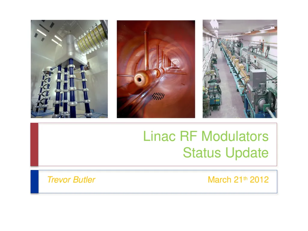
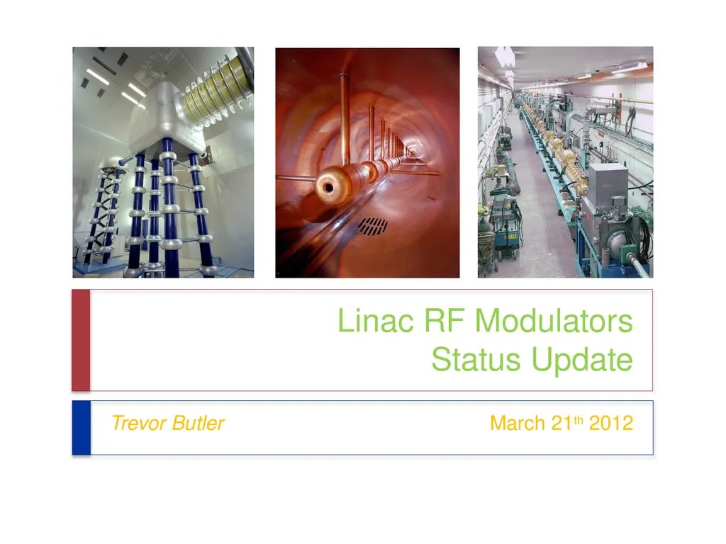
Linac RF Modulators
Status Update Trevor Butler March 21th 2012<br>
02
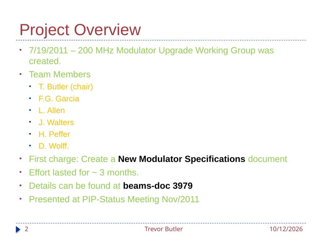
Project Overview 7/19/2011 – 200 MHz Modulator Upgrade Working Group was created.
Team Members
T. Butler (chair)
F.G. Garcia
L. Allen
J. Walters
H. Peffer
D. Wolff.
First charge: Create a New Modulator Specifications document
Effort lasted for ~ 3 months.
Details can be found at beams-doc 3979
Presented at PIP-Status Meeting Nov/2011 3/20/2012 Trevor Butler 2<br>
Team Members
T. Butler (chair)
F.G. Garcia
L. Allen
J. Walters
H. Peffer
D. Wolff.
First charge: Create a New Modulator Specifications document
Effort lasted for ~ 3 months.
Details can be found at beams-doc 3979
Presented at PIP-Status Meeting Nov/2011 3/20/2012 Trevor Butler 2<br>
03
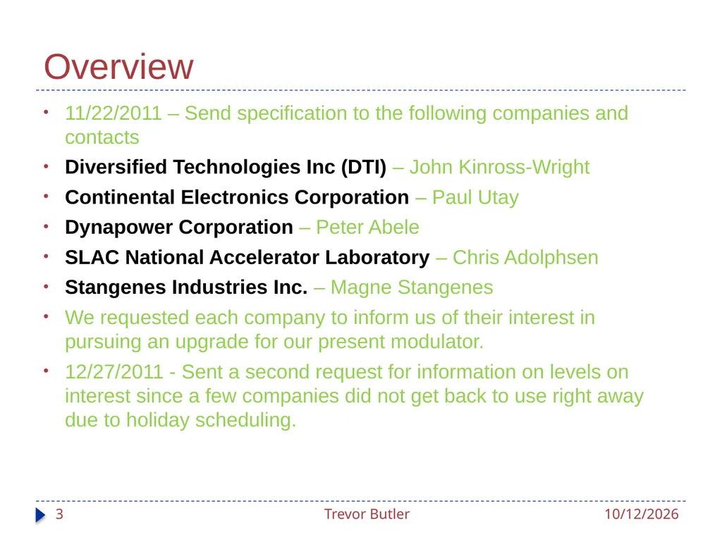
Overview 11/22/2011 – Send specification to the following companies and contacts
Diversified Technologies Inc (DTI) – John Kinross-Wright
Continental Electronics Corporation – Paul Utay
Dynapower Corporation – Peter Abele
SLAC National Accelerator Laboratory – Chris Adolphsen
Stangenes Industries Inc. – Magne Stangenes
We requested each company to inform us of their interest in pursuing an upgrade for our present modulator.
12/27/2011 - Sent a second request for information on levels on interest since a few companies did not get back to use right away due to holiday scheduling. 3/20/2012 Trevor Butler 3<br>
Diversified Technologies Inc (DTI) – John Kinross-Wright
Continental Electronics Corporation – Paul Utay
Dynapower Corporation – Peter Abele
SLAC National Accelerator Laboratory – Chris Adolphsen
Stangenes Industries Inc. – Magne Stangenes
We requested each company to inform us of their interest in pursuing an upgrade for our present modulator.
12/27/2011 - Sent a second request for information on levels on interest since a few companies did not get back to use right away due to holiday scheduling. 3/20/2012 Trevor Butler 3<br>
04
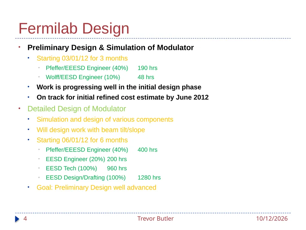
Fermilab Design Preliminary Design & Simulation of Modulator
Starting 03/01/12 for 3 months
Pfeffer/EEESD Engineer (40%) 190 hrs
Wolff/EESD Engineer (10%) 48 hrs
Work is progressing well in the initial design phase
On track for initial refined cost estimate by June 2012
Detailed Design of Modulator
Simulation and design of various components
Will design work with beam tilt/slope
Starting 06/01/12 for 6 months
Pfeffer/EEESD Engineer (40%) 400 hrs
EESD Engineer (20%) 200 hrs
EESD Tech (100%) 960 hrs
EESD Design/Drafting (100%) 1280 hrs
Goal: Preliminary Design well advanced 3/20/2012 Trevor Butler 4<br>
Starting 03/01/12 for 3 months
Pfeffer/EEESD Engineer (40%) 190 hrs
Wolff/EESD Engineer (10%) 48 hrs
Work is progressing well in the initial design phase
On track for initial refined cost estimate by June 2012
Detailed Design of Modulator
Simulation and design of various components
Will design work with beam tilt/slope
Starting 06/01/12 for 6 months
Pfeffer/EEESD Engineer (40%) 400 hrs
EESD Engineer (20%) 200 hrs
EESD Tech (100%) 960 hrs
EESD Design/Drafting (100%) 1280 hrs
Goal: Preliminary Design well advanced 3/20/2012 Trevor Butler 4<br>
05
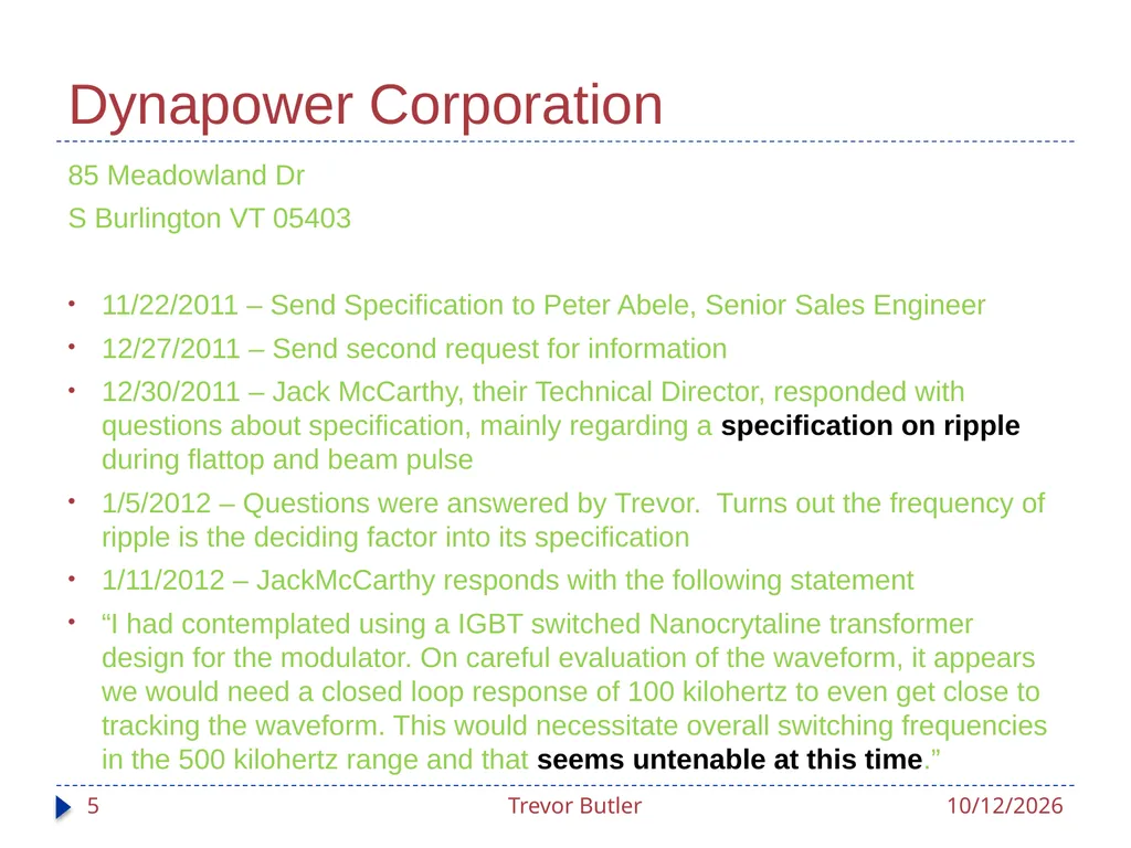
Dynapower Corporation 85 Meadowland Dr
S Burlington VT 05403
11/22/2011 – Send Specification to Peter Abele, Senior Sales Engineer
12/27/2011 – Send second request for information
12/30/2011 – Jack McCarthy, their Technical Director, responded with questions about specification, mainly regarding a specification on ripple during flattop and beam pulse
1/5/2012 – Questions were answered by Trevor. Turns out the frequency of ripple is the deciding factor into its specification
1/11/2012 – JackMcCarthy responds with the following statement
“I had contemplated using a IGBT switched Nanocrytaline transformer design for the modulator. On careful evaluation of the waveform, it appears we would need a closed loop response of 100 kilohertz to even get close to tracking the waveform. This would necessitate overall switching frequencies in the 500 kilohertz range and that seems untenable at this time.” 3/20/2012 Trevor Butler 5<br>
S Burlington VT 05403
11/22/2011 – Send Specification to Peter Abele, Senior Sales Engineer
12/27/2011 – Send second request for information
12/30/2011 – Jack McCarthy, their Technical Director, responded with questions about specification, mainly regarding a specification on ripple during flattop and beam pulse
1/5/2012 – Questions were answered by Trevor. Turns out the frequency of ripple is the deciding factor into its specification
1/11/2012 – JackMcCarthy responds with the following statement
“I had contemplated using a IGBT switched Nanocrytaline transformer design for the modulator. On careful evaluation of the waveform, it appears we would need a closed loop response of 100 kilohertz to even get close to tracking the waveform. This would necessitate overall switching frequencies in the 500 kilohertz range and that seems untenable at this time.” 3/20/2012 Trevor Butler 5<br>
06
Stangenes Industries Inc. 1052 East Meadow Circle
Palo Alto, CA 94303-4271
11/22/2011 – Send Specification to Magne Stangenes – President
12/14/2011 – Response by Randy Ross that they have decided to no-bid our request for two reasons
They believe to meet the modulator specifications; it will require the use of a hard tube modulator similar to your existing design. They do not have the expertise nor are planning on going into hard tube modulator design or support.
They evaluated the possibilities of using their in-house solid state Marx modulator system to meet our requirements, but several requirements tend to negate the applicability. These include the requirement for an adjustable Peak Voltage Time, an adjustable Beam Top Tilt, and the concern about the applicability of using solid state switches to drive a load that will likely have 200 MHz RF coming back down to the modulator. 3/20/2012 Trevor Butler 6<br>
Palo Alto, CA 94303-4271
11/22/2011 – Send Specification to Magne Stangenes – President
12/14/2011 – Response by Randy Ross that they have decided to no-bid our request for two reasons
They believe to meet the modulator specifications; it will require the use of a hard tube modulator similar to your existing design. They do not have the expertise nor are planning on going into hard tube modulator design or support.
They evaluated the possibilities of using their in-house solid state Marx modulator system to meet our requirements, but several requirements tend to negate the applicability. These include the requirement for an adjustable Peak Voltage Time, an adjustable Beam Top Tilt, and the concern about the applicability of using solid state switches to drive a load that will likely have 200 MHz RF coming back down to the modulator. 3/20/2012 Trevor Butler 6<br>
07
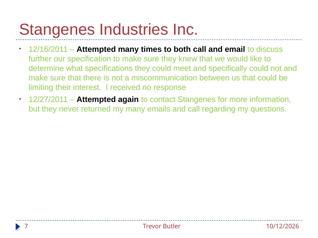
Stangenes Industries Inc. 12/16/2011 – Attempted many times to both call and email to discuss further our specification to make sure they knew that we would like to determine what specifications they could meet and specifically could not and make sure that there is not a miscommunication between us that could be limiting their interest. I received no response
12/27/2011 – Attempted again to contact Stangenes for more information, but they never returned my many emails and call regarding my questions. 3/20/2012 Trevor Butler 7<br>
12/27/2011 – Attempted again to contact Stangenes for more information, but they never returned my many emails and call regarding my questions. 3/20/2012 Trevor Butler 7<br>
08
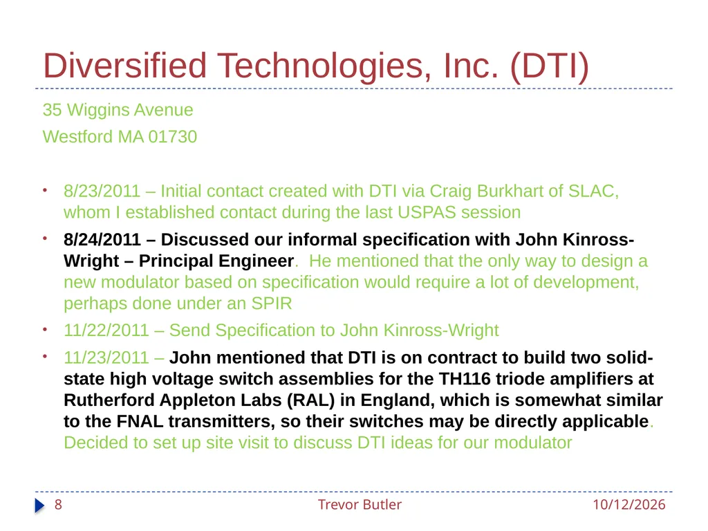
Diversified Technologies, Inc. (DTI) 35 Wiggins Avenue
Westford MA 01730
8/23/2011 – Initial contact created with DTI via Craig Burkhart of SLAC, whom I established contact during the last USPAS session
8/24/2011 – Discussed our informal specification with John Kinross-Wright – Principal Engineer. He mentioned that the only way to design a new modulator based on specification would require a lot of development, perhaps done under an SPIR
11/22/2011 – Send Specification to John Kinross-Wright
11/23/2011 – John mentioned that DTI is on contract to build two solid-state high voltage switch assemblies for the TH116 triode amplifiers at Rutherford Appleton Labs (RAL) in England, which is somewhat similar to the FNAL transmitters, so their switches may be directly applicable. Decided to set up site visit to discuss DTI ideas for our modulator 3/20/2012 Trevor Butler 8<br>
Westford MA 01730
8/23/2011 – Initial contact created with DTI via Craig Burkhart of SLAC, whom I established contact during the last USPAS session
8/24/2011 – Discussed our informal specification with John Kinross-Wright – Principal Engineer. He mentioned that the only way to design a new modulator based on specification would require a lot of development, perhaps done under an SPIR
11/22/2011 – Send Specification to John Kinross-Wright
11/23/2011 – John mentioned that DTI is on contract to build two solid-state high voltage switch assemblies for the TH116 triode amplifiers at Rutherford Appleton Labs (RAL) in England, which is somewhat similar to the FNAL transmitters, so their switches may be directly applicable. Decided to set up site visit to discuss DTI ideas for our modulator 3/20/2012 Trevor Butler 8<br>
09
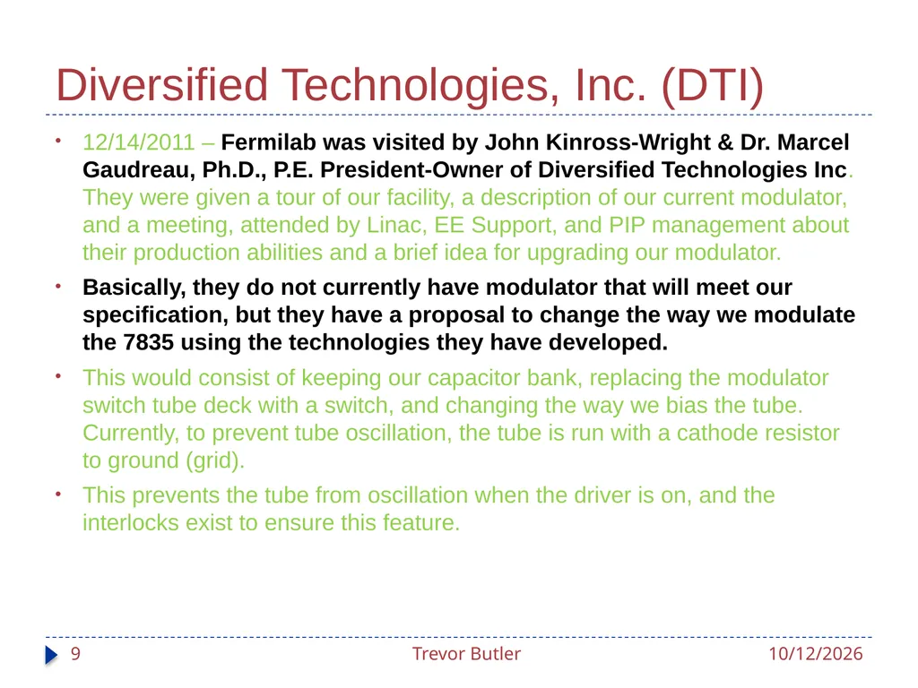
Diversified Technologies, Inc. (DTI) 12/14/2011 – Fermilab was visited by John Kinross-Wright & Dr. Marcel Gaudreau, Ph.D., P.E. President-Owner of Diversified Technologies Inc. They were given a tour of our facility, a description of our current modulator, and a meeting, attended by Linac, EE Support, and PIP management about their production abilities and a brief idea for upgrading our modulator.
Basically, they do not currently have modulator that will meet our specification, but they have a proposal to change the way we modulate the 7835 using the technologies they have developed.
This would consist of keeping our capacitor bank, replacing the modulator switch tube deck with a switch, and changing the way we bias the tube. Currently, to prevent tube oscillation, the tube is run with a cathode resistor to ground (grid).
This prevents the tube from oscillation when the driver is on, and the interlocks exist to ensure this feature. 3/20/2012 Trevor Butler 9<br>
Basically, they do not currently have modulator that will meet our specification, but they have a proposal to change the way we modulate the 7835 using the technologies they have developed.
This would consist of keeping our capacitor bank, replacing the modulator switch tube deck with a switch, and changing the way we bias the tube. Currently, to prevent tube oscillation, the tube is run with a cathode resistor to ground (grid).
This prevents the tube from oscillation when the driver is on, and the interlocks exist to ensure this feature. 3/20/2012 Trevor Butler 9<br>
10
Diversified Technologies, Inc. (DTI) Instead, DTI suggests that we change the 7835 bias circuitry, which if it works, would be a novel way to regulate the gradient of the cavity.
Unfortunately, this has never been done before and we don’t even know if it will work, let alone, be stable for operations and have not effect on tube lifetime, or even tube life.
The early papers about the modulator describe this concern and state that it was the reason that they had to build the modulator as it currently is.
3/1/2012 – Contacted DTI about their plans for this test. DTI said they will provide us which their circuit design to test this idea on an old 7835 on test stand LRF7
DTI Suggested at least these initial 3 tests to start the process
Make the current modulator look like a switch (maybe possible?)
Run the Driver with a “notch” in the middle of the pulse to replicate driver modulator and determine the lowest gradient before oscillation.
Work with their engineering team on a contract basis to build circuitry to modulate the cathode of the tube to do cathode biasing.
Relay all information of tests to Photonis (7835 PA manufacturer) for review. 3/20/2012 Trevor Butler 10<br>
Unfortunately, this has never been done before and we don’t even know if it will work, let alone, be stable for operations and have not effect on tube lifetime, or even tube life.
The early papers about the modulator describe this concern and state that it was the reason that they had to build the modulator as it currently is.
3/1/2012 – Contacted DTI about their plans for this test. DTI said they will provide us which their circuit design to test this idea on an old 7835 on test stand LRF7
DTI Suggested at least these initial 3 tests to start the process
Make the current modulator look like a switch (maybe possible?)
Run the Driver with a “notch” in the middle of the pulse to replicate driver modulator and determine the lowest gradient before oscillation.
Work with their engineering team on a contract basis to build circuitry to modulate the cathode of the tube to do cathode biasing.
Relay all information of tests to Photonis (7835 PA manufacturer) for review. 3/20/2012 Trevor Butler 10<br>
11
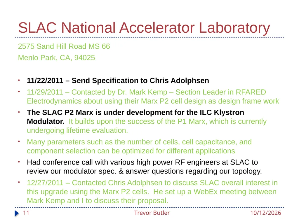
SLAC National Accelerator Laboratory 2575 Sand Hill Road MS 66
Menlo Park, CA, 94025
11/22/2011 – Send Specification to Chris Adolphsen
11/29/2011 – Contacted by Dr. Mark Kemp – Section Leader in RFARED Electrodynamics about using their Marx P2 cell design as design frame work
The SLAC P2 Marx is under development for the ILC Klystron Modulator. It builds upon the success of the P1 Marx, which is currently undergoing lifetime evaluation.
Many parameters such as the number of cells, cell capacitance, and component selection can be optimized for different applications
Had conference call with various high power RF engineers at SLAC to review our modulator spec. & answer questions regarding our topology.
12/27/2011 – Contacted Chris Adolphsen to discuss SLAC overall interest in this upgrade using the Marx P2 cells. He set up a WebEx meeting between Mark Kemp and I to discuss their proposal. 3/20/2012 Trevor Butler 11<br>
Menlo Park, CA, 94025
11/22/2011 – Send Specification to Chris Adolphsen
11/29/2011 – Contacted by Dr. Mark Kemp – Section Leader in RFARED Electrodynamics about using their Marx P2 cell design as design frame work
The SLAC P2 Marx is under development for the ILC Klystron Modulator. It builds upon the success of the P1 Marx, which is currently undergoing lifetime evaluation.
Many parameters such as the number of cells, cell capacitance, and component selection can be optimized for different applications
Had conference call with various high power RF engineers at SLAC to review our modulator spec. & answer questions regarding our topology.
12/27/2011 – Contacted Chris Adolphsen to discuss SLAC overall interest in this upgrade using the Marx P2 cells. He set up a WebEx meeting between Mark Kemp and I to discuss their proposal. 3/20/2012 Trevor Butler 11<br>
12
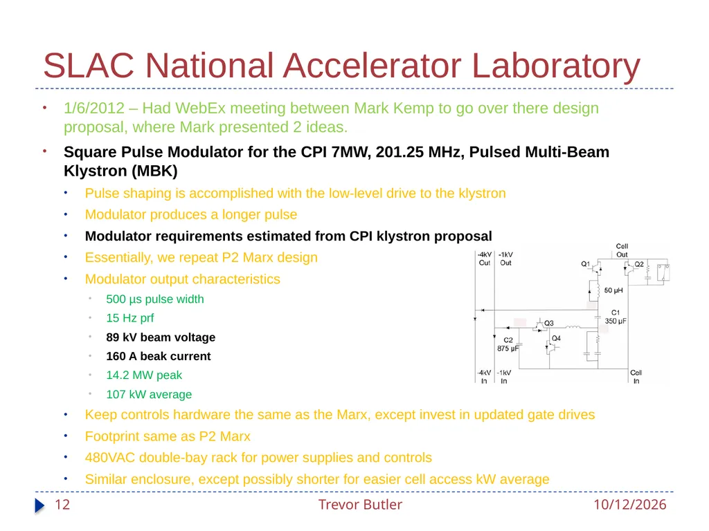
SLAC National Accelerator Laboratory 1/6/2012 – Had WebEx meeting between Mark Kemp to go over there design proposal, where Mark presented 2 ideas.
Square Pulse Modulator for the CPI 7MW, 201.25 MHz, Pulsed Multi-Beam Klystron (MBK)
Pulse shaping is accomplished with the low-level drive to the klystron
Modulator produces a longer pulse
Modulator requirements estimated from CPI klystron proposal
Essentially, we repeat P2 Marx design
Modulator output characteristics
500 µs pulse width
15 Hz prf
89 kV beam voltage
160 A beak current
14.2 MW peak
107 kW average
Keep controls hardware the same as the Marx, except invest in updated gate drives
Footprint same as P2 Marx
480VAC double-bay rack for power supplies and controls
Similar enclosure, except possibly shorter for easier cell access kW average 3/20/2012 Trevor Butler 12<br>
Square Pulse Modulator for the CPI 7MW, 201.25 MHz, Pulsed Multi-Beam Klystron (MBK)
Pulse shaping is accomplished with the low-level drive to the klystron
Modulator produces a longer pulse
Modulator requirements estimated from CPI klystron proposal
Essentially, we repeat P2 Marx design
Modulator output characteristics
500 µs pulse width
15 Hz prf
89 kV beam voltage
160 A beak current
14.2 MW peak
107 kW average
Keep controls hardware the same as the Marx, except invest in updated gate drives
Footprint same as P2 Marx
480VAC double-bay rack for power supplies and controls
Similar enclosure, except possibly shorter for easier cell access kW average 3/20/2012 Trevor Butler 12<br>
13
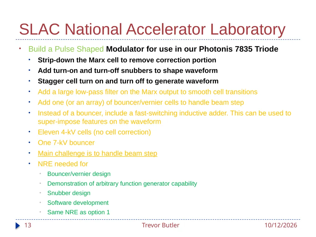
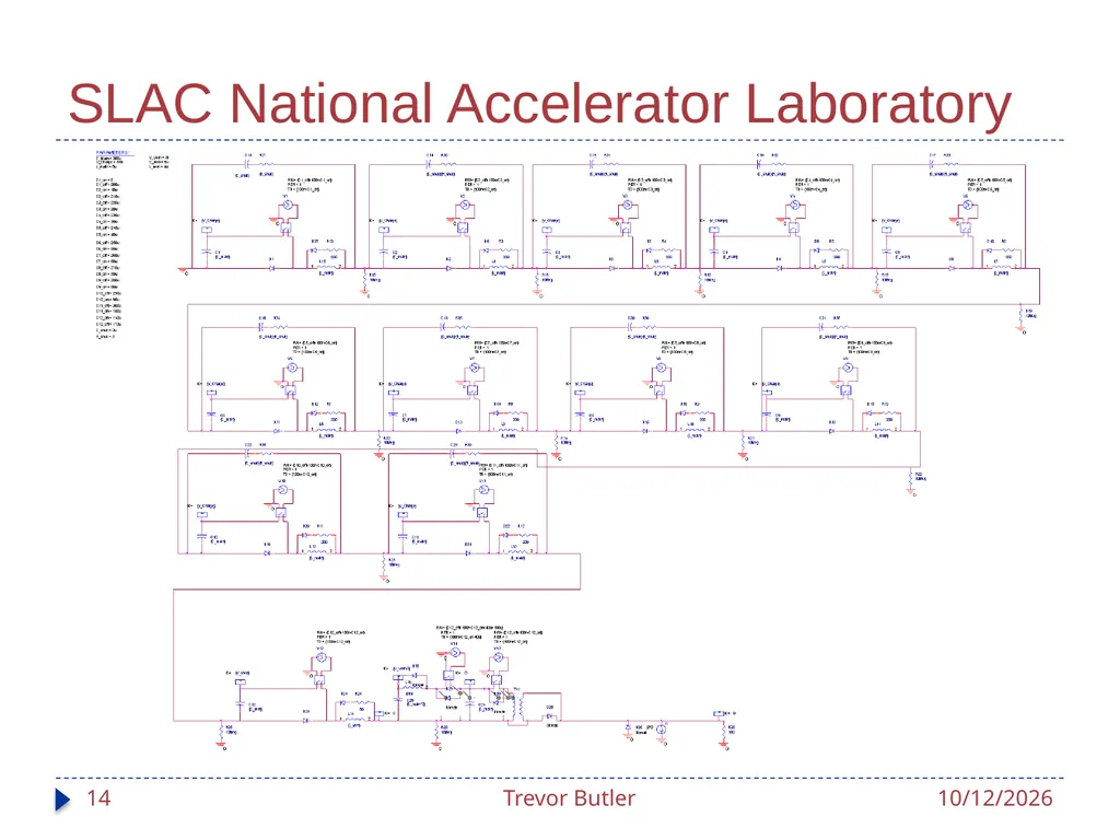
SLAC National Accelerator Laboratory Build a Pulse Shaped Modulator for use in our Photonis 7835 Triode
Strip-down the Marx cell to remove correction portion
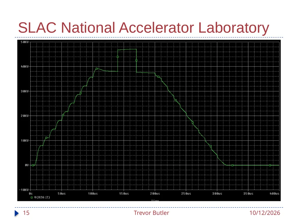
Add turn-on and turn-off snubbers to shape waveform
Stagger cell turn on and turn off to generate waveform
Add a large low-pass filter on the Marx output to smooth cell transitions
Add one (or an array) of bouncer/vernier cells to handle beam step
Instead of a bouncer, include a fast-switching inductive adder. This can be used to super-impose features on the waveform
Eleven 4-kV cells (no cell correction)
One 7-kV bouncer
Main challenge is to handle beam step
NRE needed for
Bouncer/vernier design
Demonstration of arbitrary function generator capability
Snubber design
Software development
Same NRE as option 1 3/20/2012 Trevor Butler 13<br>
Strip-down the Marx cell to remove correction portion
Add turn-on and turn-off snubbers to shape waveform
Stagger cell turn on and turn off to generate waveform
Add a large low-pass filter on the Marx output to smooth cell transitions
Add one (or an array) of bouncer/vernier cells to handle beam step
Instead of a bouncer, include a fast-switching inductive adder. This can be used to super-impose features on the waveform
Eleven 4-kV cells (no cell correction)
One 7-kV bouncer
Main challenge is to handle beam step
NRE needed for
Bouncer/vernier design
Demonstration of arbitrary function generator capability
Snubber design
Software development
Same NRE as option 1 3/20/2012 Trevor Butler 13<br>
14
SLAC National Accelerator Laboratory 3/20/2012 Trevor Butler 14<br>
15
SLAC National Accelerator Laboratory 3/20/2012 Trevor Butler 15<br>
16
SLAC National Accelerator Laboratory 1/5/2012 – Had WebEx meeting between Mark Kemp and Fermilab to go over their design proposal, where Mark presented 2 ideas.
1/11/2012 - Had meeting with Dan & Howie to discuss SLAC modulator initial design scoping and create questions to ask back to SLAC
Main Questions
Rise and Fall time control
Flat Top regulation
Running the cavity up in gradient from 0-100%
Inputs and Outputs required
System Size
System Cost
1/13/2012 – Had another meeting with Mark Kemp to discuss these questions. To fully answer these questions, SLAC would need some time to develop a better model and study each question. To do this, it was suggested that we created a Memorandum Purchase Order to start the 2 months of engineering time required to answer our questions. 3/20/2012 Trevor Butler 16<br>
1/11/2012 - Had meeting with Dan & Howie to discuss SLAC modulator initial design scoping and create questions to ask back to SLAC
Main Questions
Rise and Fall time control
Flat Top regulation
Running the cavity up in gradient from 0-100%
Inputs and Outputs required
System Size
System Cost
1/13/2012 – Had another meeting with Mark Kemp to discuss these questions. To fully answer these questions, SLAC would need some time to develop a better model and study each question. To do this, it was suggested that we created a Memorandum Purchase Order to start the 2 months of engineering time required to answer our questions. 3/20/2012 Trevor Butler 16<br>
17
SLAC Scope of Work Work with Fermi to hone-in critical, desired, and unimportant portions of the output waveform. Refine modulator circuit model to appropriately accommodate needs. Produce initial design of the vernier circuit. (4 man-weeks) Deliverable: Circuit model results with waveforms demonstrating parameters of interest2
Develop controls block diagram appropriately detailed to answer questions of how the regulation loop may be accomplished. (2 man-weeks) Deliverable: Block diagram with hardware preferences and required future development described.
Develop detailed cost estimate with schedule, major component choices, and component quotes. (1 man-week) Deliverable: "Vetted" cost and schedule estimate for entire system
Produce footprint of modulator along with utility needs (1 man-week) Deliverable: Floor plan and rough system electrical interconnect drawing
Presentation to Fermilab at the conclusion of this work to answer questions about how this system would integrate at FNAL, with the goal of having this work done by August 1, 2012 3/20/2012 Trevor Butler 17<br>
Develop controls block diagram appropriately detailed to answer questions of how the regulation loop may be accomplished. (2 man-weeks) Deliverable: Block diagram with hardware preferences and required future development described.
Develop detailed cost estimate with schedule, major component choices, and component quotes. (1 man-week) Deliverable: "Vetted" cost and schedule estimate for entire system
Produce footprint of modulator along with utility needs (1 man-week) Deliverable: Floor plan and rough system electrical interconnect drawing
Presentation to Fermilab at the conclusion of this work to answer questions about how this system would integrate at FNAL, with the goal of having this work done by August 1, 2012 3/20/2012 Trevor Butler 17<br>
18
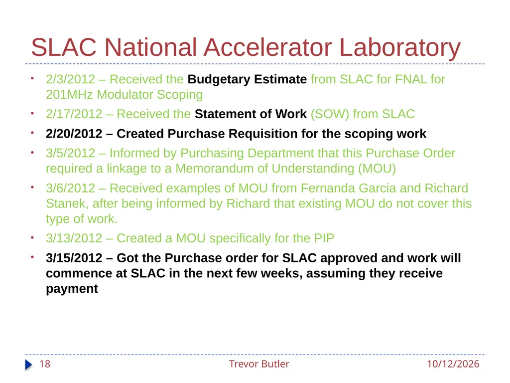
SLAC National Accelerator Laboratory 2/3/2012 – Received the Budgetary Estimate from SLAC for FNAL for 201MHz Modulator Scoping
2/17/2012 – Received the Statement of Work (SOW) from SLAC
2/20/2012 – Created Purchase Requisition for the scoping work
3/5/2012 – Informed by Purchasing Department that this Purchase Order required a linkage to a Memorandum of Understanding (MOU)
3/6/2012 – Received examples of MOU from Fernanda Garcia and Richard Stanek, after being informed by Richard that existing MOU do not cover this type of work.
3/13/2012 – Created a MOU specifically for the PIP
3/15/2012 – Got the Purchase order for SLAC approved and work will commence at SLAC in the next few weeks, assuming they receive payment 3/20/2012 Trevor Butler 18<br>
2/17/2012 – Received the Statement of Work (SOW) from SLAC
2/20/2012 – Created Purchase Requisition for the scoping work
3/5/2012 – Informed by Purchasing Department that this Purchase Order required a linkage to a Memorandum of Understanding (MOU)
3/6/2012 – Received examples of MOU from Fernanda Garcia and Richard Stanek, after being informed by Richard that existing MOU do not cover this type of work.
3/13/2012 – Created a MOU specifically for the PIP
3/15/2012 – Got the Purchase order for SLAC approved and work will commence at SLAC in the next few weeks, assuming they receive payment 3/20/2012 Trevor Butler 18<br>
19
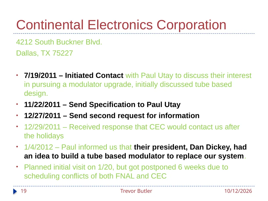
Continental Electronics Corporation 4212 South Buckner Blvd.
Dallas, TX 75227
7/19/2011 – Initiated Contact with Paul Utay to discuss their interest in pursuing a modulator upgrade, initially discussed tube based design.
11/22/2011 – Send Specification to Paul Utay
12/27/2011 – Send second request for information
12/29/2011 – Received response that CEC would contact us after the holidays
1/4/2012 – Paul informed us that their president, Dan Dickey, had an idea to build a tube based modulator to replace our system.
Planned initial visit on 1/20, but got postponed 6 weeks due to scheduling conflicts of both FNAL and CEC 3/20/2012 Trevor Butler 19<br>
Dallas, TX 75227
7/19/2011 – Initiated Contact with Paul Utay to discuss their interest in pursuing a modulator upgrade, initially discussed tube based design.
11/22/2011 – Send Specification to Paul Utay
12/27/2011 – Send second request for information
12/29/2011 – Received response that CEC would contact us after the holidays
1/4/2012 – Paul informed us that their president, Dan Dickey, had an idea to build a tube based modulator to replace our system.
Planned initial visit on 1/20, but got postponed 6 weeks due to scheduling conflicts of both FNAL and CEC 3/20/2012 Trevor Butler 19<br>
20
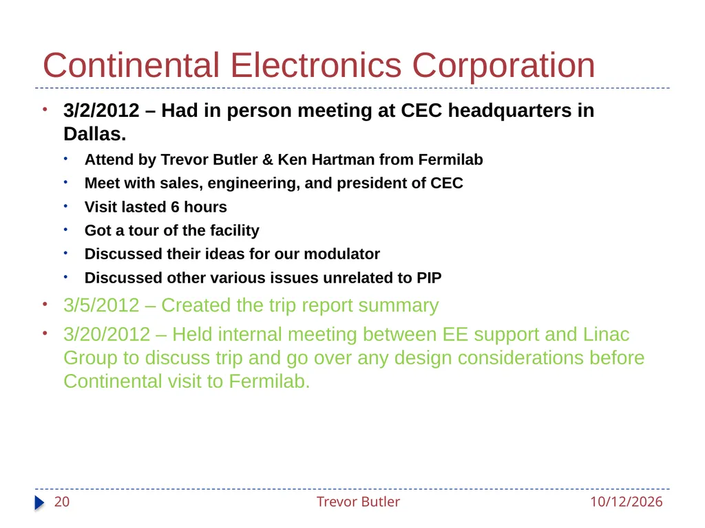
Continental Electronics Corporation 3/2/2012 – Had in person meeting at CEC headquarters in Dallas.
Attend by Trevor Butler & Ken Hartman from Fermilab
Meet with sales, engineering, and president of CEC
Visit lasted 6 hours
Got a tour of the facility
Discussed their ideas for our modulator
Discussed other various issues unrelated to PIP
3/5/2012 – Created the trip report summary
3/20/2012 – Held internal meeting between EE support and Linac Group to discuss trip and go over any design considerations before Continental visit to Fermilab. 3/20/2012 Trevor Butler 20<br>
Attend by Trevor Butler & Ken Hartman from Fermilab
Meet with sales, engineering, and president of CEC
Visit lasted 6 hours
Got a tour of the facility
Discussed their ideas for our modulator
Discussed other various issues unrelated to PIP
3/5/2012 – Created the trip report summary
3/20/2012 – Held internal meeting between EE support and Linac Group to discuss trip and go over any design considerations before Continental visit to Fermilab. 3/20/2012 Trevor Butler 20<br>
21
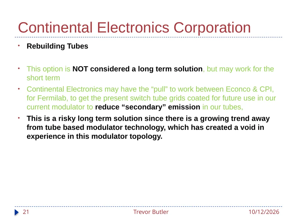
Continental Electronics Corporation Rebuilding Tubes
This option is NOT considered a long term solution, but may work for the short term
Continental Electronics may have the “pull” to work between Econco & CPI, for Fermilab, to get the present switch tube grids coated for future use in our current modulator to reduce “secondary” emission in our tubes,
This is a risky long term solution since there is a growing trend away from tube based modulator technology, which has created a void in experience in this modulator topology. 3/20/2012 Trevor Butler 21<br>
This option is NOT considered a long term solution, but may work for the short term
Continental Electronics may have the “pull” to work between Econco & CPI, for Fermilab, to get the present switch tube grids coated for future use in our current modulator to reduce “secondary” emission in our tubes,
This is a risky long term solution since there is a growing trend away from tube based modulator technology, which has created a void in experience in this modulator topology. 3/20/2012 Trevor Butler 21<br>
22
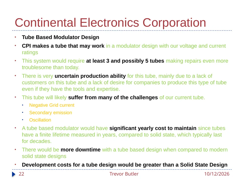
Continental Electronics Corporation Tube Based Modulator Design
CPI makes a tube that may work in a modulator design with our voltage and current ratings
This system would require at least 3 and possibly 5 tubes making repairs even more troublesome than today.
There is very uncertain production ability for this tube, mainly due to a lack of customers on this tube and a lack of desire for companies to produce this type of tube even if they have the tools and expertise.
This tube will likely suffer from many of the challenges of our current tube.
Negative Grid current
Secondary emission
Oscillation
A tube based modulator would have significant yearly cost to maintain since tubes have a finite lifetime measured in years, compared to solid state, which typically last for decades.
There would be more downtime with a tube based design when compared to modern solid state designs
Development costs for a tube design would be greater than a Solid State Design 3/20/2012 Trevor Butler 22<br>
CPI makes a tube that may work in a modulator design with our voltage and current ratings
This system would require at least 3 and possibly 5 tubes making repairs even more troublesome than today.
There is very uncertain production ability for this tube, mainly due to a lack of customers on this tube and a lack of desire for companies to produce this type of tube even if they have the tools and expertise.
This tube will likely suffer from many of the challenges of our current tube.
Negative Grid current
Secondary emission
Oscillation
A tube based modulator would have significant yearly cost to maintain since tubes have a finite lifetime measured in years, compared to solid state, which typically last for decades.
There would be more downtime with a tube based design when compared to modern solid state designs
Development costs for a tube design would be greater than a Solid State Design 3/20/2012 Trevor Butler 22<br>
23
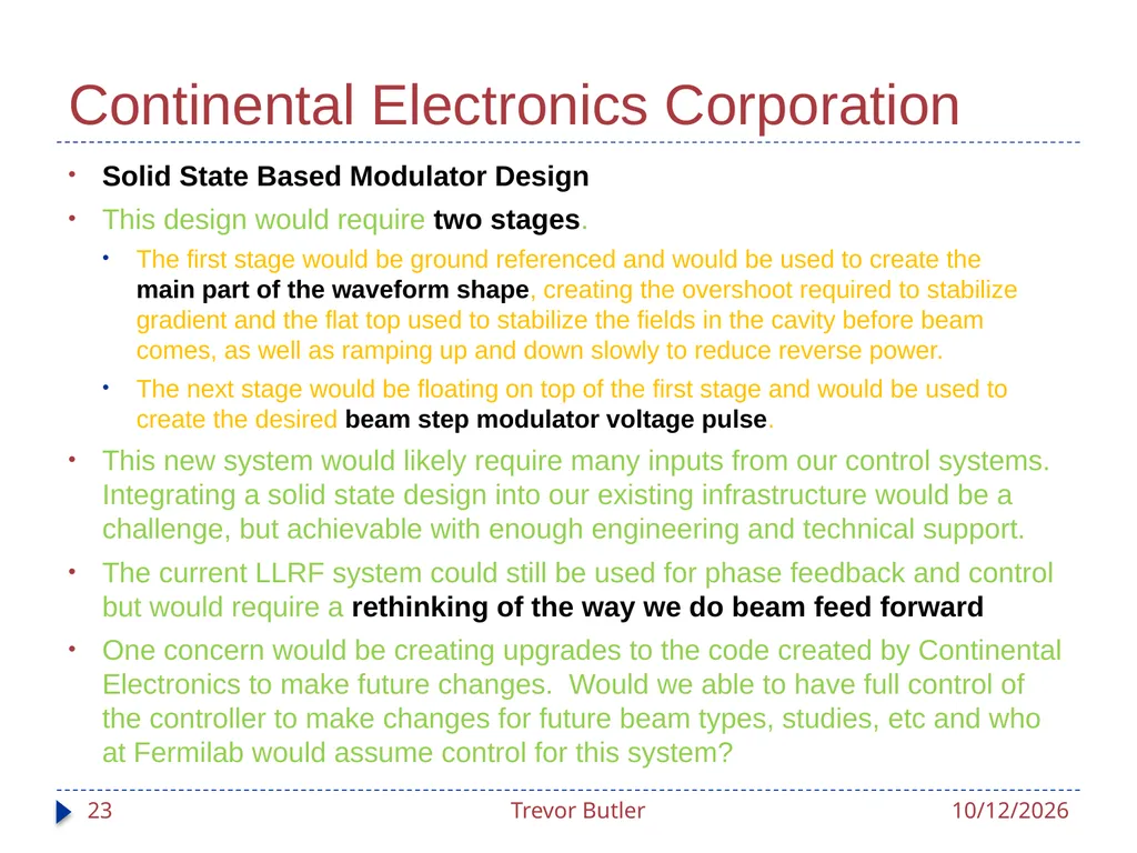
Continental Electronics Corporation Solid State Based Modulator Design
This design would require two stages.
The first stage would be ground referenced and would be used to create the main part of the waveform shape, creating the overshoot required to stabilize gradient and the flat top used to stabilize the fields in the cavity before beam comes, as well as ramping up and down slowly to reduce reverse power.
The next stage would be floating on top of the first stage and would be used to create the desired beam step modulator voltage pulse.
This new system would likely require many inputs from our control systems. Integrating a solid state design into our existing infrastructure would be a challenge, but achievable with enough engineering and technical support.
The current LLRF system could still be used for phase feedback and control but would require a rethinking of the way we do beam feed forward
One concern would be creating upgrades to the code created by Continental Electronics to make future changes. Would we able to have full control of the controller to make changes for future beam types, studies, etc and who at Fermilab would assume control for this system? 3/20/2012 Trevor Butler 23<br>
This design would require two stages.
The first stage would be ground referenced and would be used to create the main part of the waveform shape, creating the overshoot required to stabilize gradient and the flat top used to stabilize the fields in the cavity before beam comes, as well as ramping up and down slowly to reduce reverse power.
The next stage would be floating on top of the first stage and would be used to create the desired beam step modulator voltage pulse.
This new system would likely require many inputs from our control systems. Integrating a solid state design into our existing infrastructure would be a challenge, but achievable with enough engineering and technical support.
The current LLRF system could still be used for phase feedback and control but would require a rethinking of the way we do beam feed forward
One concern would be creating upgrades to the code created by Continental Electronics to make future changes. Would we able to have full control of the controller to make changes for future beam types, studies, etc and who at Fermilab would assume control for this system? 3/20/2012 Trevor Butler 23<br>
24
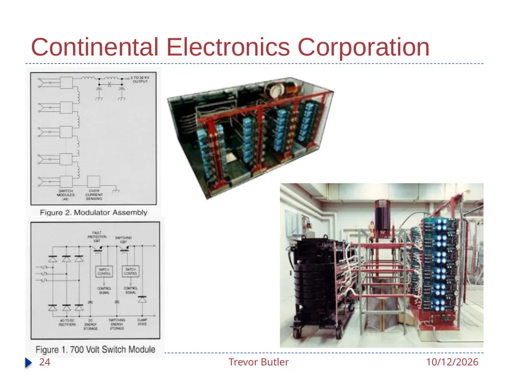
Continental Electronics Corporation 3/20/2012 Trevor Butler 24<br>
25
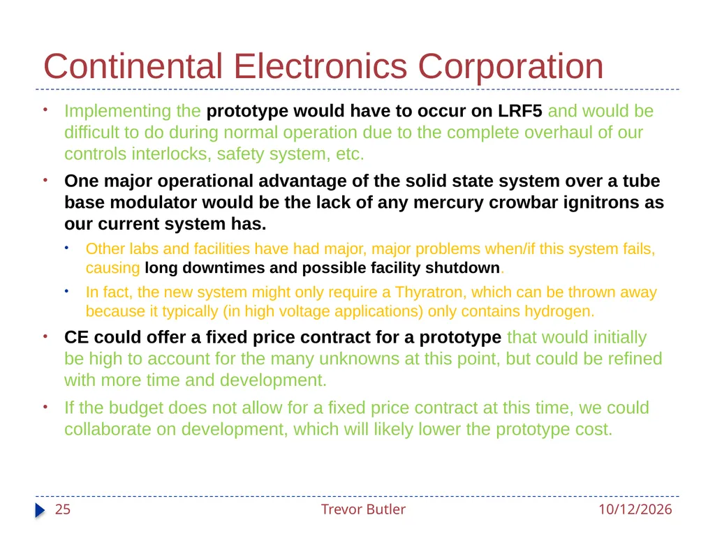
Continental Electronics Corporation Implementing the prototype would have to occur on LRF5 and would be difficult to do during normal operation due to the complete overhaul of our controls interlocks, safety system, etc.
One major operational advantage of the solid state system over a tube base modulator would be the lack of any mercury crowbar ignitrons as our current system has.
Other labs and facilities have had major, major problems when/if this system fails, causing long downtimes and possible facility shutdown.
In fact, the new system might only require a Thyratron, which can be thrown away because it typically (in high voltage applications) only contains hydrogen.
CE could offer a fixed price contract for a prototype that would initially be high to account for the many unknowns at this point, but could be refined with more time and development.
If the budget does not allow for a fixed price contract at this time, we could collaborate on development, which will likely lower the prototype cost. 3/20/2012 Trevor Butler 25<br>
One major operational advantage of the solid state system over a tube base modulator would be the lack of any mercury crowbar ignitrons as our current system has.
Other labs and facilities have had major, major problems when/if this system fails, causing long downtimes and possible facility shutdown.
In fact, the new system might only require a Thyratron, which can be thrown away because it typically (in high voltage applications) only contains hydrogen.
CE could offer a fixed price contract for a prototype that would initially be high to account for the many unknowns at this point, but could be refined with more time and development.
If the budget does not allow for a fixed price contract at this time, we could collaborate on development, which will likely lower the prototype cost. 3/20/2012 Trevor Butler 25<br>
26
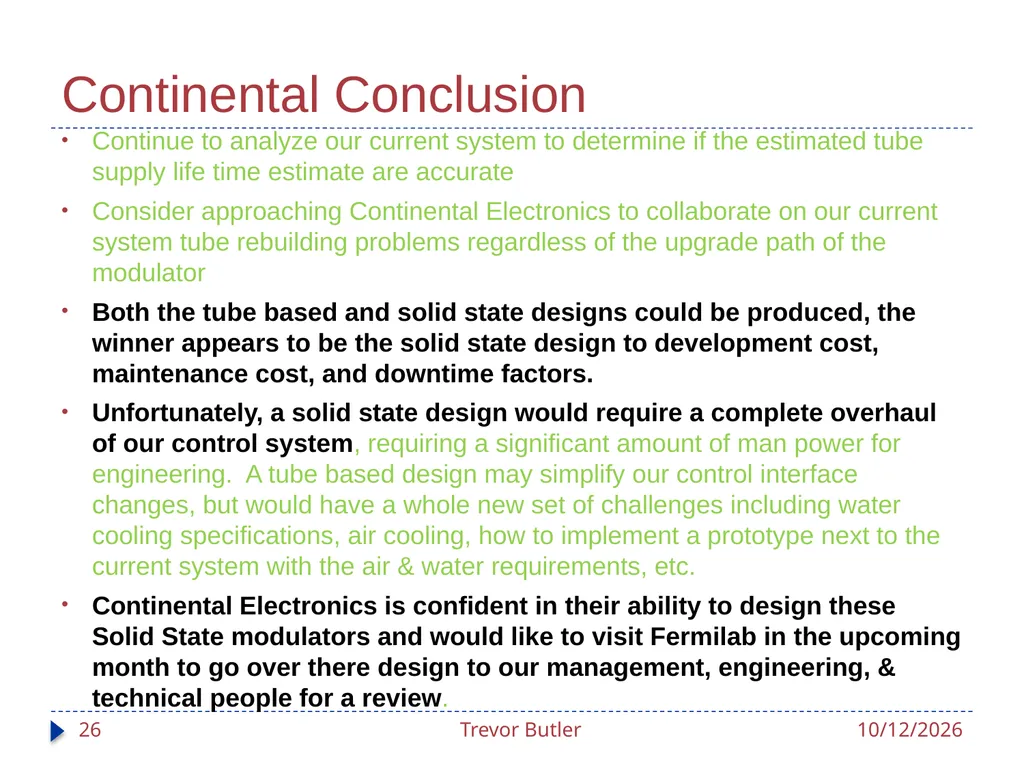
Continental Conclusion Continue to analyze our current system to determine if the estimated tube supply life time estimate are accurate
Consider approaching Continental Electronics to collaborate on our current system tube rebuilding problems regardless of the upgrade path of the modulator
Both the tube based and solid state designs could be produced, the winner appears to be the solid state design to development cost, maintenance cost, and downtime factors.
Unfortunately, a solid state design would require a complete overhaul of our control system, requiring a significant amount of man power for engineering. A tube based design may simplify our control interface changes, but would have a whole new set of challenges including water cooling specifications, air cooling, how to implement a prototype next to the current system with the air & water requirements, etc.
Continental Electronics is confident in their ability to design these Solid State modulators and would like to visit Fermilab in the upcoming month to go over there design to our management, engineering, & technical people for a review. 3/20/2012 Trevor Butler 26<br>
Consider approaching Continental Electronics to collaborate on our current system tube rebuilding problems regardless of the upgrade path of the modulator
Both the tube based and solid state designs could be produced, the winner appears to be the solid state design to development cost, maintenance cost, and downtime factors.
Unfortunately, a solid state design would require a complete overhaul of our control system, requiring a significant amount of man power for engineering. A tube based design may simplify our control interface changes, but would have a whole new set of challenges including water cooling specifications, air cooling, how to implement a prototype next to the current system with the air & water requirements, etc.
Continental Electronics is confident in their ability to design these Solid State modulators and would like to visit Fermilab in the upcoming month to go over there design to our management, engineering, & technical people for a review. 3/20/2012 Trevor Butler 26<br>
27
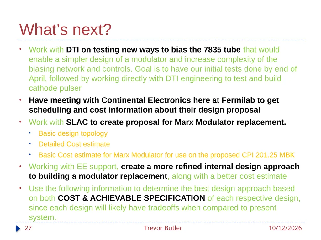
What’s next? Work with DTI on testing new ways to bias the 7835 tube that would enable a simpler design of a modulator and increase complexity of the biasing network and controls. Goal is to have our initial tests done by end of April, followed by working directly with DTI engineering to test and build cathode pulser
Have meeting with Continental Electronics here at Fermilab to get scheduling and cost information about their design proposal
Work with SLAC to create proposal for Marx Modulator replacement.
Basic design topology
Detailed Cost estimate
Basic Cost estimate for Marx Modulator for use on the proposed CPI 201.25 MBK
Working with EE support, create a more refined internal design approach to building a modulator replacement, along with a better cost estimate
Use the following information to determine the best design approach based on both COST & ACHIEVABLE SPECIFICATION of each respective design, since each design will likely have tradeoffs when compared to present system. 3/20/2012 Trevor Butler 27<br>
Have meeting with Continental Electronics here at Fermilab to get scheduling and cost information about their design proposal
Work with SLAC to create proposal for Marx Modulator replacement.
Basic design topology
Detailed Cost estimate
Basic Cost estimate for Marx Modulator for use on the proposed CPI 201.25 MBK
Working with EE support, create a more refined internal design approach to building a modulator replacement, along with a better cost estimate
Use the following information to determine the best design approach based on both COST & ACHIEVABLE SPECIFICATION of each respective design, since each design will likely have tradeoffs when compared to present system. 3/20/2012 Trevor Butler 27<br>
28
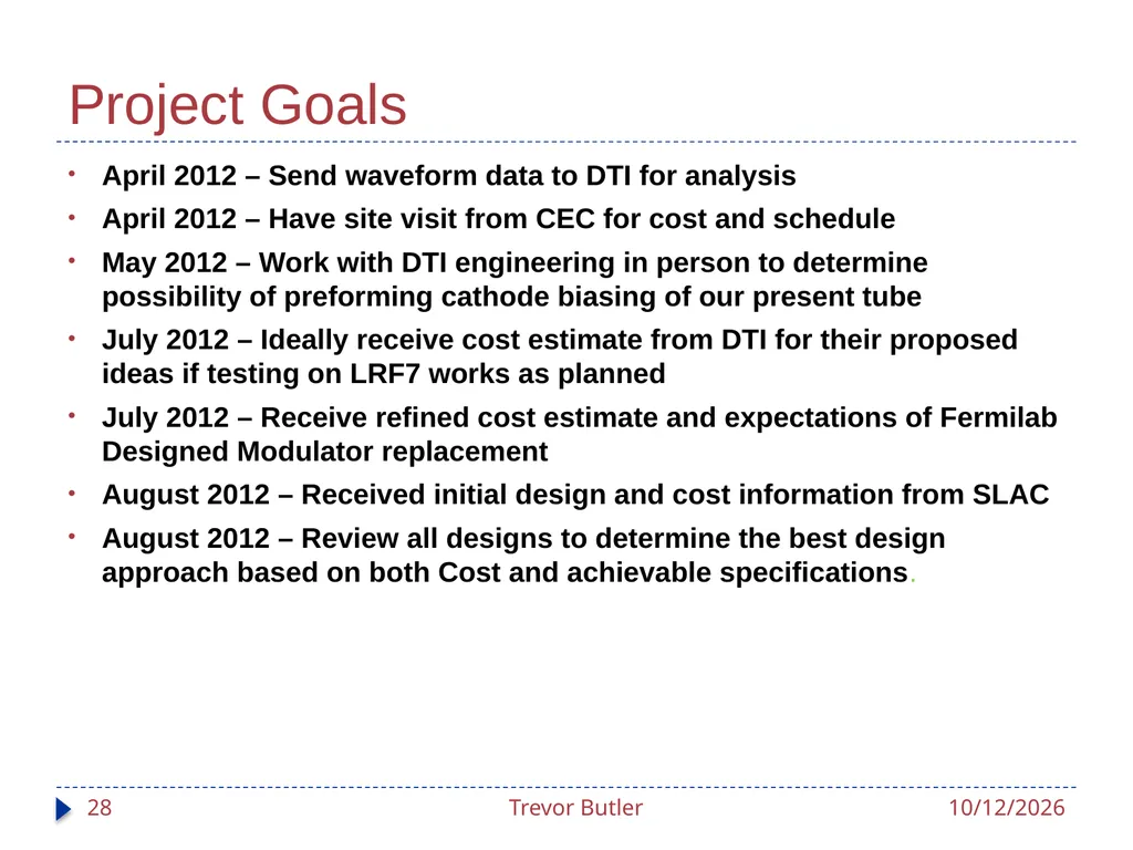
Project Goals April 2012 – Send waveform data to DTI for analysis
April 2012 – Have site visit from CEC for cost and schedule
May 2012 – Work with DTI engineering in person to determine possibility of preforming cathode biasing of our present tube
July 2012 – Ideally receive cost estimate from DTI for their proposed ideas if testing on LRF7 works as planned
July 2012 – Receive refined cost estimate and expectations of Fermilab Designed Modulator replacement
August 2012 – Received initial design and cost information from SLAC
August 2012 – Review all designs to determine the best design approach based on both Cost and achievable specifications. 3/20/2012 Trevor Butler 28<br>
April 2012 – Have site visit from CEC for cost and schedule
May 2012 – Work with DTI engineering in person to determine possibility of preforming cathode biasing of our present tube
July 2012 – Ideally receive cost estimate from DTI for their proposed ideas if testing on LRF7 works as planned
July 2012 – Receive refined cost estimate and expectations of Fermilab Designed Modulator replacement
August 2012 – Received initial design and cost information from SLAC
August 2012 – Review all designs to determine the best design approach based on both Cost and achievable specifications. 3/20/2012 Trevor Butler 28<br>