Periodic Steady State (PSS) Analysis P. Bruschi Microelectronic System Design 1 Useful to study several number of circuits driven by periodic, large-signal excitations. Some examples: RF circuits: oscillators, mixers, PLL... Power
"Periodic Steady State (PSS) Analysis P. Bruschi –" is the property of its rightful owner. Permission is granted to
download and print the materials on this website for personal, non-commercial use only, and to display it
on your personal computer provided you do not modify the materials and that you retain all copyright
notices contained in the materials. By downloading content from our website, you accept the terms of this
agreement.
Presentation Transcript
01
Periodic Steady State (PSS) Analysis P. Bruschi – Microelectronic System Design 1 Useful to study several number of circuits driven by periodic, large-signal excitations. Some examples:
RF circuits: oscillators, mixers, PLL...
Power Electronics circuits: dc-dc converters, rectifiers...
Analog circuits: switched-capacitor amplifiers, chopper amplifiers… PSS is the equivalent of DC analysis but applied to periodic circuits: finds the periodic steady-state response of a circuit and evalutes the periodic operating point. The steady-state solution is then linearized for time-varying small-signal analysis as Periodic AC (PAC), Periodic Noise (PNOISE)…<br>
02
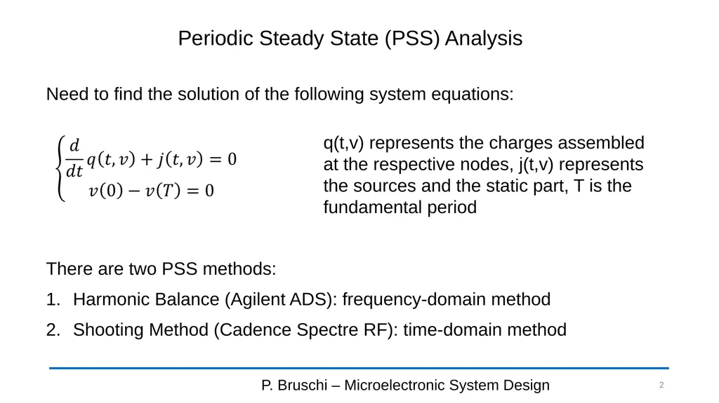
Periodic Steady State (PSS) Analysis P. Bruschi – Microelectronic System Design 2 Need to find the solution of the following system equations: q(t,v) represents the charges assembled at the respective nodes, j(t,v) represents the sources and the static part, T is the fundamental period There are two PSS methods:
Harmonic Balance (Agilent ADS): frequency-domain method
Shooting Method (Cadence Spectre RF): time-domain method<br>
03
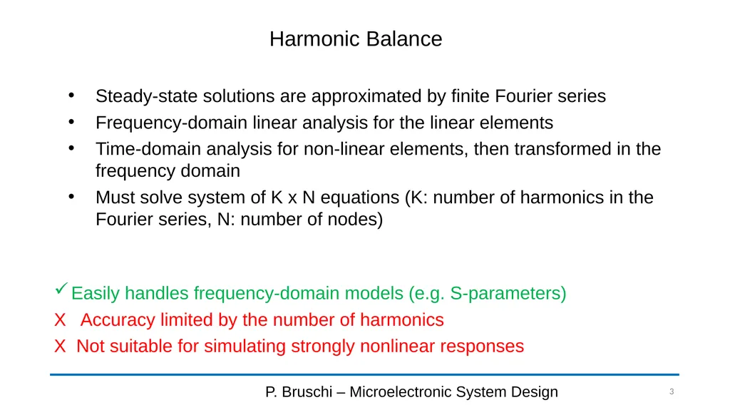
Harmonic Balance P. Bruschi – Microelectronic System Design 3 Steady-state solutions are approximated by finite Fourier series
Frequency-domain linear analysis for the linear elements
Time-domain analysis for non-linear elements, then transformed in the frequency domain
Must solve system of K x N equations (K: number of harmonics in the Fourier series, N: number of nodes) Easily handles frequency-domain models (e.g. S-parameters)
X Accuracy limited by the number of harmonics
X Not suitable for simulating strongly nonlinear responses<br>
04
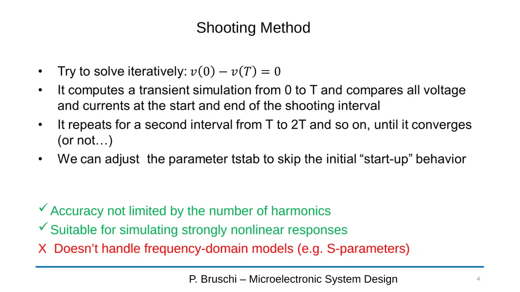
Shooting Method P. Bruschi – Microelectronic System Design 4 Accuracy not limited by the number of harmonics
Suitable for simulating strongly nonlinear responses
X Doesn’t handle frequency-domain models (e.g. S-parameters)<br>
05
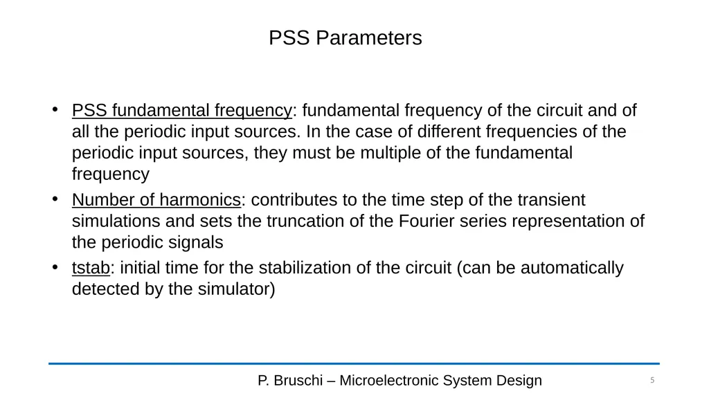
PSS Parameters P. Bruschi – Microelectronic System Design 5 PSS fundamental frequency: fundamental frequency of the circuit and of all the periodic input sources. In the case of different frequencies of the periodic input sources, they must be multiple of the fundamental frequency
Number of harmonics: contributes to the time step of the transient simulations and sets the truncation of the Fourier series representation of the periodic signals
tstab: initial time for the stabilization of the circuit (can be automatically detected by the simulator)<br>
06
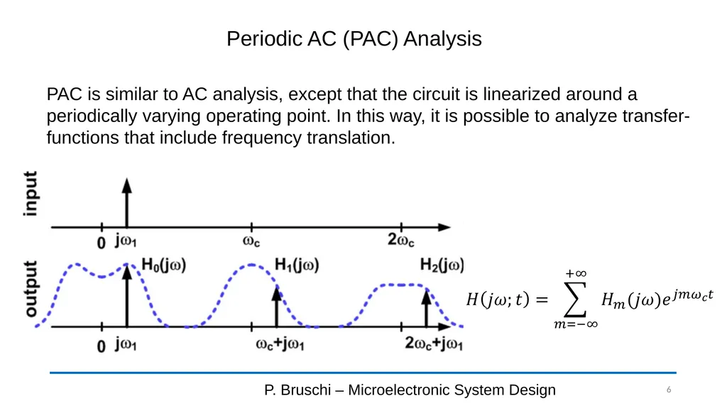
Periodic AC (PAC) Analysis P. Bruschi – Microelectronic System Design 6 PAC is similar to AC analysis, except that the circuit is linearized around a periodically varying operating point. In this way, it is possible to analyze transfer-functions that include frequency translation.<br>
07
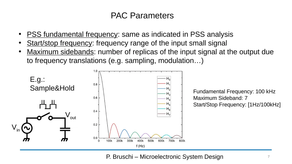
PAC Parameters P. Bruschi – Microelectronic System Design 7 PSS fundamental frequency: same as indicated in PSS analysis
Start/stop frequency: frequency range of the input small signal
Maximum sidebands: number of replicas of the input signal at the output due to frequency translations (e.g. sampling, modulation…) E.g.: Sample&Hold Fundamental Frequency: 100 kHz
Maximum Sideband: 7
Start/Stop Frequency: [1Hz/100kHz] Vout Vin<br>
08
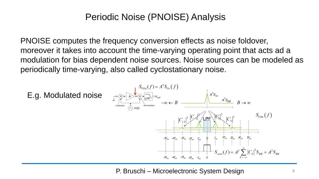
Periodic Noise (PNOISE) Analysis P. Bruschi – Microelectronic System Design 8 PNOISE computes the frequency conversion effects as noise foldover, moreover it takes into account the time-varying operating point that acts ad a modulation for bias dependent noise sources. Noise sources can be modeled as periodically time-varying, also called cyclostationary noise. E.g. Modulated noise<br>
09
PNOISE Parameters P. Bruschi – Microelectronic System Design 9 PSS fundamental frequency: same as indicated in PSS analysis
Start/stop frequency: frequency range of the noise spectral density
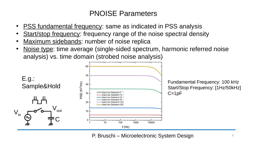
Maximum sidebands: number of noise replica
Noise type: time average (single-sided spectrum, harmonic referred noise analysis) vs. time domain (strobed noise analysis) E.g.: Sample&Hold Vout Vin Fundamental Frequency: 100 kHz
Start/Stop Frequency: [1Hz/50kHz]
C=1pF C<br>