04
Mechanical Advantage (MA) Ratio of the magnitude of the resistance and effort forces
Ratio of distance traveled by the effort and the resistance force
Calculated ratios allow designers to manipulate speed, distance, force, and function<br>
05
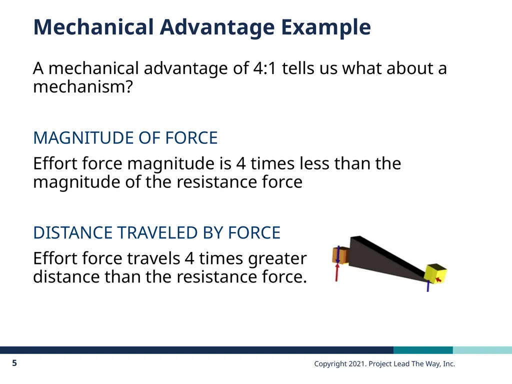
Mechanical Advantage Example A mechanical advantage of 4:1 tells us what about a mechanism?
MAGNITUDE OF FORCE
Effort force magnitude is 4 times less than the magnitude of the resistance force
DISTANCE TRAVELED BY FORCE
Effort force travels 4 times greater �distance than the resistance force.<br>
06
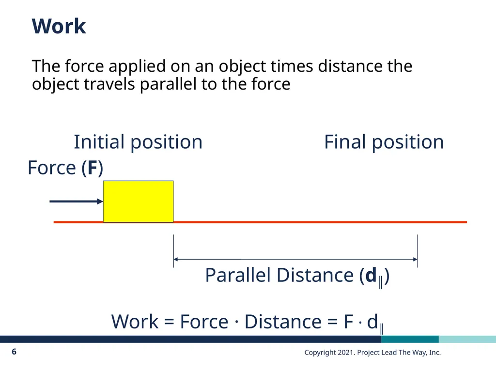
Work The force applied on an object times distance the object travels parallel to the force Initial position Final position Parallel Distance (d║) Work = Force · Distance = F · d║<br>
07
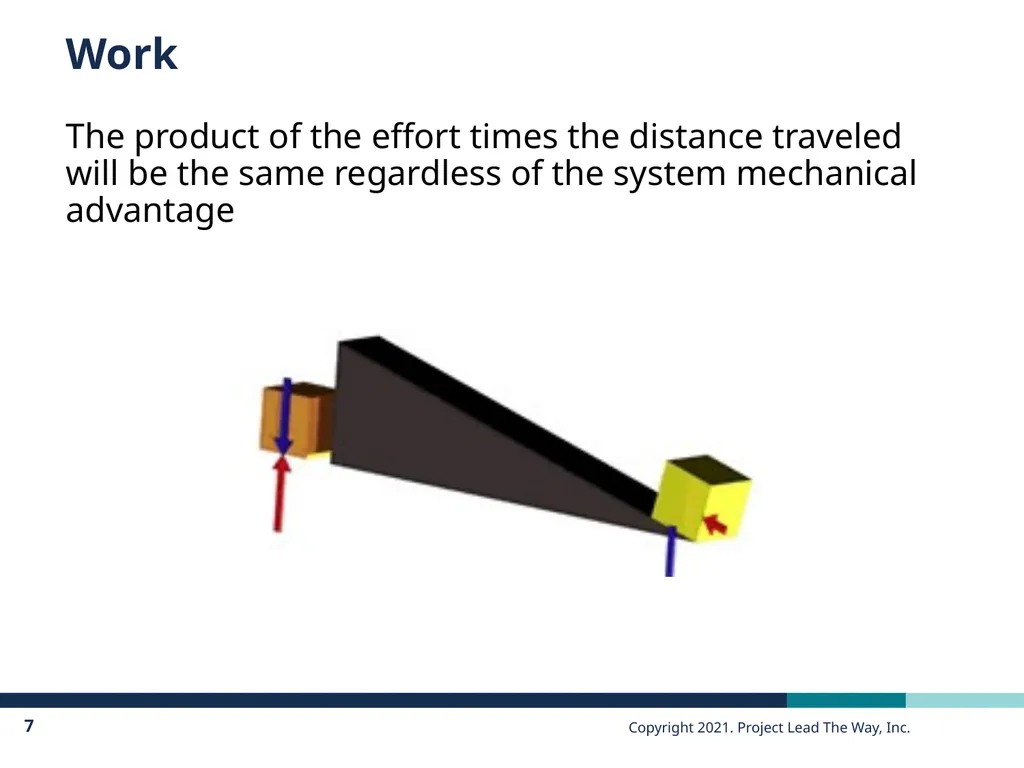
Work The product of the effort times the distance traveled will be the same regardless of the system mechanical advantage<br>
08
Mechanical Advantage Ratios One is the magic number
If MA is greater than 1:
Proportionally less effort force is required to overcome the resistance force
Proportionally greater effort distance is required to overcome the resistance force
If MA is less than 1:
Proportionally greater effort force is required to overcome the resistance force
Proportionally less effort distance is required to overcome the resistance force MA can never be less than or equal to zero.<br>
09
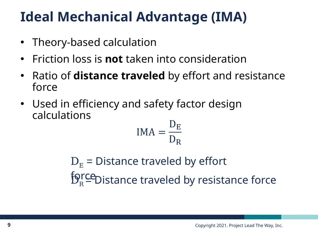
Ideal Mechanical Advantage (IMA) Theory-based calculation
Friction loss is not taken into consideration
Ratio of distance traveled by effort and resistance force
Used in efficiency and safety factor design calculations DR = Distance traveled by resistance force DE = Distance traveled by effort force<br>
10
Actual Mechanical Advantage (AMA) Inquiry-based calculation
Frictional losses are taken into consideration
Used in efficiency calculations
Ratio of force magnitudes FE = Magnitude of effort force FR = Magnitude of resistance force<br>
11
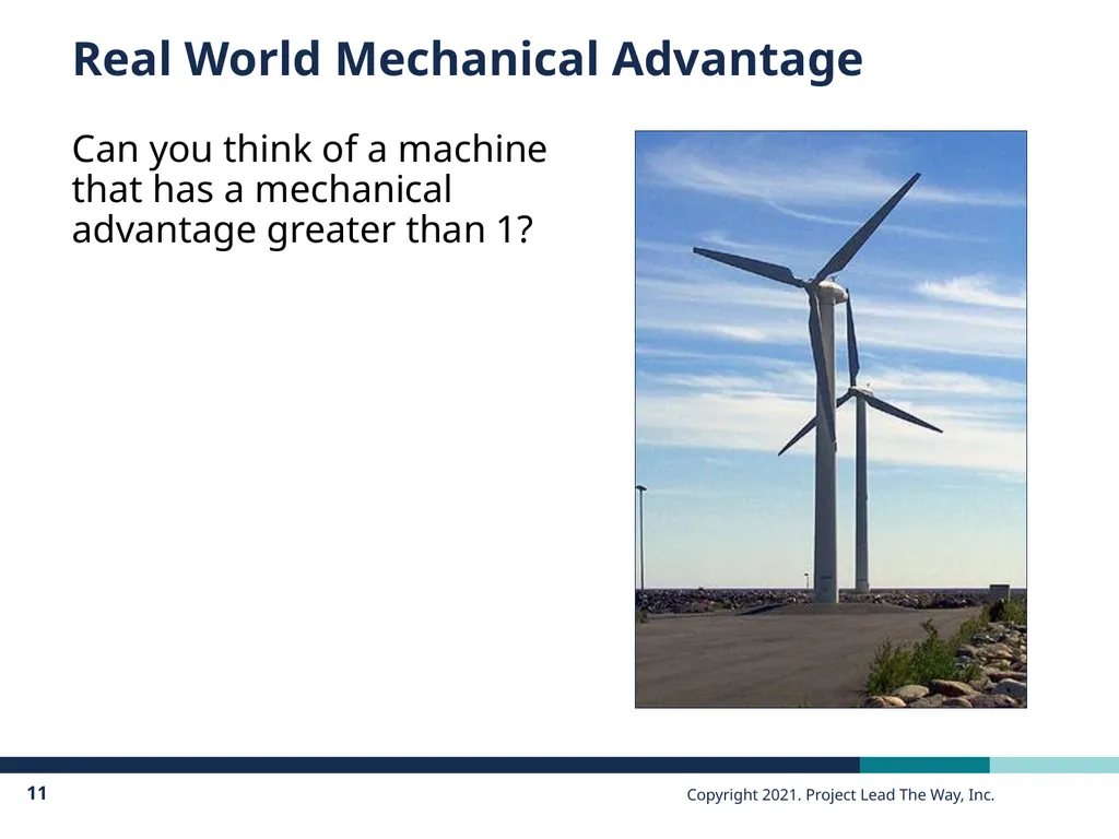
Real World Mechanical Advantage Can you think of a machine that has a mechanical advantage greater than 1?<br>
12
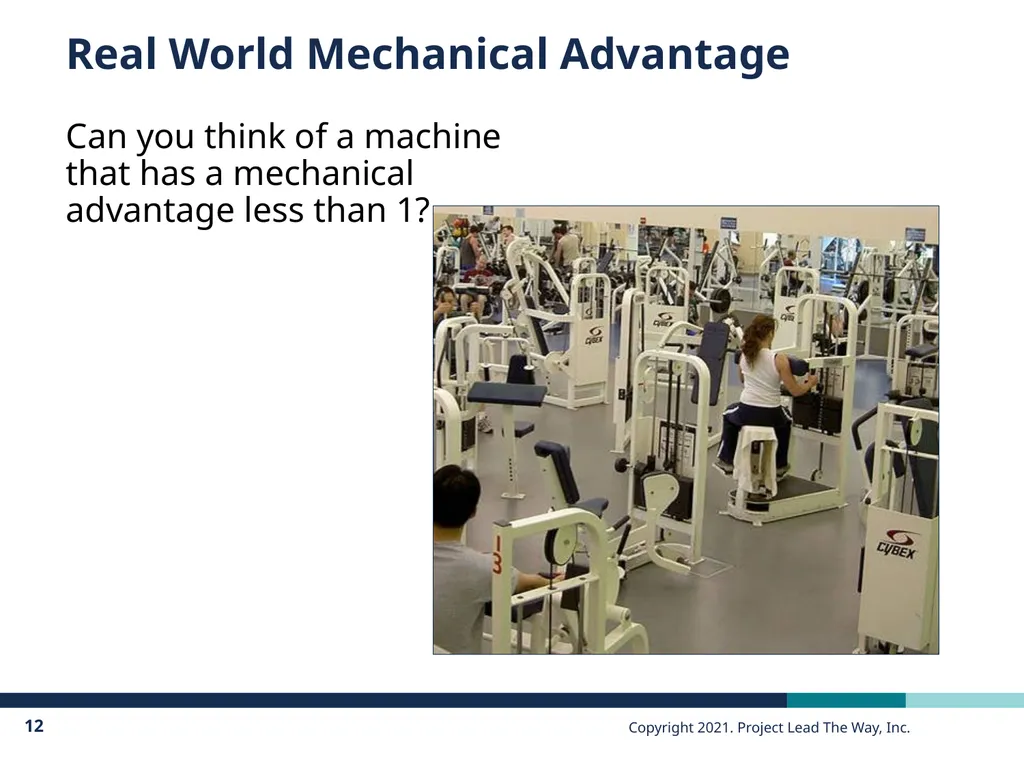
Real World Mechanical Advantage Can you think of a machine that has a mechanical advantage less than 1?<br>
13
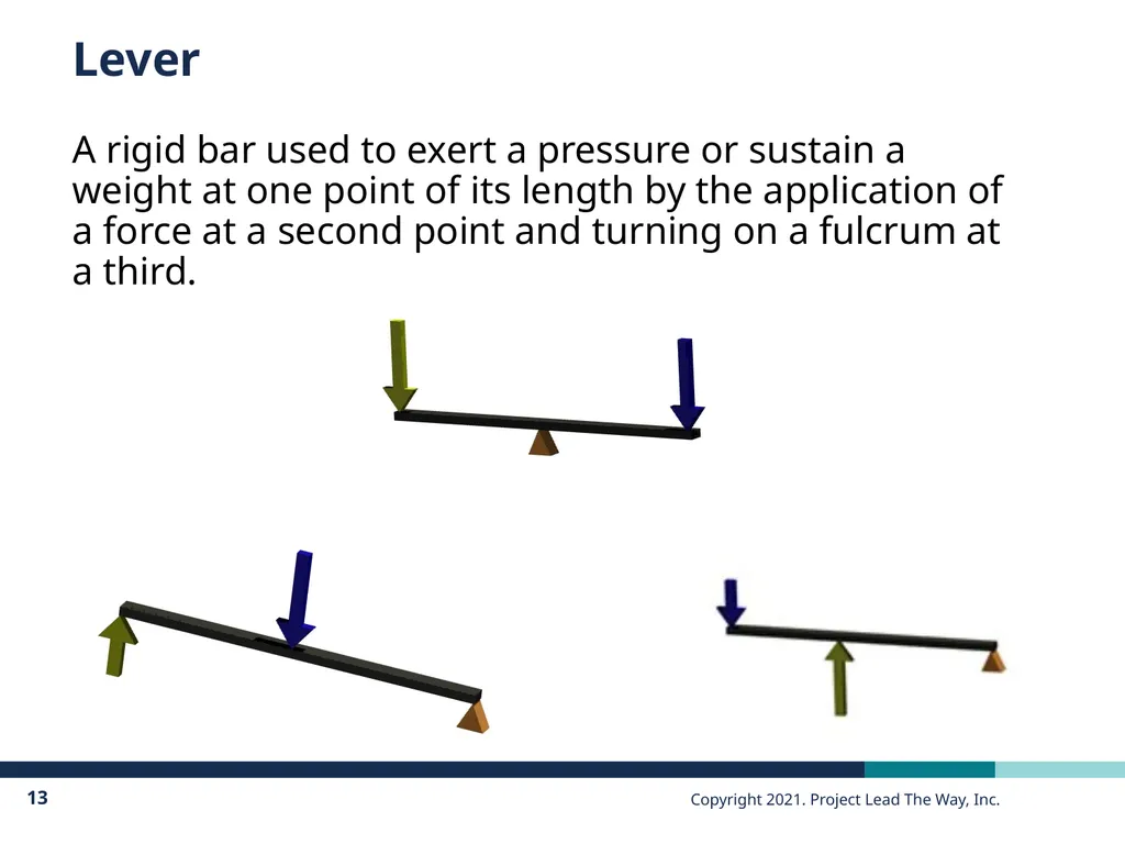
Lever A rigid bar used to exert a pressure or sustain a weight at one point of its length by the application of a force at a second point and turning on a fulcrum at a third.<br>
14
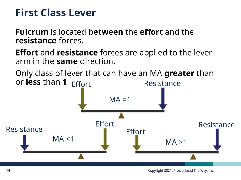
First Class Lever Fulcrum is located between the effort and the resistance forces.
Effort and resistance forces are applied to the lever arm in the same direction.
Only class of lever that can have an MA greater than or less than 1.<br>
15
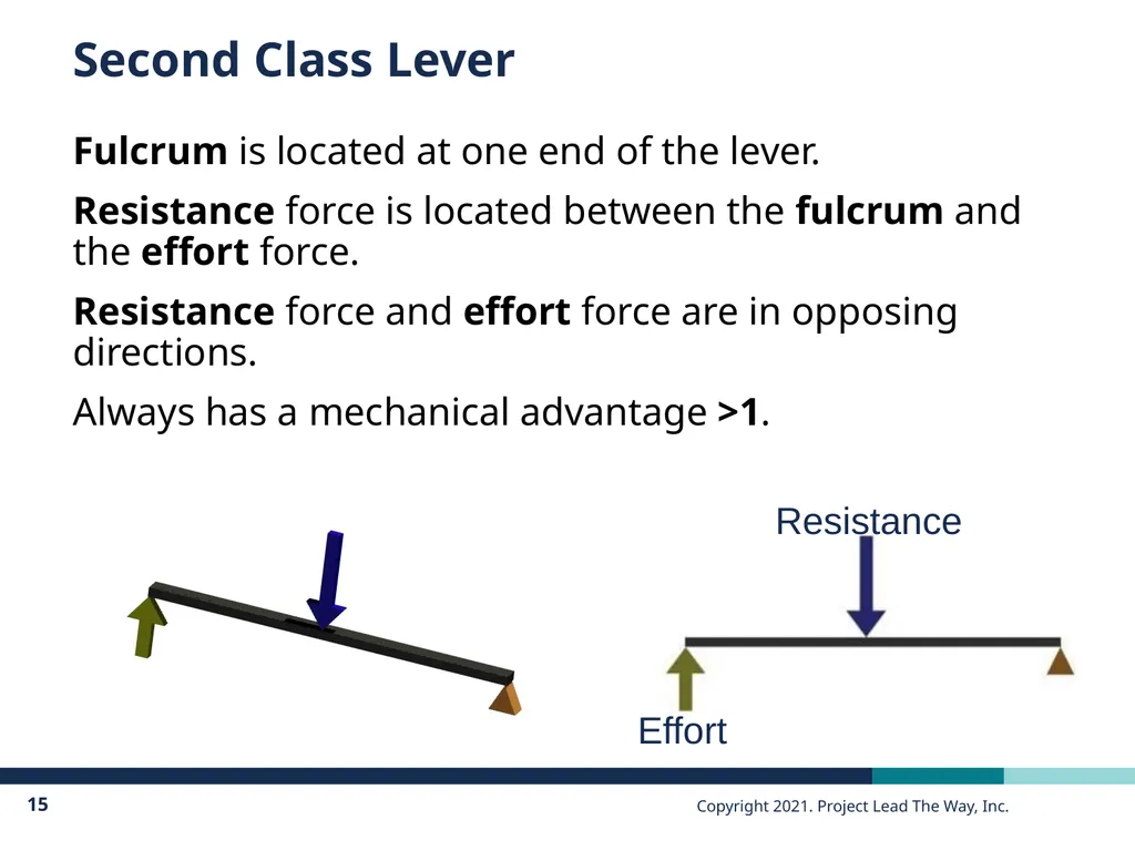
Second Class Lever Fulcrum is located at one end of the lever.
Resistance force is located between the fulcrum and the effort force.
Resistance force and effort force are in opposing directions.
Always has a mechanical advantage >1.<br>
16
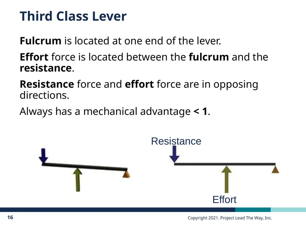
Third Class Lever Fulcrum is located at one end of the lever.
Effort force is located between the fulcrum and the resistance.
Resistance force and effort force are in opposing directions.
Always has a mechanical advantage < 1.<br>
17
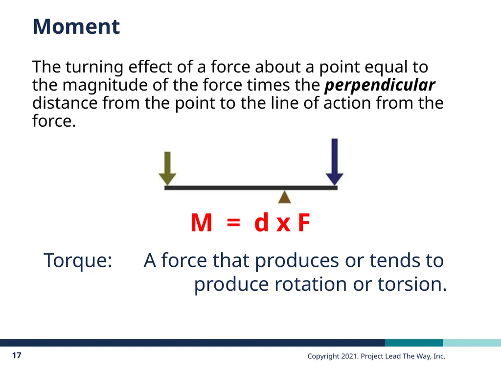
Moment The turning effect of a force about a point equal to the magnitude of the force times the perpendicular distance from the point to the line of action from the force. M = d x F Torque: A force that produces or tends to produce rotation or torsion.<br>
18
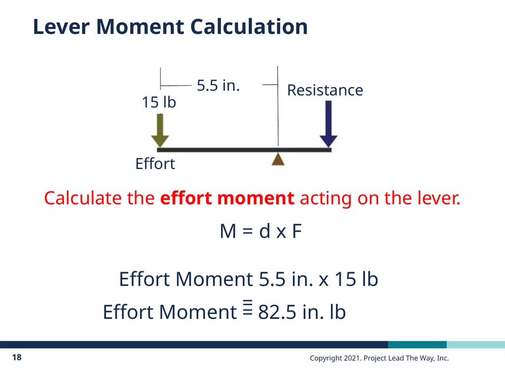
Lever Moment Calculation 15 lbs M = d x F 5.5 in. Calculate the effort moment acting on the lever. Effort Moment = Effort Moment = 5.5 in. x 15 lb 82.5 in. lb 15 lb<br>
19
Lever Moment Calculation When the sum of all moments on a lever equals 0, the lever is in rotational equilibrium.
Rotational Equilibrium
The state in which the sum of all the clockwise moments equals the sum of all the counterclockwise moments about a pivot point.<br>
20
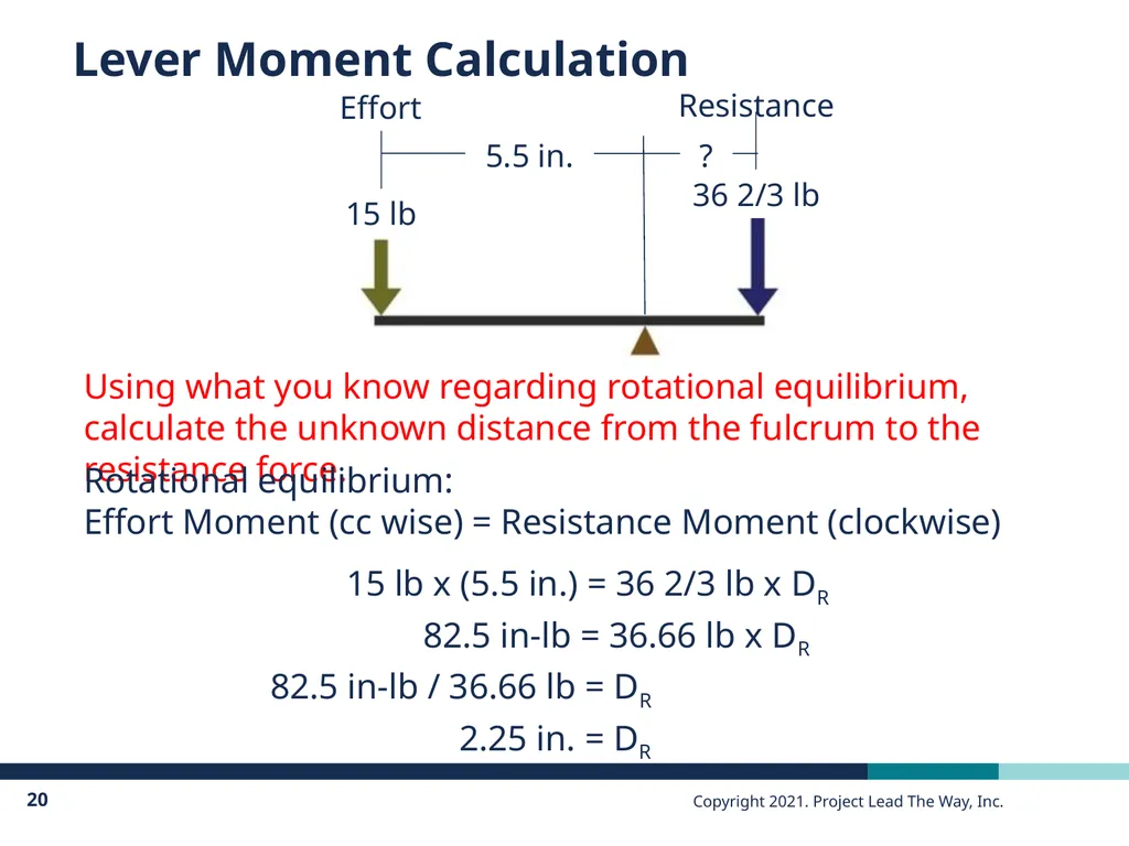
Lever Moment Calculation Resistance Using what you know regarding rotational equilibrium, calculate the unknown distance from the fulcrum to the resistance force. Rotational equilibrium:
Effort Moment (cc wise) = Resistance Moment (clockwise) 5.5 in. ? 15 lb 36 2/3 lb Effort<br>
21
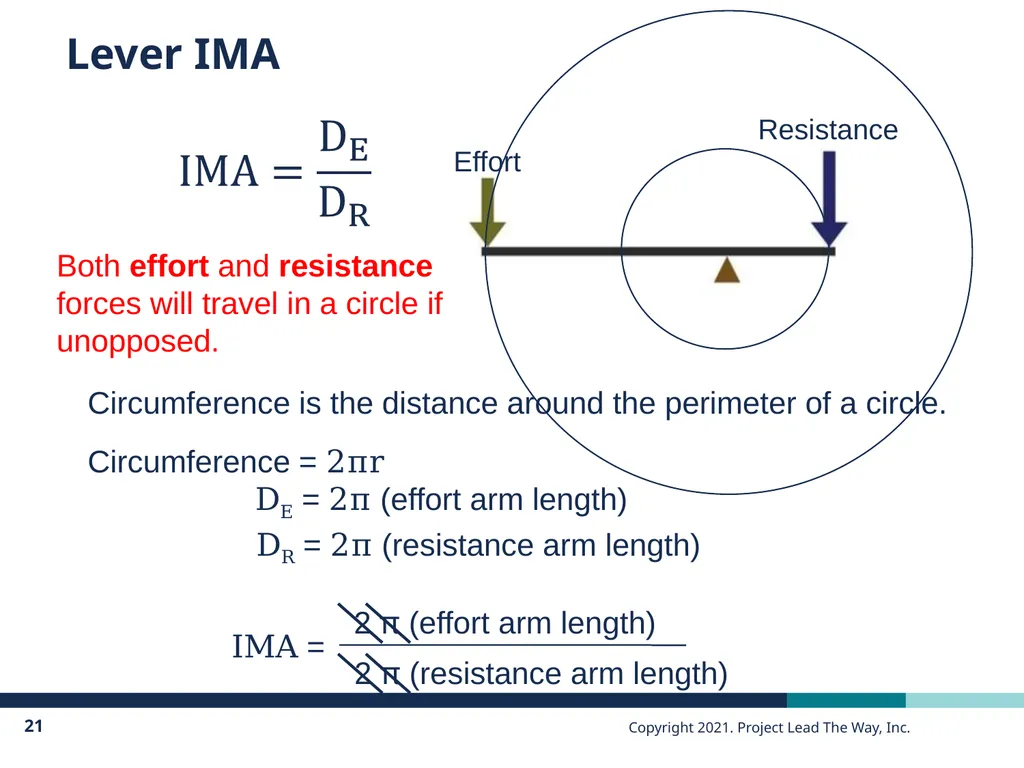
Lever IMA Resistance DE = 2π (effort arm length) Both effort and resistance forces will travel in a circle if unopposed. Circumference is the distance around the perimeter of a circle.
Circumference = 2πr DR = 2π (resistance arm length)<br>
22
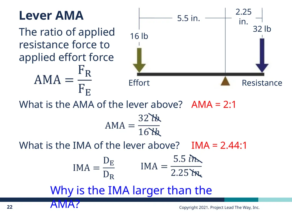
Lever AMA The ratio of applied resistance force to applied effort force What is the AMA of the lever above? AMA = 2:1 What is the IMA of the lever above? IMA = 2.44:1 Why is the IMA larger than the AMA?<br>
23
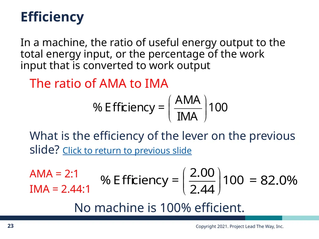
Efficiency In a machine, the ratio of useful energy output to the total energy input, or the percentage of the work input that is converted to work output The ratio of AMA to IMA What is the efficiency of the lever on the previous slide? Click to return to previous slide No machine is 100% efficient. AMA = 2:1 IMA = 2.44:1<br>
24
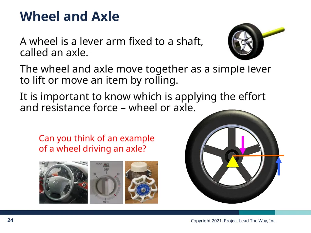
Wheel and Axle A wheel is a lever arm fixed to a shaft, �called an axle.
The wheel and axle move together as a simple lever to lift or move an item by rolling.
It is important to know which is applying the effort and resistance force – wheel or axle. Can you think of an example of a wheel driving an axle?<br>
25
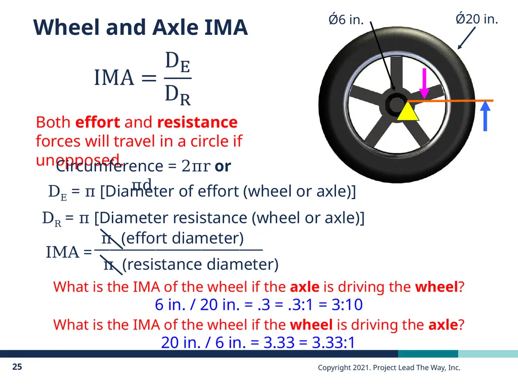
Wheel and Axle IMA DE = π [Diameter of effort (wheel or axle)] Both effort and resistance forces will travel in a circle if unopposed. Circumference = 2πr or πd DR = π [Diameter resistance (wheel or axle)] What is the IMA of the wheel if the axle is driving the wheel? What is the IMA of the wheel if the wheel is driving the axle? 6 in. / 20 in. = .3 = .3:1 = 3:10 20 in. / 6 in. = 3.33 = 3.33:1<br>
26
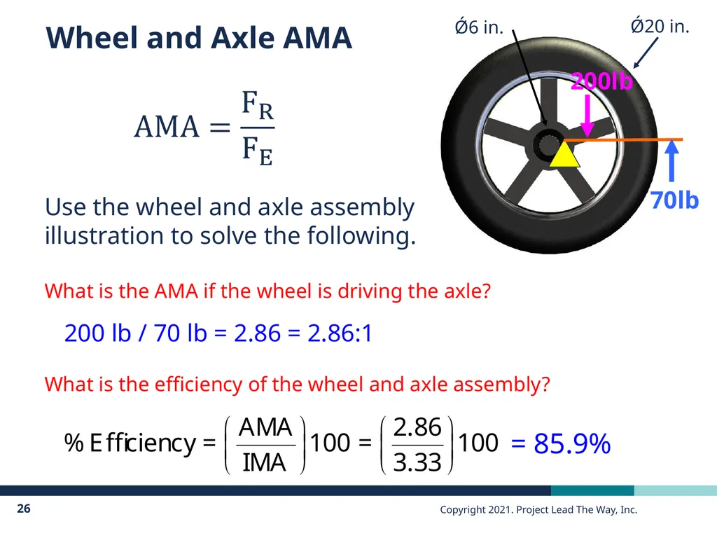
Wheel and Axle AMA 200lb 70lb What is the AMA if the wheel is driving the axle? Use the wheel and axle assembly illustration to solve the following. 200 lb / 70 lb = 2.86 = 2.86:1 What is the efficiency of the wheel and axle assembly? = 85.9%<br>
27
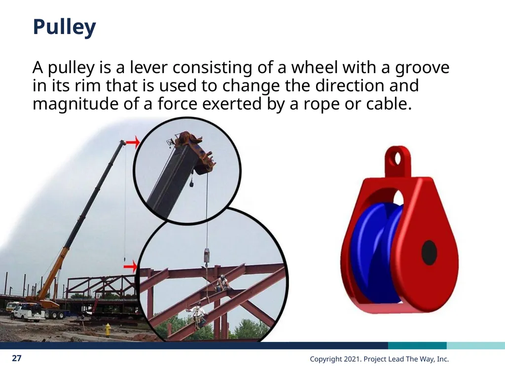
Pulley A pulley is a lever consisting of a wheel with a groove in its rim that is used to change the direction and magnitude of a force exerted by a rope or cable.<br>
28
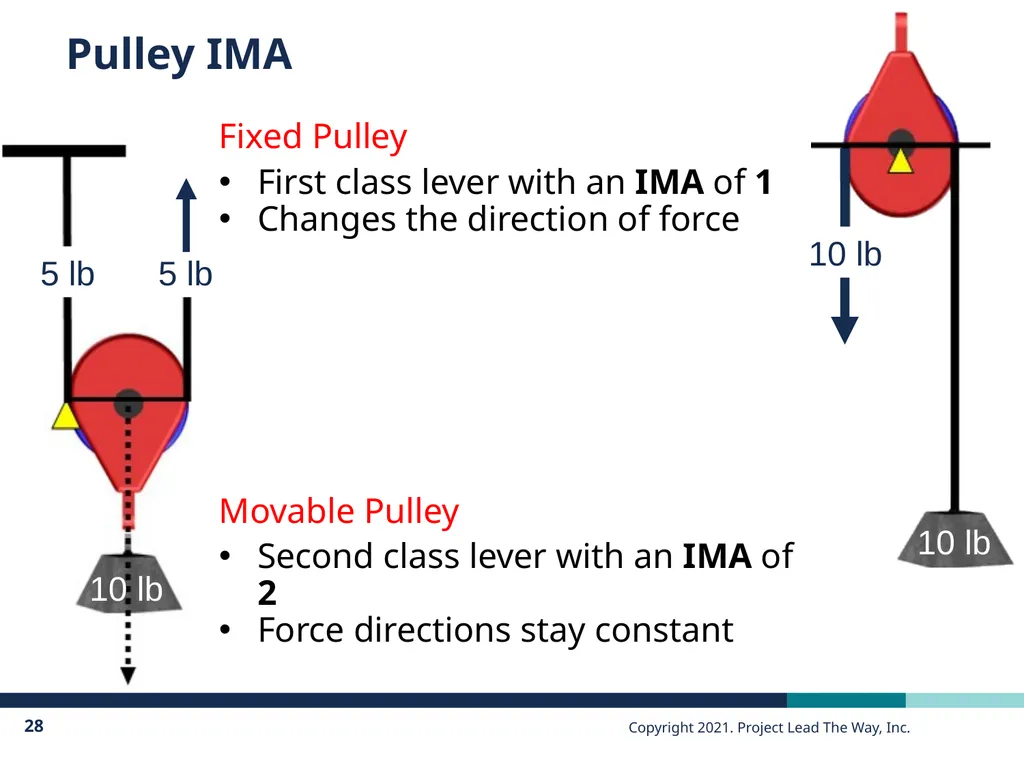
Pulley IMA Fixed Pulley
First class lever with an IMA of 1
Changes the direction of force
Movable Pulley
Second class lever with an IMA of 2
Force directions stay constant 10 lb 5 lb 5 lb 10 lb 10 lb<br>
29
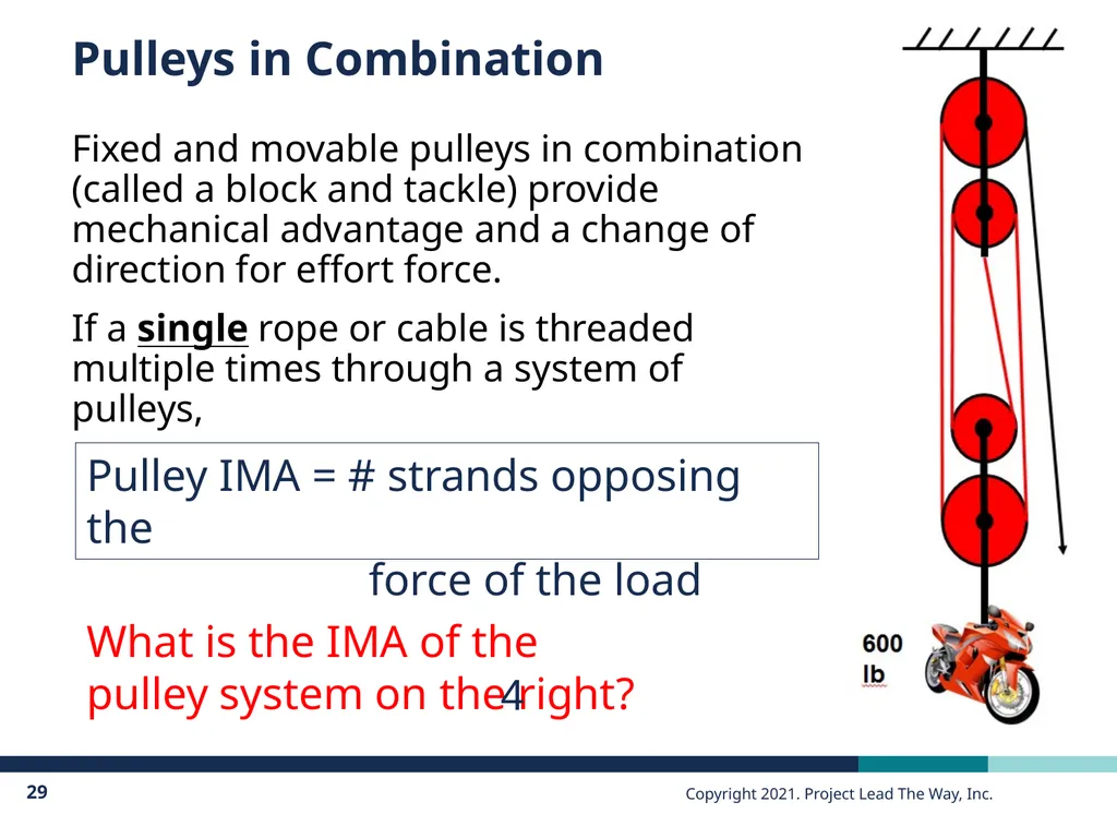
Pulleys in Combination Fixed and movable pulleys in combination (called a block and tackle) provide mechanical advantage and a change of direction for effort force.
If a single rope or cable is threaded multiple times through a system of pulleys, Pulley IMA = # strands opposing the
force of the load What is the IMA of the pulley system on the right? 4<br>
30
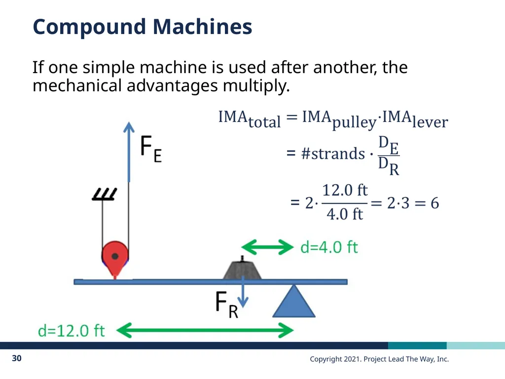
Compound Machines If one simple machine is used after another, the mechanical advantages multiply.<br>
31
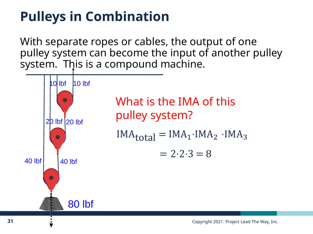
Pulleys in Combination With separate ropes or cables, the output of one pulley system can become the input of another pulley system. This is a compound machine. What is the IMA of this pulley system?<br>
32
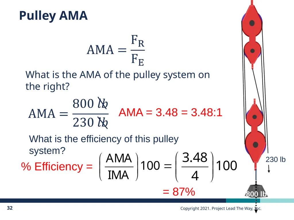
Pulley AMA What is the AMA of the pulley system on the right? AMA = 3.48 = 3.48:1 What is the efficiency of this pulley system? % Efficiency = = 87%<br>
33
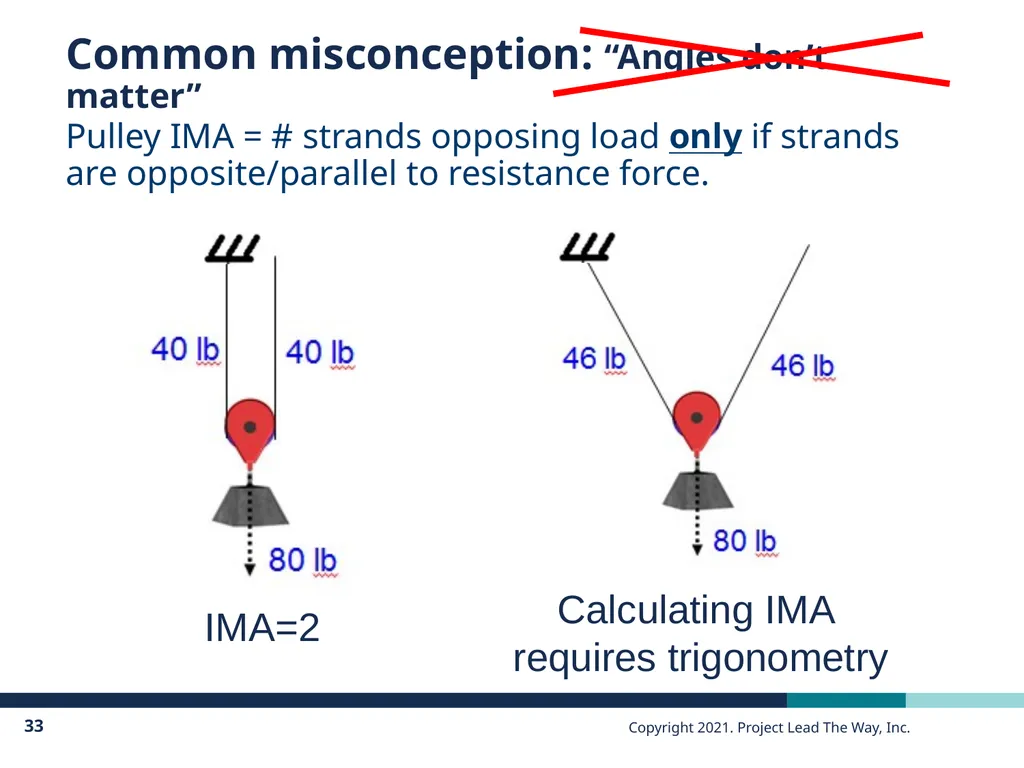
Common misconception: “Angles don’t matter” Pulley IMA = # strands opposing load only if strands are opposite/parallel to resistance force. IMA=2 Calculating IMA
requires trigonometry<br>
34
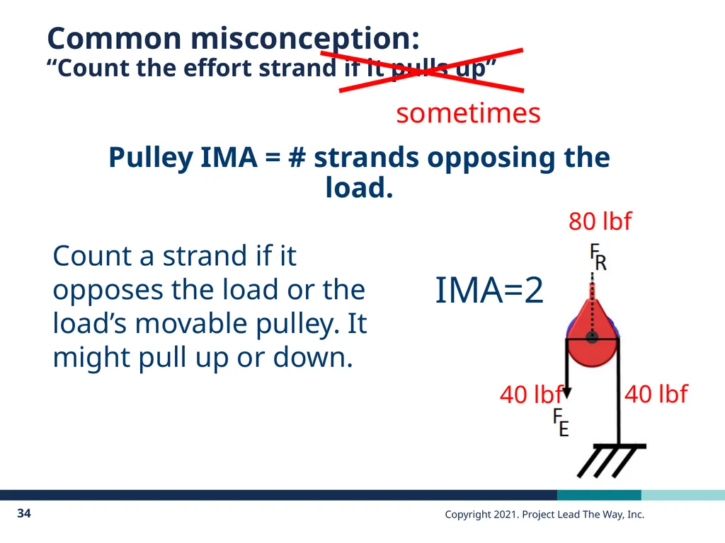
Common misconception:�“Count the effort strand if it pulls up” sometimes Pulley IMA = # strands opposing the load. IMA=2 Count a strand if it opposes the load or the load’s movable pulley. It might pull up or down. 80 lbf 40 lbf 40 lbf<br>
35
Image Resources Microsoft, Inc. (2008). Clip art. Retrieved January 10, 2008, from http://office.microsoft.com/en-us/clipart/default.aspx<br>