
PowerPoint 6: Structural science principles



Description: PowerPoint 6: Structural science principles PowerPoint presentation 2. Construction science principles 2.6 Structural science principles The effects of forces on buildings Gravity, weather elements, earthquakes and occupation all transmit
Related Topics
Download Presentation
"PowerPoint 6: Structural science principles" is the property of its rightful owner. Permission is granted to download and print the materials on this website for personal, non-commercial use only, and to display it on your personal computer provided you do not modify the materials and that you retain all copyright notices contained in the materials. By downloading content from our website, you accept the terms of this agreement.
Presentation Transcript
slide1. PowerPoint 6: Structural science principles PowerPoint presentation 2. Construction science principles
2.6 Structural science principles<br>
slide2. The effects of forces on buildings Gravity, weather elements, earthquakes and occupation all transmit forces onto a building’s primary superstructure.
It is critical that calculations during building design ensure buildings and materials used can withstand the forces acting upon them.
Loads can be live or dead. Dead loads are static, and might include walls, ceilings and floors. Live loads are variable or moving and come from the occupation of the building (eg furniture, equipment, people).
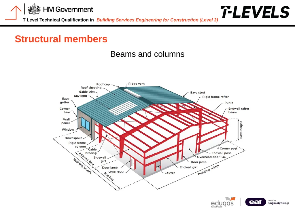
Beams and columns are the main parts of a structural frame. Beams transfer the total load to the columns, and columns carry it to the foundations, providing stability to the structure.<br>
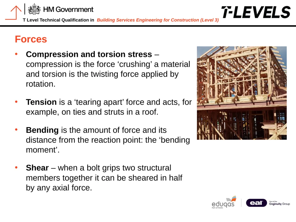
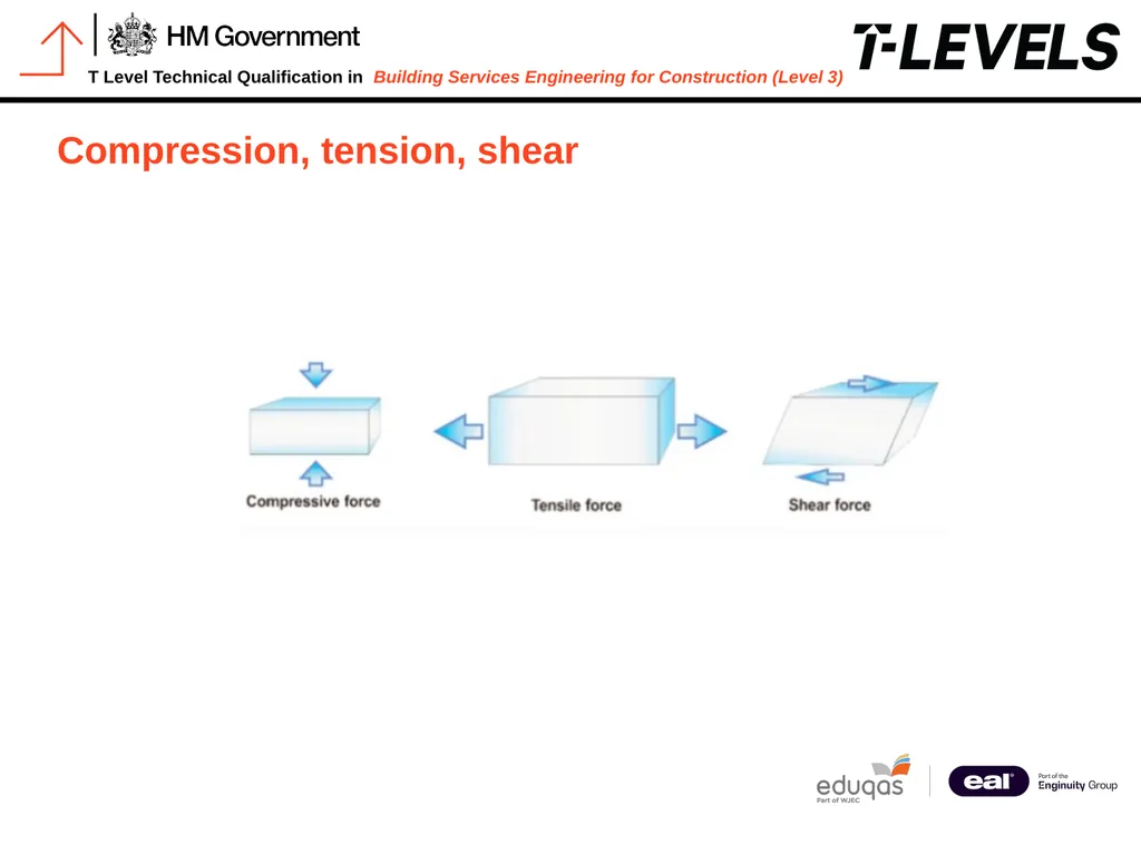
slide3. Forces Compression and torsion stress – compression is the force ‘crushing’ a material and torsion is the twisting force applied by rotation.
Tension is a ‘tearing apart’ force and acts, for example, on ties and struts in a roof.
Bending is the amount of force and its distance from the reaction point: the ‘bending moment’.
Shear – when a bolt grips two structural members together it can be sheared in half by any axial force.<br>
slide4. Compression, tension, shear<br>
slide5. Loads and material properties Three types of load will act upon structures.
Vertical – a vertical load is a ‘straight-down’ force acting under gravity.
Horizontal – forces such as the wind pressing on the side of a building or structure.
Longitudinal – forces along a length, such as tension in a railway rail due to heat expansion in the summer.<br>
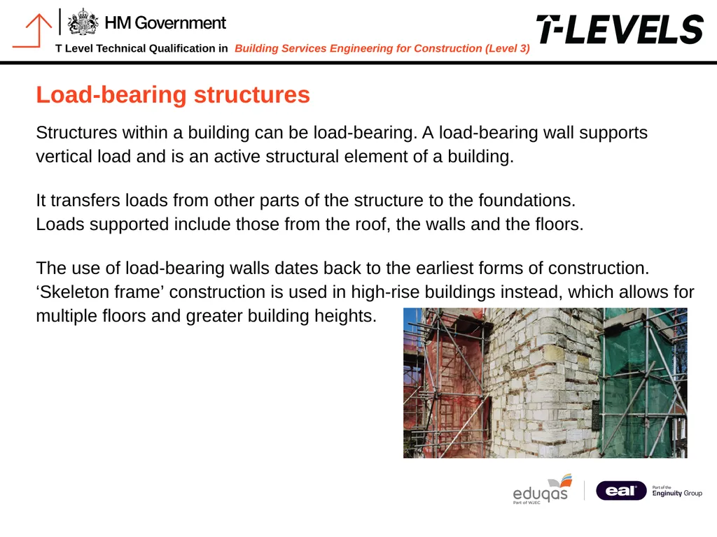
slide6. Load-bearing structures Structures within a building can be load-bearing. A load-bearing wall supports vertical load and is an active structural element of a building.
It transfers loads from other parts of the structure to the foundations. Loads supported include those from the roof, the walls and the floors.
The use of load-bearing walls dates back to the earliest forms of construction. ‘Skeleton frame’ construction is used in high-rise buildings instead, which allows for multiple floors and greater building heights.<br>
slide7. Material properties for load-bearing Strength – the ability of a material to withstand forces exerted upon it (comparisons can be made across a range).
Malleability – the ability of a material to be changed in shape without failing (eg buckling).
Hardness – the ability of a material to resist impact and remain undeformed.
Elasticity – the ability of a material to stretch and then return back to its original shape. Wrought iron (that has been heated and worked into shape) has a much higher tensile strength than cast iron (molten metal poured into a mould). Because it resists fatigue, it was used for horizontal beams in construction (eg bridges). Steel is now more commonly used instead.<br>
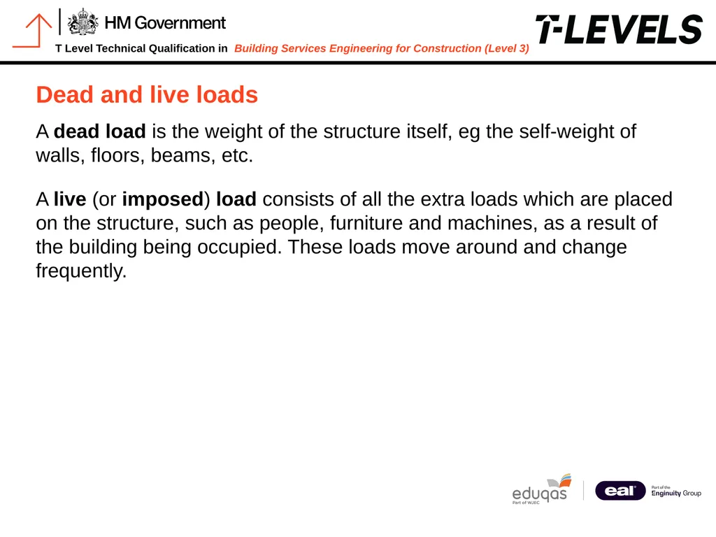
slide8. Dead and live loads A dead load is the weight of the structure itself, eg the self-weight of walls, floors, beams, etc.
A live (or imposed) load consists of all the extra loads which are placed on the structure, such as people, furniture and machines, as a result of the building being occupied. These loads move around and change frequently.<br>
slide9. Structural members Footings, also known as foundations
Walls<br>
slide10. Structural members Beams and columns<br>
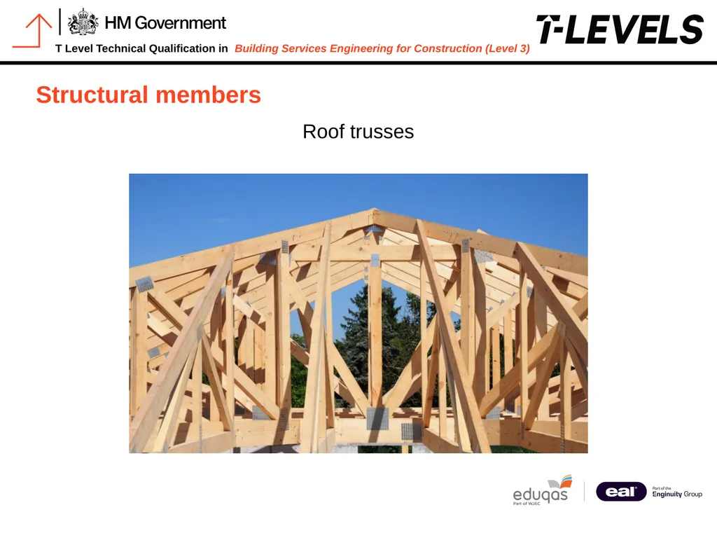
slide11. Structural members Roof trusses<br>
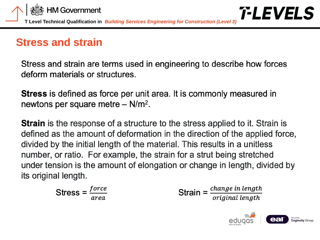
slide12. Stress and strain<br>
slide13. Calculations for holes and notches When installing pipework or cabling, floor or ceiling joists may need to be notched or drilled. But this could weaken joists to such an extent that they become structurally unsound.
It is crucial to understand and calculate permitted notching zones and maximum depths of holes and notches.
The location and depth of the hole or notch will depend upon the span of the timber joist and the depth of the timber.
For example, timber of a depth of 200mm can have a hole no larger than 50mm diameter and 25mm depth. Such calculations are subject to quite complex guidance.<br>
slide14. Holes and notches The link below provides a guide to safe hole and notch locations and relative hole sizes.
https://www.labc.co.uk/news/how-get-it-right-notches-holes-solid-timber-joists<br>
slide15. Approved document A: Structure Important calculations conducted in structural design are those for beam, load and column.
Calculations are required by building control in order to comply with Approved document A: Structure which is an approved document from the building regulations.
Calculations must prove that sufficient safety factors have been engineered into a structure so that it is safe for occupation.
Part A covers structural work in steel, concrete, timber, masonry and aluminum, dimensions and thicknesses required, and requirements for foundations, wall cladding and roof covering.<br>
slide16. Documentation Approved document A can be found here:
BR_PDF_AD_A_2013.pdf (publishing.service.gov.uk)
You should thoroughly familiarise yourself with this document.<br>
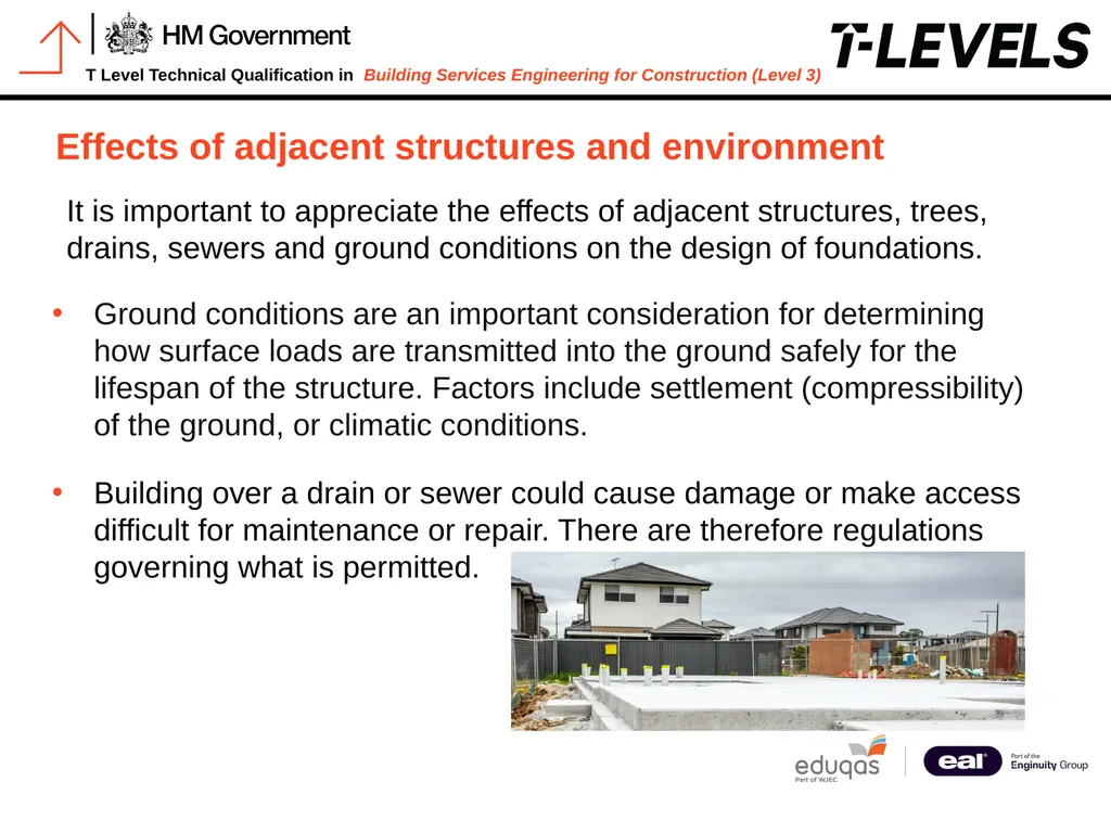
slide17. Effects of adjacent structures and environment Ground conditions are an important consideration for determining how surface loads are transmitted into the ground safely for the lifespan of the structure. Factors include settlement (compressibility) of the ground, or climatic conditions.
Building over a drain or sewer could cause damage or make access difficult for maintenance or repair. There are therefore regulations governing what is permitted. It is important to appreciate the effects of adjacent structures, trees, drains, sewers and ground conditions on the design of foundations.<br>
slide18. Foundations and trees The link below provides a guide to building near trees and the precautions required in relation to foundations. The growth of nearby trees and roots can cause damage to foundations. This can be avoided by locating structures and services at a safe distance.
NHBC Standards Chapter 4.2 – Building near trees | New Build Inspections<br>
slide19. Any questions?
Copyright in this document belongs to and is used under licence from the Department for Education, © 2025.
‘T-LEVELS’ and ‘T Level’ are registered trademarks of the Department for Education.
WJEC is authorised by the Department for Education to develop and deliver this T Level Technical Qualification.
WJEC operates in England under the name Eduqas which is a registered trademark of WJEC.<br>
2.6 Structural science principles<br>
slide2. The effects of forces on buildings Gravity, weather elements, earthquakes and occupation all transmit forces onto a building’s primary superstructure.
It is critical that calculations during building design ensure buildings and materials used can withstand the forces acting upon them.
Loads can be live or dead. Dead loads are static, and might include walls, ceilings and floors. Live loads are variable or moving and come from the occupation of the building (eg furniture, equipment, people).
Beams and columns are the main parts of a structural frame. Beams transfer the total load to the columns, and columns carry it to the foundations, providing stability to the structure.<br>
slide3. Forces Compression and torsion stress – compression is the force ‘crushing’ a material and torsion is the twisting force applied by rotation.
Tension is a ‘tearing apart’ force and acts, for example, on ties and struts in a roof.
Bending is the amount of force and its distance from the reaction point: the ‘bending moment’.
Shear – when a bolt grips two structural members together it can be sheared in half by any axial force.<br>
slide4. Compression, tension, shear<br>
slide5. Loads and material properties Three types of load will act upon structures.
Vertical – a vertical load is a ‘straight-down’ force acting under gravity.
Horizontal – forces such as the wind pressing on the side of a building or structure.
Longitudinal – forces along a length, such as tension in a railway rail due to heat expansion in the summer.<br>
slide6. Load-bearing structures Structures within a building can be load-bearing. A load-bearing wall supports vertical load and is an active structural element of a building.
It transfers loads from other parts of the structure to the foundations. Loads supported include those from the roof, the walls and the floors.
The use of load-bearing walls dates back to the earliest forms of construction. ‘Skeleton frame’ construction is used in high-rise buildings instead, which allows for multiple floors and greater building heights.<br>
slide7. Material properties for load-bearing Strength – the ability of a material to withstand forces exerted upon it (comparisons can be made across a range).
Malleability – the ability of a material to be changed in shape without failing (eg buckling).
Hardness – the ability of a material to resist impact and remain undeformed.
Elasticity – the ability of a material to stretch and then return back to its original shape. Wrought iron (that has been heated and worked into shape) has a much higher tensile strength than cast iron (molten metal poured into a mould). Because it resists fatigue, it was used for horizontal beams in construction (eg bridges). Steel is now more commonly used instead.<br>
slide8. Dead and live loads A dead load is the weight of the structure itself, eg the self-weight of walls, floors, beams, etc.
A live (or imposed) load consists of all the extra loads which are placed on the structure, such as people, furniture and machines, as a result of the building being occupied. These loads move around and change frequently.<br>
slide9. Structural members Footings, also known as foundations
Walls<br>
slide10. Structural members Beams and columns<br>
slide11. Structural members Roof trusses<br>
slide12. Stress and strain<br>
slide13. Calculations for holes and notches When installing pipework or cabling, floor or ceiling joists may need to be notched or drilled. But this could weaken joists to such an extent that they become structurally unsound.
It is crucial to understand and calculate permitted notching zones and maximum depths of holes and notches.
The location and depth of the hole or notch will depend upon the span of the timber joist and the depth of the timber.
For example, timber of a depth of 200mm can have a hole no larger than 50mm diameter and 25mm depth. Such calculations are subject to quite complex guidance.<br>
slide14. Holes and notches The link below provides a guide to safe hole and notch locations and relative hole sizes.
https://www.labc.co.uk/news/how-get-it-right-notches-holes-solid-timber-joists<br>
slide15. Approved document A: Structure Important calculations conducted in structural design are those for beam, load and column.
Calculations are required by building control in order to comply with Approved document A: Structure which is an approved document from the building regulations.
Calculations must prove that sufficient safety factors have been engineered into a structure so that it is safe for occupation.
Part A covers structural work in steel, concrete, timber, masonry and aluminum, dimensions and thicknesses required, and requirements for foundations, wall cladding and roof covering.<br>
slide16. Documentation Approved document A can be found here:
BR_PDF_AD_A_2013.pdf (publishing.service.gov.uk)
You should thoroughly familiarise yourself with this document.<br>
slide17. Effects of adjacent structures and environment Ground conditions are an important consideration for determining how surface loads are transmitted into the ground safely for the lifespan of the structure. Factors include settlement (compressibility) of the ground, or climatic conditions.
Building over a drain or sewer could cause damage or make access difficult for maintenance or repair. There are therefore regulations governing what is permitted. It is important to appreciate the effects of adjacent structures, trees, drains, sewers and ground conditions on the design of foundations.<br>
slide18. Foundations and trees The link below provides a guide to building near trees and the precautions required in relation to foundations. The growth of nearby trees and roots can cause damage to foundations. This can be avoided by locating structures and services at a safe distance.
NHBC Standards Chapter 4.2 – Building near trees | New Build Inspections<br>
slide19. Any questions?
Copyright in this document belongs to and is used under licence from the Department for Education, © 2025.
‘T-LEVELS’ and ‘T Level’ are registered trademarks of the Department for Education.
WJEC is authorised by the Department for Education to develop and deliver this T Level Technical Qualification.
WJEC operates in England under the name Eduqas which is a registered trademark of WJEC.<br>