04
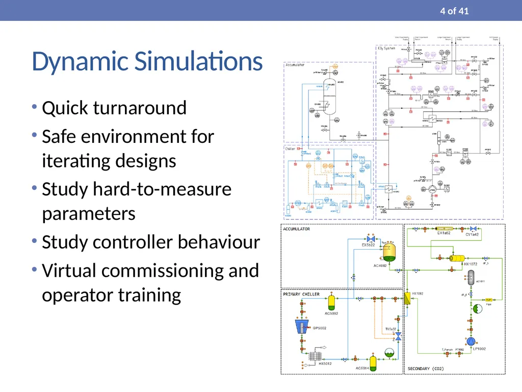
Dynamic Simulations Quick turnaround
Safe environment for iterating designs
Study hard-to-measure parameters
Study controller behaviour
Virtual commissioning and operator training 4 of 41<br>
05
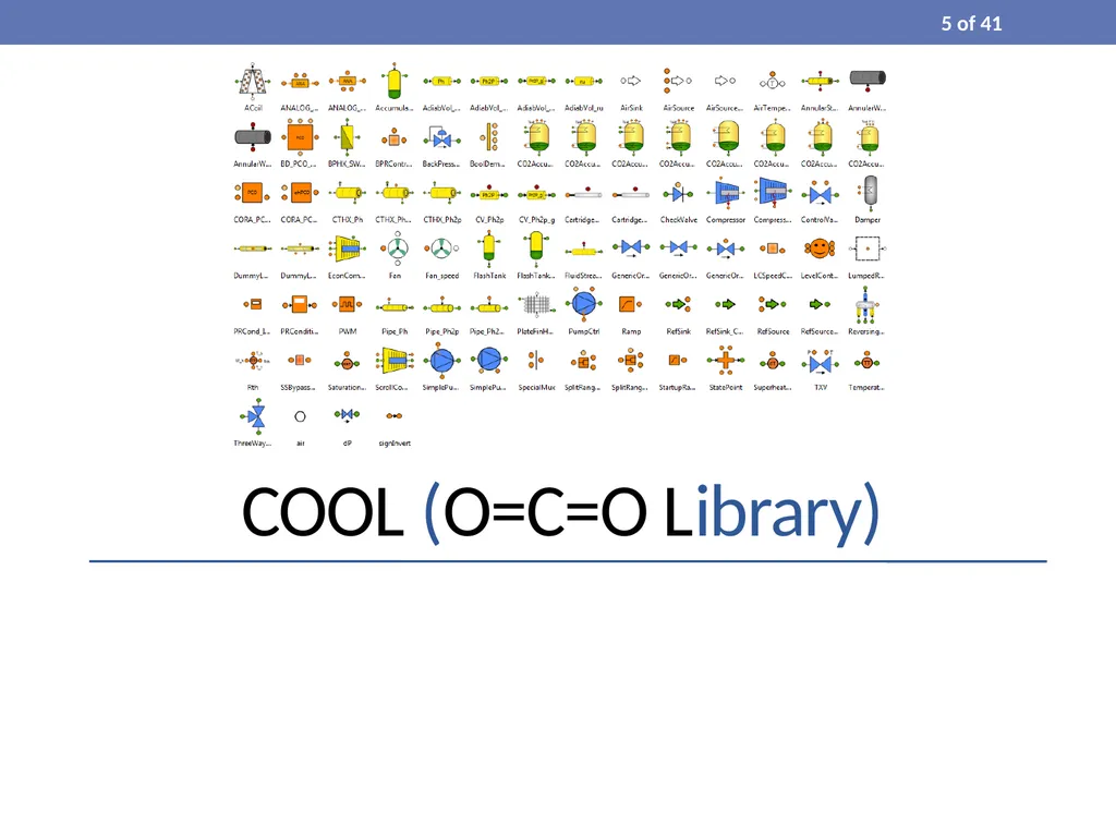
COOL (O=C=O Library) 5 of 41<br>
06
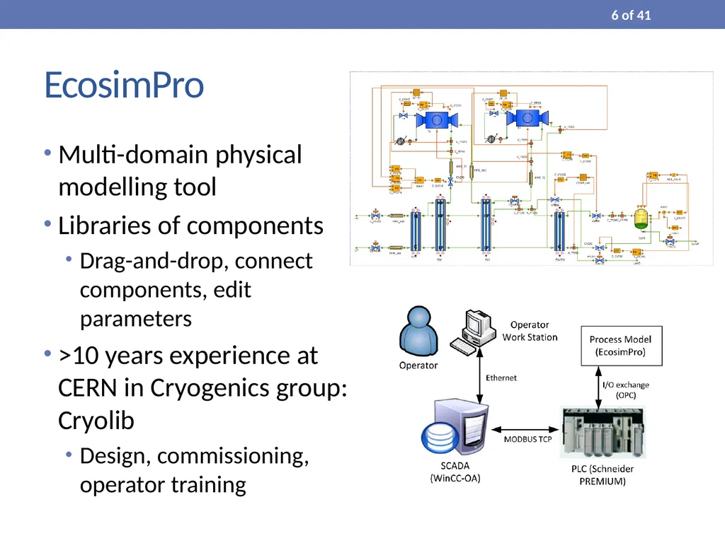
EcosimPro Multi-domain physical modelling tool
Libraries of components
Drag-and-drop, connect components, edit parameters
>10 years experience at CERN in Cryogenics group: Cryolib
Design, commissioning, operator training 6 of 41<br>
07
CO2L: Building upon Cryolib CO2-specific components
Pumps, heat exchangers, accumulators, chiller components etc.
CO2-specific controller objects
PCOs, stepper logic, interlocks etc.
CO2-specific constitutive equations (heat transfer coefficient)
Two-phase flow modelling 7 of 41<br>
08
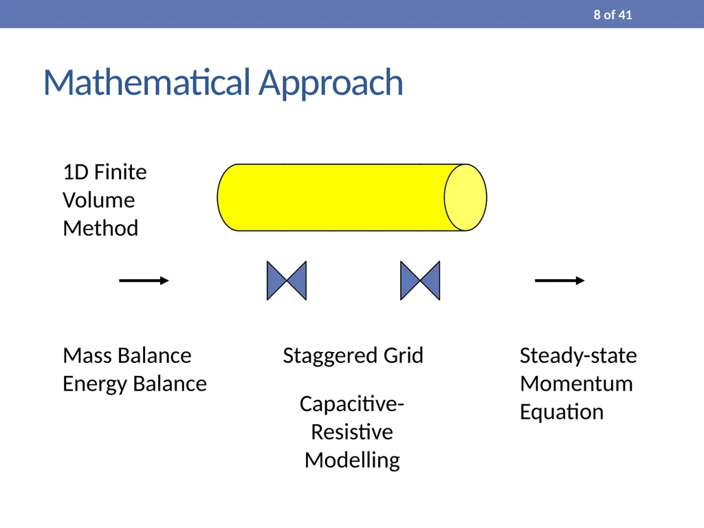
Mathematical Approach Mass Balance
Energy Balance Staggered Grid Capacitive-Resistive Modelling Steady-state Momentum Equation 1D Finite Volume Method 8 of 41<br>
09
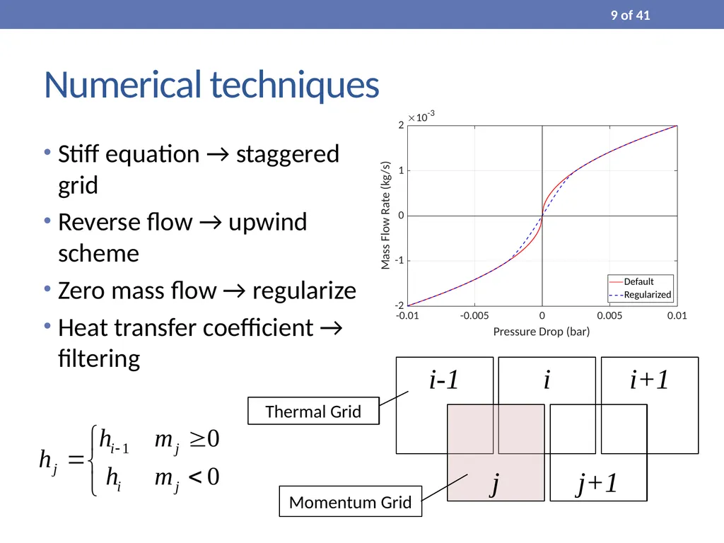
Numerical techniques Stiff equation → staggered grid
Reverse flow → upwind scheme
Zero mass flow → regularize
Heat transfer coefficient → filtering i i-1 i+1 j j+1 9 of 41 Thermal Grid Momentum Grid<br>
10
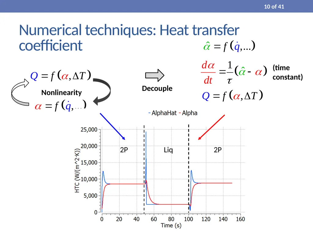
Numerical techniques: Heat transfer coefficient Decouple Nonlinearity (time constant) 10 of 41<br>
11
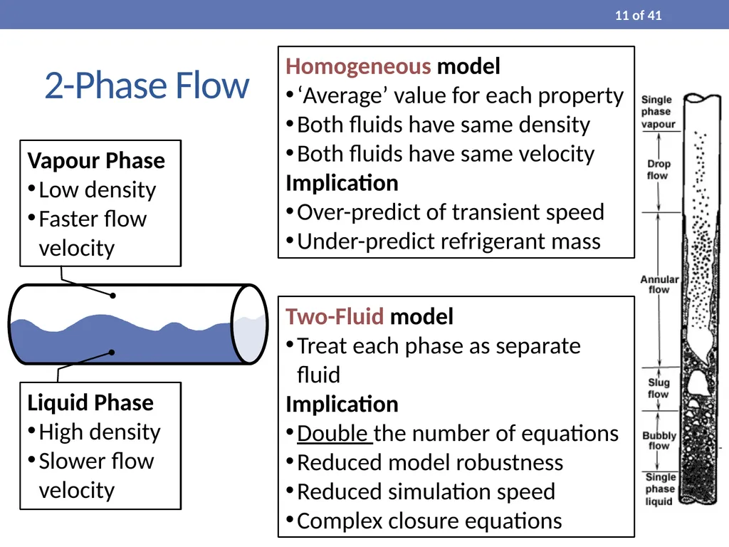
2-Phase Flow Homogeneous model
‘Average’ value for each property
Both fluids have same density
Both fluids have same velocity
Implication
Over-predict of transient speed
Under-predict refrigerant mass Two-Fluid model
Treat each phase as separate fluid
Implication
Double the number of equations
Reduced model robustness
Reduced simulation speed
Complex closure equations 11 of 41<br>
12
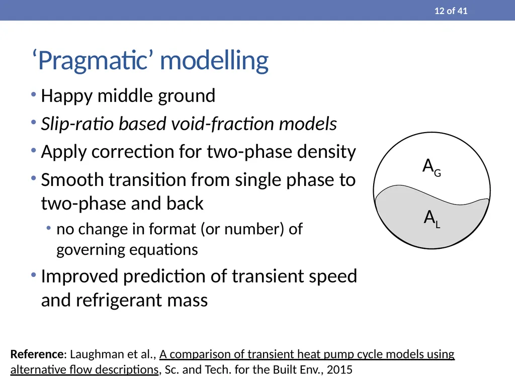
‘Pragmatic’ modelling Happy middle ground
Slip-ratio based void-fraction models
Apply correction for two-phase density
Smooth transition from single phase to two-phase and back
no change in format (or number) of governing equations
Improved prediction of transient speed and refrigerant mass Reference: Laughman et al., A comparison of transient heat pump cycle models using
alternative flow descriptions, Sc. and Tech. for the Built Env., 2015 12 of 41<br>
13
Validating a Residential Heat Pump 13 of 41<br>
14
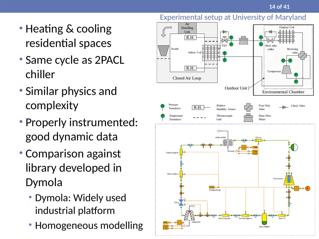
Heating & cooling residential spaces
Same cycle as 2PACL chiller
Similar physics and complexity
Properly instrumented: good dynamic data
Comparison against library developed in Dymola
Dymola: Widely used industrial platform
Homogeneous modelling Experimental setup at University of Maryland 14 of 41<br>
15
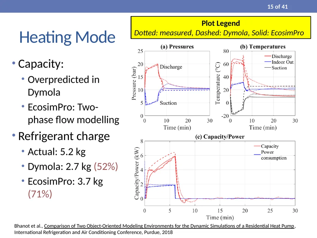
Heating Mode Capacity:
Overpredicted in Dymola
EcosimPro: Two-phase flow modelling
Refrigerant charge
Actual: 5.2 kg
Dymola: 2.7 kg (52%)
EcosimPro: 3.7 kg (71%) Plot Legend
Dotted: measured, Dashed: Dymola, Solid: EcosimPro Bhanot et al., Comparison of Two Object-Oriented Modeling Environments for the Dynamic Simulations of a Residential Heat Pump, International Refrigeration and Air Conditioning Conference, Purdue, 2018 15 of 41<br>
16
2PACL Modelling 16 of 41<br>
17
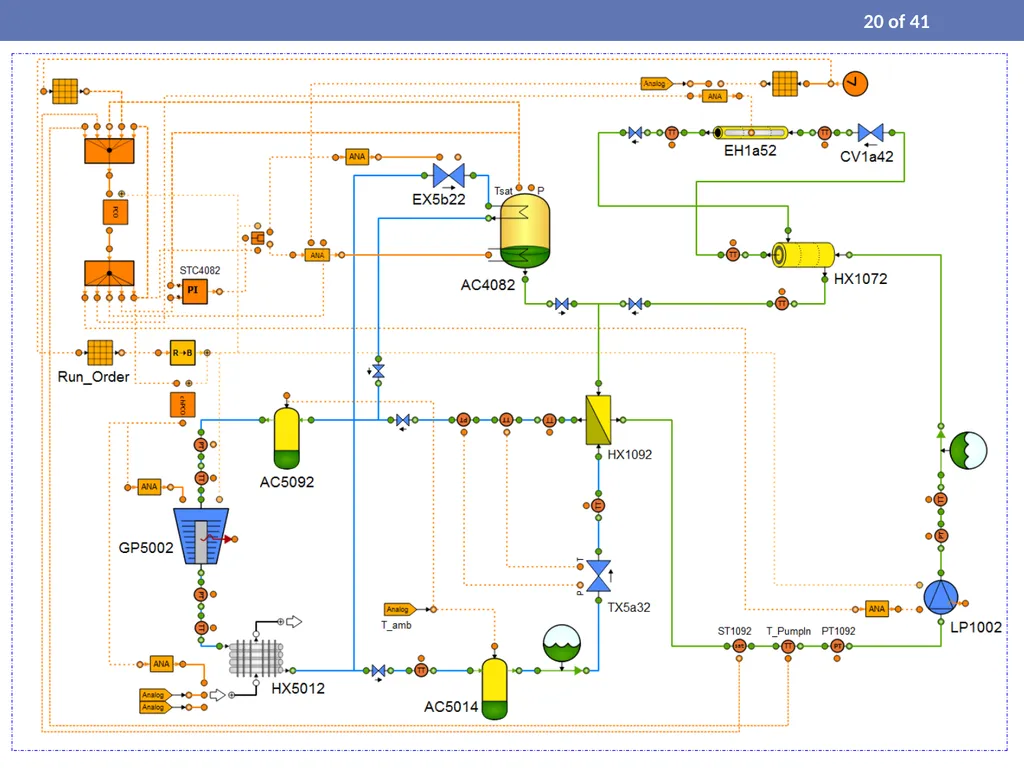
Simulating CORA 17 of 41<br>
18
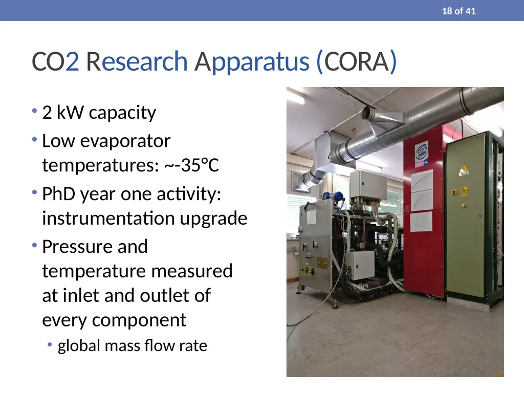
CO2 Research Apparatus (CORA) 2 kW capacity
Low evaporator temperatures: ~-35°C
PhD year one activity: instrumentation upgrade
Pressure and temperature measured at inlet and outlet of every component
global mass flow rate 18 of 41<br>
19
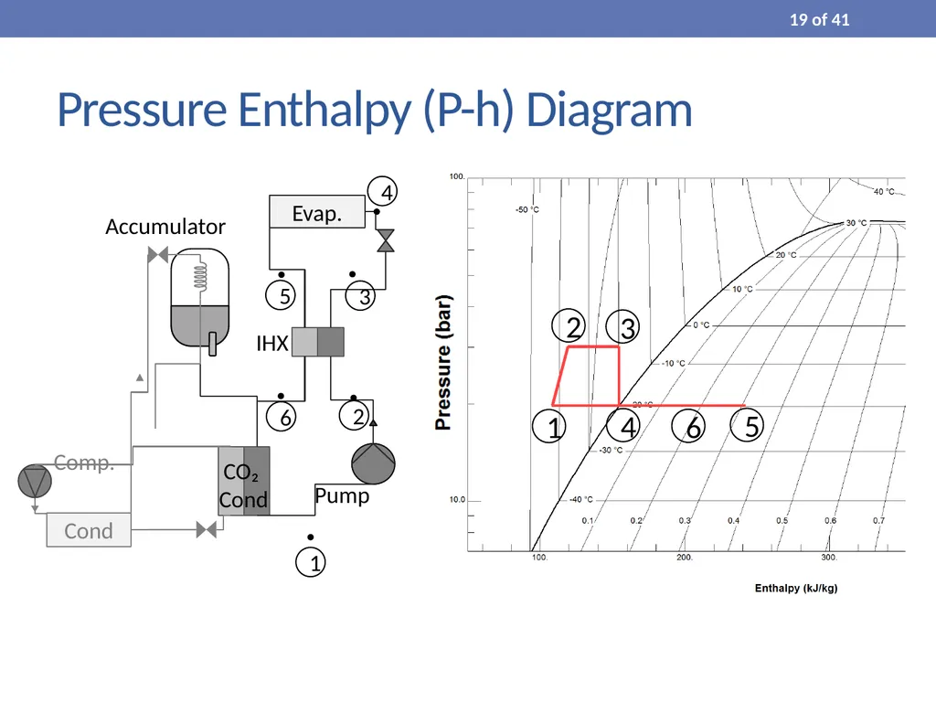
1 2 3 4 5 6 Pressure Enthalpy (P-h) Diagram 19 of 41<br>
21
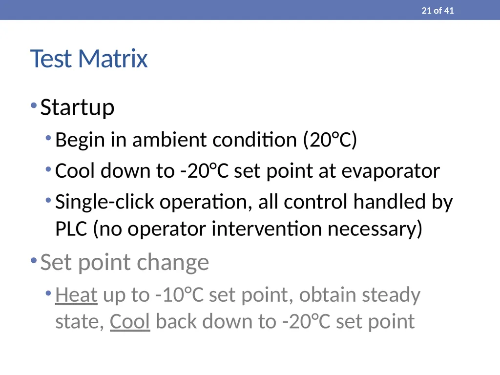
Test Matrix Startup
Begin in ambient condition (20°C)
Cool down to -20°C set point at evaporator
Single-click operation, all control handled by PLC (no operator intervention necessary)
Set point change
Heat up to -10°C set point, obtain steady state, Cool back down to -20°C set point 21 of 41<br>
22
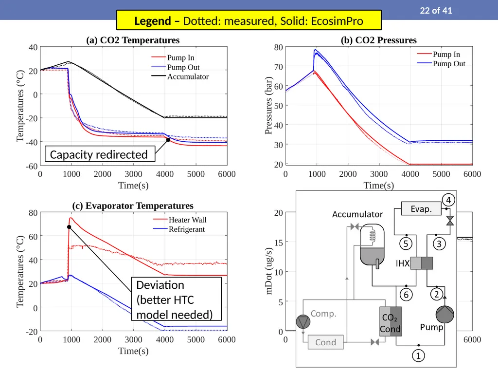
Deviation (better HTC model needed) Capacity redirected Legend – Dotted: measured, Solid: EcosimPro 22 of 41<br>
23
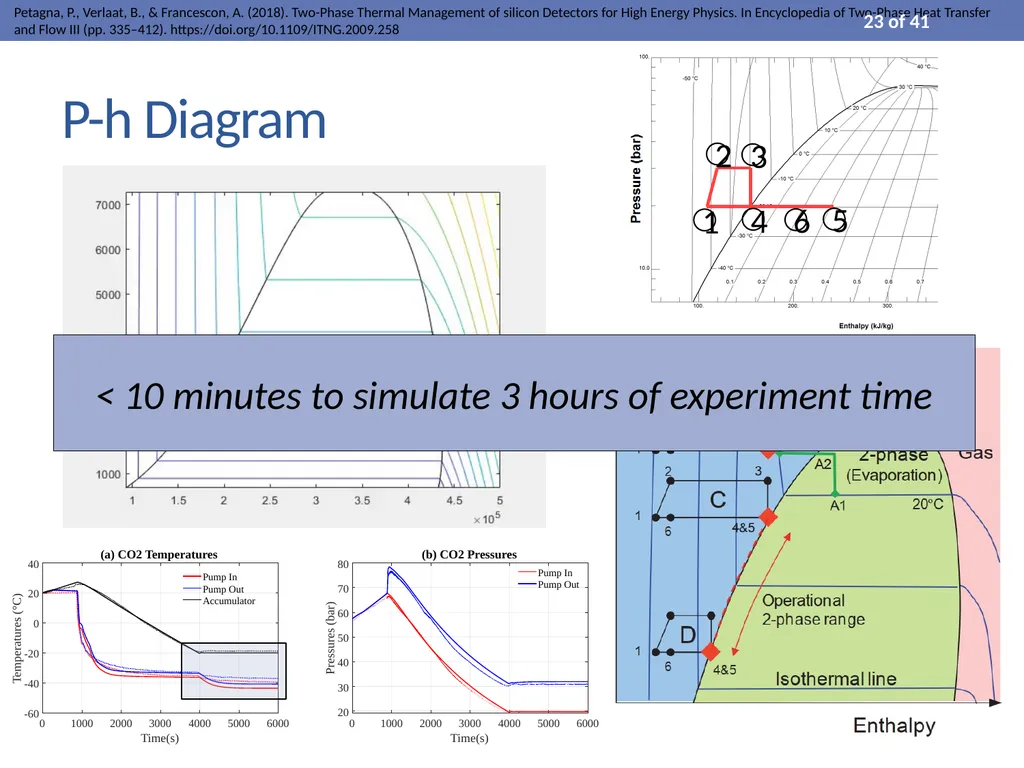
P-h Diagram < 10 minutes to simulate 3 hours of experiment time Petagna, P., Verlaat, B., & Francescon, A. (2018). Two-Phase Thermal Management of silicon Detectors for High Energy Physics. In Encyclopedia of Two-Phase Heat Transfer and Flow III (pp. 335–412). https://doi.org/10.1109/ITNG.2009.258 23 of 41<br>
24
Accumulator Sizing 24 of 41 [End of Validation Phase]
New System Design: DEMO<br>
25
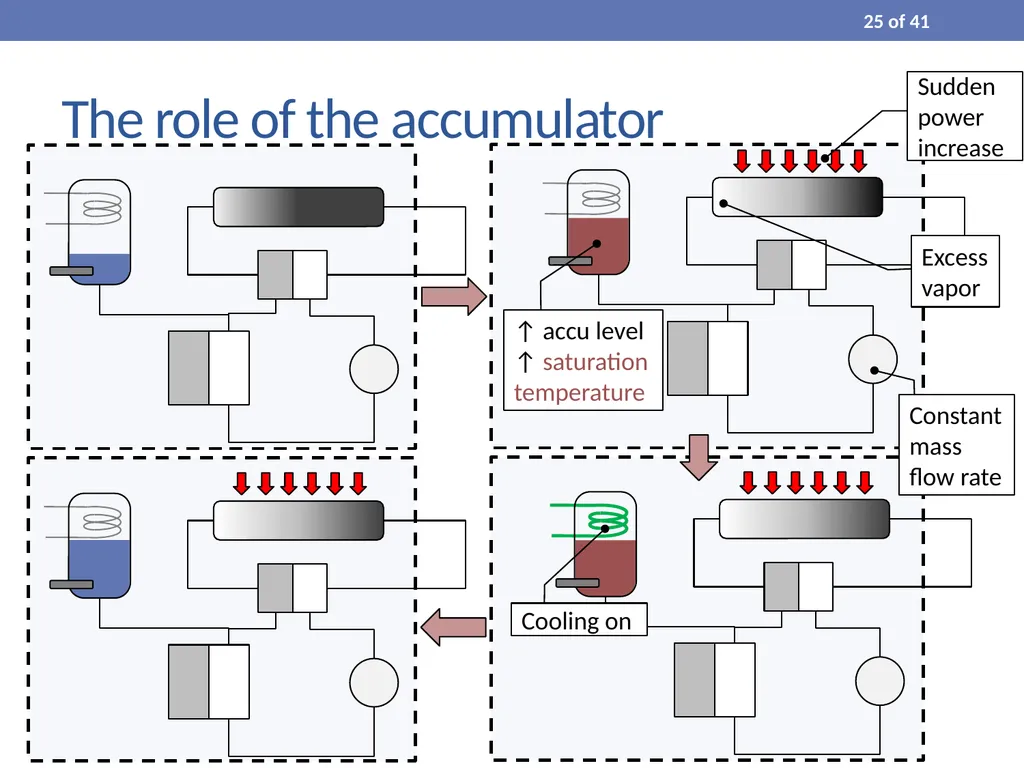
The role of the accumulator Sudden power increase Excess vapor ↑ accu level
↑ saturation temperature Cooling on Constant mass flow rate 25 of 41<br>
26
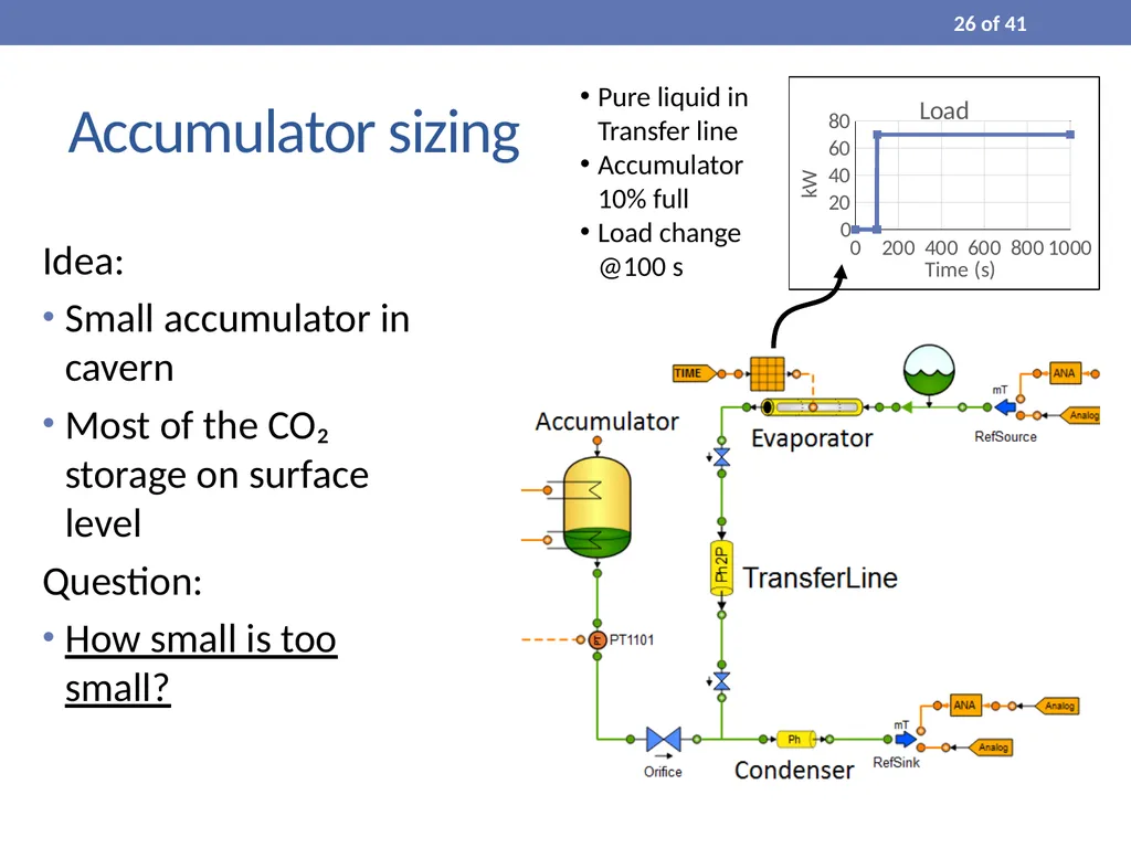
Accumulator sizing Idea:
Small accumulator in cavern
Most of the CO₂ storage on surface level
Question:
How small is too small? Pure liquid in Transfer line
Accumulator 10% full
Load change @100 s 26 of 41<br>
27
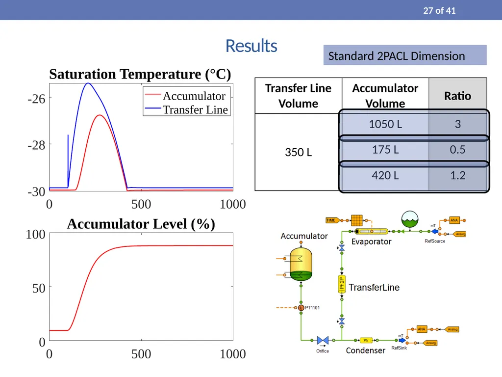
Results Standard 2PACL Dimension 27 of 41<br>
28
Simulating Surface-Storage 28 of 41<br>
29
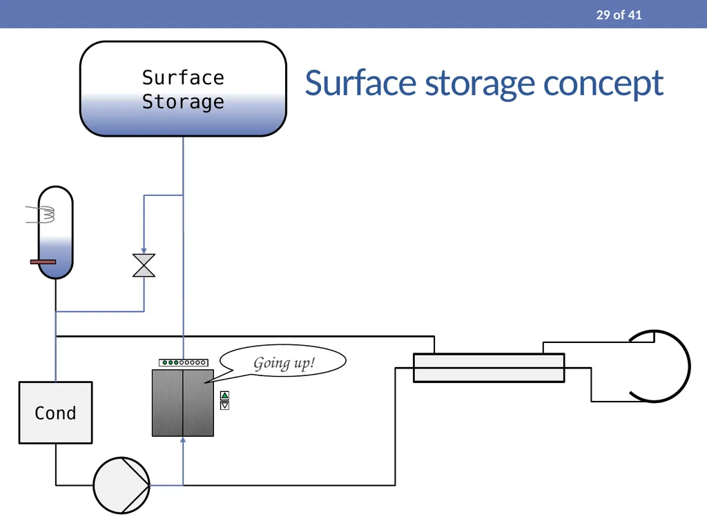
Surface storage concept Cond Going up! 29 of 41<br>
30
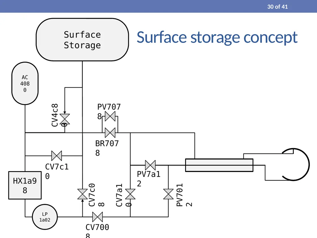
Surface storage concept 30 of 41<br>
31
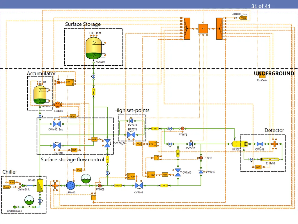
New Baby-Demo concept (spring 2019) 31 of 41<br>
32
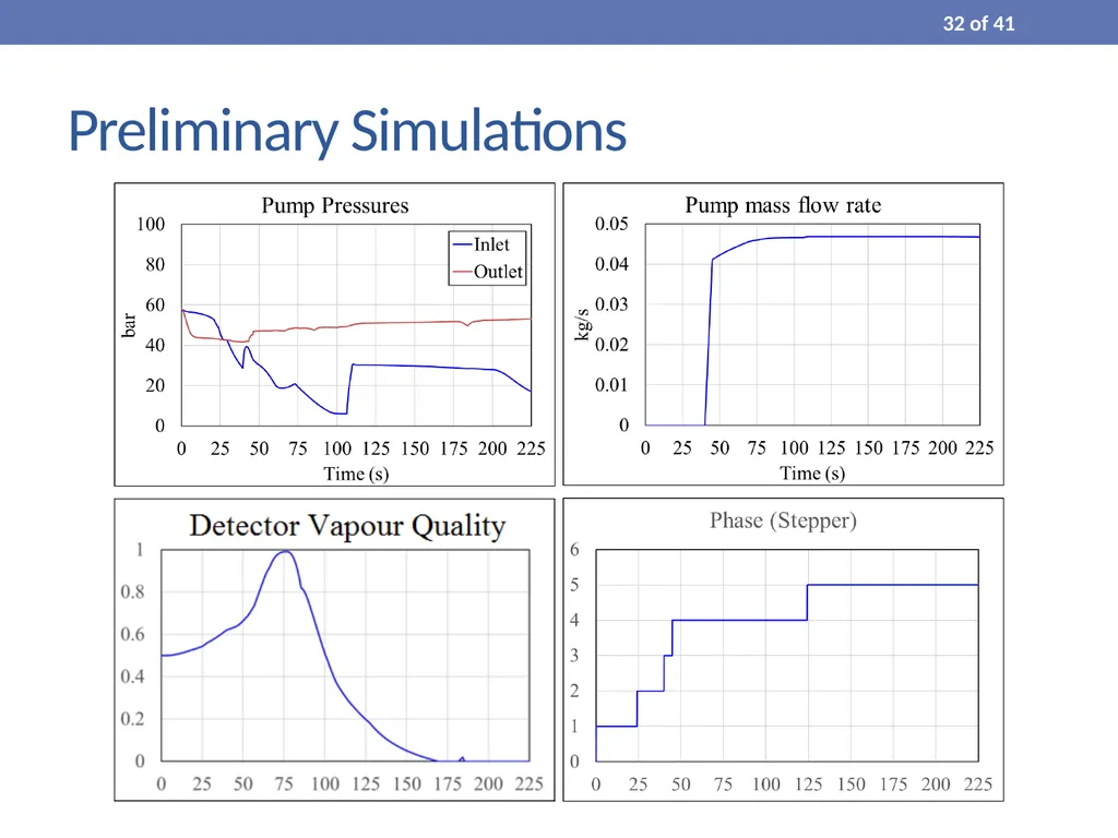
Preliminary Simulations 32 of 41<br>
33
Virtual Commissioning Process simulation controlled by real PLC 33 of 41<br>
34
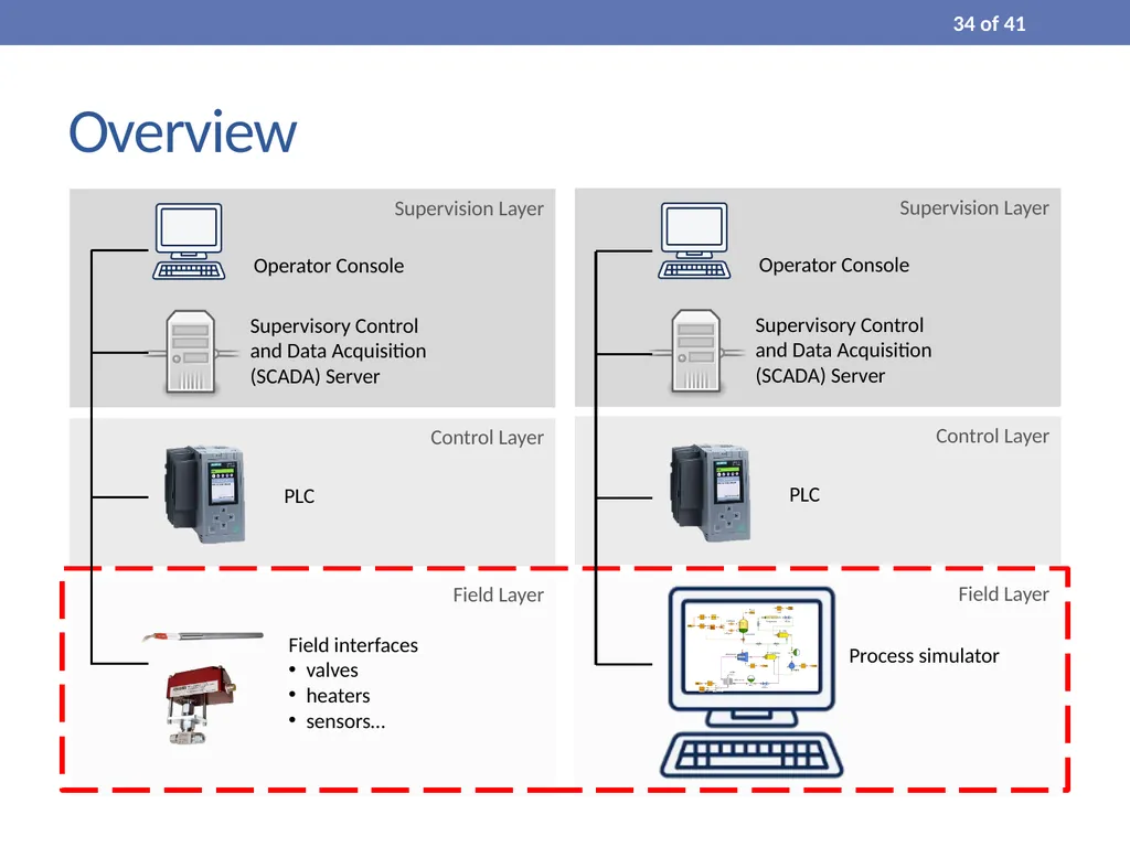
Field Layer Control Layer Supervision Layer Operator Console Supervisory Control and Data Acquisition (SCADA) Server PLC Field Layer Supervision Layer Operator Console Supervisory Control and Data Acquisition (SCADA) Server Process simulator Field interfaces
valves
heaters
sensors… Overview Control Layer PLC 34 of 41<br>
35
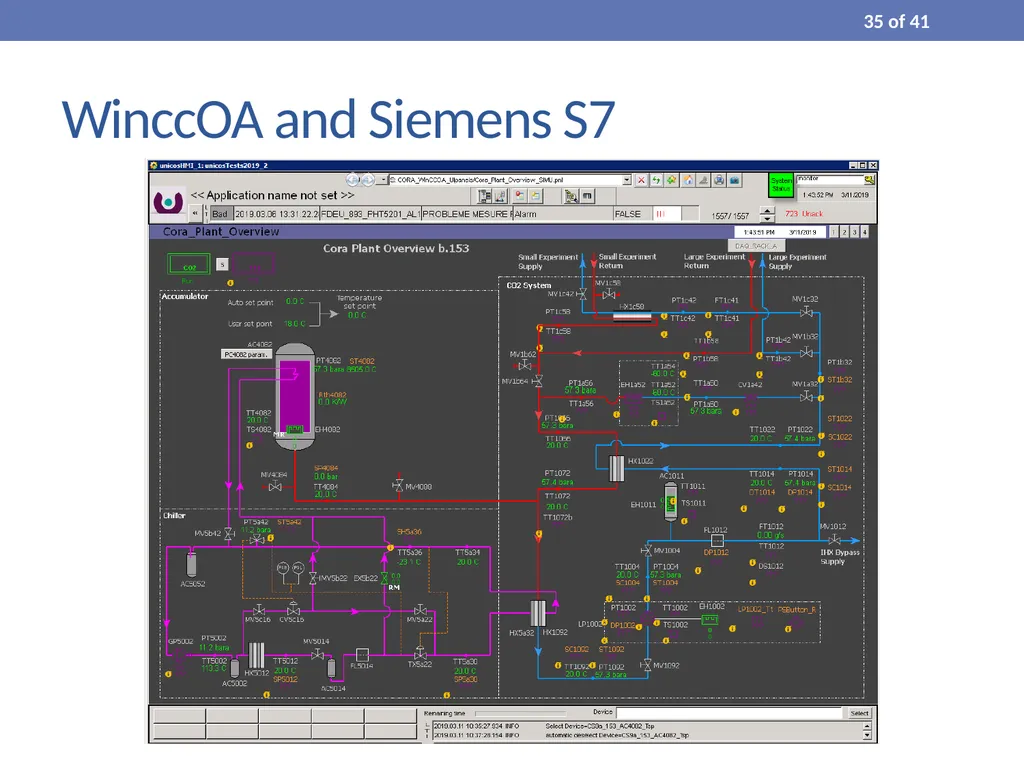
WinccOA and Siemens S7 35 of 41<br>
37
Project Status and Timeline 37 of 41<br>
38
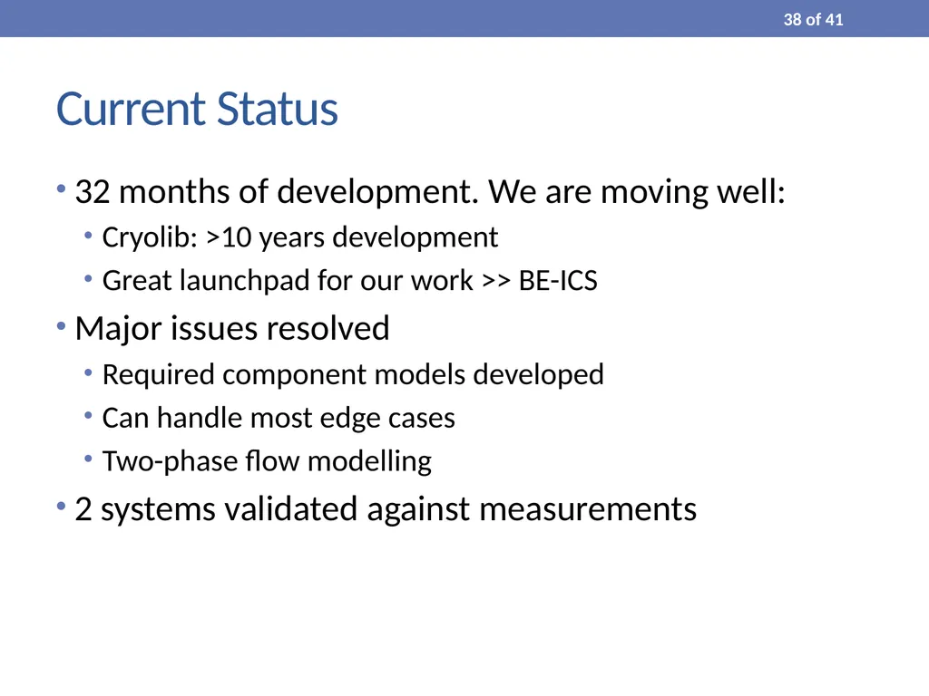
Current Status 32 months of development. We are moving well:
Cryolib: >10 years development
Great launchpad for our work >> BE-ICS
Major issues resolved
Required component models developed
Can handle most edge cases
Two-phase flow modelling
2 systems validated against measurements 38 of 41<br>
39
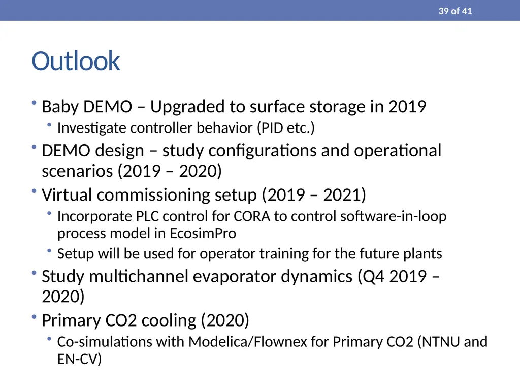
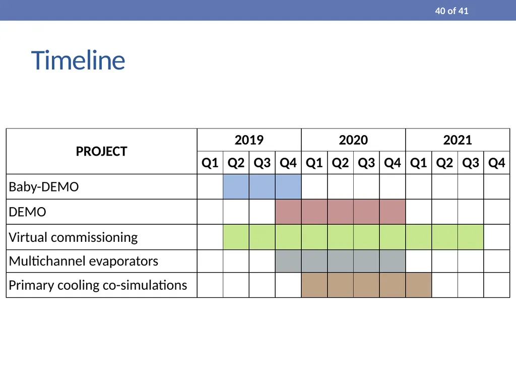
Outlook Baby DEMO – Upgraded to surface storage in 2019
Investigate controller behavior (PID etc.)
DEMO design – study configurations and operational scenarios (2019 – 2020)
Virtual commissioning setup (2019 – 2021)
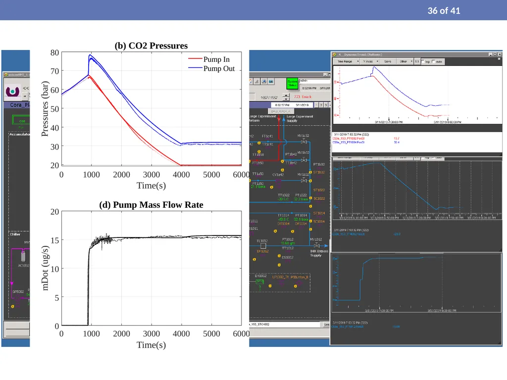
Incorporate PLC control for CORA to control software-in-loop process model in EcosimPro
Setup will be used for operator training for the future plants
Study multichannel evaporator dynamics (Q4 2019 – 2020)
Primary CO2 cooling (2020)
Co-simulations with Modelica/Flownex for Primary CO2 (NTNU and EN-CV) 39 of 41<br>
41
Questions Thank you for your attention 41 of 41<br>
42
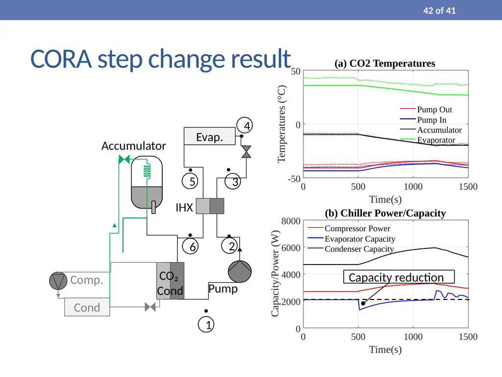
CORA step change result Capacity reduction 42 of 41<br>