/
Obtaining higher characteristic impedance from a 50 ohm cable by the insertion of inductors Obtaining higher characteristic impedance from a 50 ohm cable by the insertion of inductors

Obtaining higher characteristic impedance from a 50 ohm cable by the insertion of inductors - PowerPoint Presentation

alis
alis . @alis
Follow
68 views
Uploaded On 2023-11-09

Obtaining higher characteristic impedance from a 50 ohm cable by the insertion of inductors - PPT Presentation

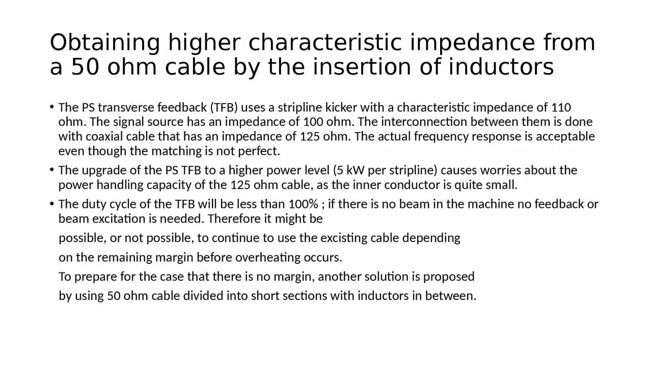
The PS transverse feedback TFB uses a stripline kicker with a characteristic impedance of 110 ohm The signal source has an impedance of 100 ohm The interconnection between them is done with coaxial cable that has an impedance of 125 ohm The actual frequency response is acceptable even though th ID: 1030819

cable filter order frequency filter cable frequency order ohm response impedance inductors capacitance cut length 100 line higher sections

Share:

Link:

Embed:

Download Presentation from below link

Download Presentation The PPT/PDF document "Obtaining higher characteristic impedanc..." is the property of its rightful owner. Permission is granted to download and print the materials on this web site for personal, non-commercial use only, and to display it on your personal computer provided you do not modify the materials and that you retain all copyright notices contained in the materials. By downloading content from our website, you accept the terms of this agreement.


Presentation Transcript

1. Obtaining higher characteristic impedance from a 50 ohm cable by the insertion of inductors The PS transverse feedback (TFB) uses a stripline kicker with a characteristic impedance of 110 ohm. The signal source has an impedance of 100 ohm. The interconnection between them is done with coaxial cable that has an impedance of 125 ohm. The actual frequency response is acceptable even though the matching is not perfect.The upgrade of the PS TFB to a higher power level (5 kW per stripline) causes worries about the power handling capacity of the 125 ohm cable, as the inner conductor is quite small.The duty cycle of the TFB will be less than 100% ; if there is no beam in the machine no feedback or beam excitation is needed. Therefore it might be possible, or not possible, to continue to use the excisting cable depending on the remaining margin before overheating occurs. To prepare for the case that there is no margin, another solution is proposed by using 50 ohm cable divided into short sections with inductors in between.

2. Increasing the impedance with inductors.The idea that the impedance of a transmission line can be increased by the addition of inductors in series with the line is not new. It was done for telephone lines to decrease the losses on long distance lines before amplification of the signals was possible (by Pupin).The connection between the signal source and the kicker has a relatively short lenghth, and all the connections between the kicker tank and the source / load can be made of equal length.Knowing the lenght of the cable, we then also know the capacitance of that cable from the pF/m given in the data sheet for that cable.

3. What is the best way to divide the cable in shorter sections ?When Pupin developed his technique, he made all sections equal (called constant K). The frequency response is not ideal.It is better to include the sections in a low pass filter of a given type that can be specified to have a defined frequency response.Comparison between the Butterworth, Bessel and Chebyshev filter types shows that for a given cut-off frequency, the Chebyshev type has the highest value of capacitance between the inductors, and therefore this translates in the longest section of cable. It is assumed that the cable behaves like a capacitor when it is short compared to the wavelenghts used, although the simulation shows that this is not entirely true.

4. Isn’t the Chebyshev filter bad ?The Chebyshev filter is know to have a peak in the group delay near the edge of the pass band. By making the cut-off frequency higher than the bandwidth requirements of the system , the peak will not be very high in the pass band.The Chebyshev filter can be specified to have a given amount of ripple over the whole passband. Low ripple also means low reflection coefficients up to the cut-off frequency, whereas other filter types have a slow roll-off at the edge of the passband and higher reflection coefficients. (passive filters work by reflecting the frequencies that are to be attenuated)

5. What has to be the order of the filter ?Whereas for the design of a low pass filter usually the cut-off frequency and the order of the filter are specified, here the design rule is quite different. The total capacitance in the filter has to be equal to the capacitance of the length of cable that it replaces.Therefore, first the characteristic impedance of the filter is specified.Then choose an order of the filter and a cut-off frequency that is convenient, for instance 100 MHz.Calculate the filter, and add up all the capacitors in the filter.Now normalize the total capacitance to be equal to that of length of cable to be replaced.( and also the inductors)With the values of components after normalisation, compute the frequency response of the filter. If it meets the requirements, cut the cable into sections that have the same capacitance as the capacitors in the filter. Add the inductors and the job is done.If the result is unsatisfactory, increase the order of the filter. Odd order with capacitor input is the most economical with inductors (usually the parts to minimise).

6. A few examples.With the ELSIE software, design a third order low pass filter.Arbitrarily, define cut-off at 100 MHz and ripple 0.2 dBThis filter has a total capacitance of 39.074 pF

7. Obtaining the filter that replaces 1.2 m of cableA type of coaxial cable that we want to use has 95 pF/mWe want a length of 120 cm, therefore C= 95 x 1.20 = 114pFThe filter that was calculated has 39.074 pF. The 114 pF divided by 2 becomes 57 pF. Replace the capacitors in the filter by 57 pF and multiply the inductor by 57/39.04 = 1.46. L then becomes 183.433 x 1.46 = 267.819 nH.Substitute these values in the circuit diagram and calculate the frequency response.

8. The third order filter and its response.

9. Fifth order filter and it’s response.The previous page showed that the requirement of a 60 MHz bandwidth could not be met. Lets try order 5. The total capacitance is now 77.1096 pF. To replace 114 pF of cable, multiply all elements with 114/77.1096. (right side circuit). Calculate response.

10. Order 5 LC filter response

11. Getting the cable lengthsLet’s assume that the frequency response meets the requirements. If not, the order has to be increased to 7 or more.The capacitances that were found are 31.5167, 50.9666 an 31.5167 pF. The total is 114 pF which is equal to 120 cm of cable. (or 95 pf/m)31.5176/95 = 0.33176 (2x) , 50.9666/95 = 0.53649, sum = 1.2 m.Now in the ELSIE program replace the capacitors with these lengths of 50 ohm cable. You will have to enter the length in electrical degrees. At 100 MHz the wavelength is 3m, divide the cable length by this value and multiply by 360 to get degrees.

12. Capacitors replaced by transmission line.

13. Left C and L Right T-line and L

14. ConclusionIt is possible to make a transmission line with an impedance higher than 50 ohm by adding inductors in series.The calculated LC low pas filter and the equivalent where the capacitors have been replaced with transmission line sections do not have identical frequency responses, but the difference is small and the group delay is actually better with the transmission lines.If the specifications on gain or group delay cannot be met, the order must be increased. This results in a higher cut-off frequency and better group delay. The complexity, however, increases.Not shown here but discovered accidentily is the fact that even order Chebyshey filters have non-identical input and output impedance, depending on the specified ripple. This could be an advantage to match the TFB kicker ,which is 110 ohm, to the source and load that are 100 ohm.

15. Simulated step and burst, 2 lines with kicker in between