/
x0000x0000IOWA DOT  BRIDGES AND STRUCTURES BUREAU LRFD BRIDGE x0000x0000IOWA DOT  BRIDGES AND STRUCTURES BUREAU LRFD BRIDGE

x0000x0000IOWA DOT BRIDGES AND STRUCTURES BUREAU LRFD BRIDGE - PDF document

alyssa
alyssa . @alyssa
Follow
344 views
Uploaded On 2021-06-08

x0000x0000IOWA DOT BRIDGES AND STRUCTURES BUREAU LRFD BRIDGE - PPT Presentation

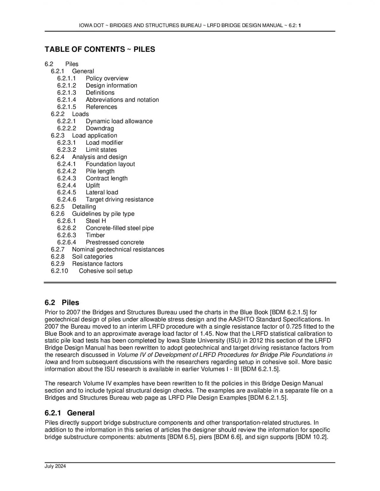
TABLE OF CONTENTS PILES62Piles621General6211Policy overview6212 62PilesPrior to 2007 the Bridges and Structures Bureauused the charts in the Blue Book BDM 6215 for x0000x0000IO ID: 837718

piles pile x0000 resistance pile piles resistance x0000 design bdm designer soil lrfd iowa driving table construction load soils

Share:

Link:

Embed:

Download Presentation from below link

Download Pdf The PPT/PDF document "x0000x0000IOWA DOT BRIDGES AND STRUCTUR..." is the property of its rightful owner. Permission is granted to download and print the materials on this web site for personal, non-commercial use only, and to display it on your personal computer provided you do not modify the materials and that you retain all copyright notices contained in the materials. By downloading content from our website, you accept the terms of this agreement.


Presentation Transcript

1 ��IOWA DOT ~ BRIDGES AND S
��IOWA DOT ~ BRIDGES AND STRUCTURES BUREAU~ LRFD BRIDGE DESIGN MANUAL ~ 6.2: �� February 2021 TABLE OF CONTENTS ~ PILES6.2Piles6.2.1General6.2.1.1Policy overview6.2.1.2 6.2PilesPrior to 2007 the Bridges and Structures Bureauused the charts in the Blue Book [BDM 6.2.1.5] for ��IOWA DOT ~ BRIDGES AND STRUCTURES BUREAU~ LRFD BRIDGE DESIGN MANUAL ~ 6.2: �� February 2021 6.2.1.1Policy overviewAlthough the Bureauuses a variety of foundation types depending on site and design conditions, the Bureaumost often selects pile foundations. Since the 1960s the Bureauhas recognized the benefits of jointless bridges with integral abutments. Integral abutments for bridgesof typical lengths require the lateral flexibility of pile foundations. Through experience with several pile types the Bureauhas determined that steel Hpiles provide flexibility, as well as adequate capacity for reasonable driven engths under typical Iowa site conditionsThen, for construction efficiency and costit often is appropriatalso to use steel Hpilesfor pierfoundations.However, in some cases there are other considerations for pile selection.For relatively short bridges where site conditions permit, the designer is encouraged to considertreatedtimber piles. For site conditions that favor displacement piles and also for pile bents without fully encased piles the designer is encouraged to consider prestressed concrete piles. Appropriateile choices for typical substructure components are summarized in Table 6.2.1.1.Table 6.2.1.1. Pile choices for support of substructure components Substructure Component Pile Choices Integral abutment Steel H P 10x57 for PPCB, CWPG , and RSB bridges, HP 1 0x42 for CCS bridges; timber for brid ge lengths to 200 feet Semi - integral and Stub abutment s St eel HP; timber; 12 inch prestressed concrete Pier St eel HP; timber; 12 inch prestressed concrete, concrete - filled steel pipe Pile bent [OBS SS P10L] Steel H P; 14 or 16 inch prestressed concret e, 14 or 16 inch concrete - filled steel pipe As indicated in the table, for typical design conditions the Bureaurecommendsthe HP 10x57shape when using steel Hpiles for integral abutments for pretensioned prestressed concrete beam (PPCB),continuous welded plate girder (CWPG), and rolled steel beam (RSB)bridges [BDM 6.5.1.1.1]. When using steel Hpiles for integral abutments for continuous concrete slab (CCS)bridges and for support of other substructurecomponents the Bureauprefers the HP 10x42shape. To avoid construction errorsthe Bureaurecommendsthat only one of the two HPshapes be used on eachproject.For driven piles the overall pile design, contract, and construction process followed by the Iowa Department of Transportation is as follows.The processis modified when one or more of the steps are performed by consultants.The Soils Design Unitarranges for soil borings and prepares a soilsdesignpackage for a bridge project.Based on the soils design package, designers in

2 the Bridges and Structures Bureauprepare
the Bridges and Structures Bureauprepare the bridge foundation design with an estimated contract length of piling.Contractors bid oninstallation of the contract length, with the expectation that all of the length will be driven even if bearing is obtained at shorter pile lengths.The Construction and Materials Bureauprepares WEAP driving graphs based on the successful contractor’s pile driving hammer.Inspectors from the Construction and Materials Bureauobserve pile drivingusing the WEAP driving graphs, prepare logs of the driving, and make fieldadjustmentssuch as retaps and extensionsneeded during pile installation.In generalthere are the following pile design considerationsunder LRFDfor the Soils Design Unitand the Bridges and Structures BureauAxial compression resistance at the strength limit stateDowndrag loads at the strength limit state for embankments that will have significant settlement after piles are driven for abutments, ��IOWA DOT ~ BRIDGES AND STRUCTURES BUREAU~ LRFD BRIDGE DESIGN MANUAL ~ 6.2: �� February 2021 Column resistance at the strength limit state for unsupportedpiles above ground, piles in prebored holes,or piles in scour conditions,Axial tension resistance at the strength limit state,Lateral load resistance at the strength limit state,Geotechnical resistance at the strength limit state,Target driving resistance at the strength limit state,Construction control method, if wave equation analysis (WEAP) is not appropriateSettlement at the service limit state,Lateral movement at the service limit state, Overall stability at the service limit state,Redundant group vs. single pile resistanceDesign and checkscour at piers,andCollision, ice,or seismic loads at the extreme event limit stateNot all these design considerations apply to each foundation pile group. For many pile groups only the axial compressionresistance, geotechnical resistance, target driving resistance, and construction control methodneed to be considered, but the designer shouldbe aware of allthe considerationsand check all that applyIn generalthe Bureaubases structural designon the AASHTO LRFD Specificationsand bases geotechnical design and pile driving designon recent Iowa State University researchand LRFD calibration. TheBridges and Structures Bureaurelies on the Iowa DOT Soils Design Unitfor a soils design package consisting of site informationgeotechnical analysis, and foundation recommendations and relies on theIowa DOT Construction and Materials Bureaufor WEAP analysis(the usual construction control)and pile driving inspectionFor structural design there are twoconditions that must be satisfied: pile axial resistance down to the tip and pile column resistance for piles without continuouslateral support above ground,in prebored holesor above scour elevation. For these structuralconditions the AASHTO LRFD Specifications provide the appropriate resistance factors and analysis information needed for design, but this manual section and the abutment and pier sections provide design s

3 implifications for typical bridgesOn mos
implifications for typical bridgesOn most Iowa bridge sites, piles derive their loadsupporting capacity from both friction and end bearing although, depending on site soil conditions, it is possible to design for either frictionbearingor end bearing. In cases where the designer intends to use end bearing in a soil layer, piles should be driven into the layer a sufficient amount to develop the end bearing resistancebut not so faras to risk punching into a weaker lower layer. In cases where piles bear on rock they should be driven to seat in the rock.For typical pile foundations the designer will need to estimate contract length and determine targetdriving resistanceat end of drive (EOD) and at one or more potential times for retaps. Determining these values at the strength limit state will require use of the following information given in this section:General soil categories [BDM 6.2.8],ominal unit geotechnical resistances extrapolatedfrom the Blue Book [BDM 6.2.7],Geotechnical resistance factors [BDM 6.2.9], andSetup factors for cohesive soil [BDM 6.2.10].The third and fourth items depend on the general soil category and the construction control method. For the ISU LRFD statistical calibrationused to determine geotechnical resistance factorspile load tests were categorized based on soil type in contact with length of pile using a 70% rule. If 70% or more of the pile length in contact with soil was againstcohesive soil, the soil category was defined as cohesive.70% or more of the pile length in contact with soil was againstnoncohesive soil, the category was defined as noncohesive. Otherwise the category was defined as mixed.The designer then must use these three soil categories when selecting resistance factors. Because prebored holes, downdrag, scour, excavation, and pile extensions in the field affect pile length in contact with soil, the soil category may change depending on the design or construction condition, in which case the designer will need to apply different resistance factorsas neededBecause of the step up or down in resistance factors at changes in soil category the designer will need to use judgment in unusual cases. ��IOWA DOT ~ BRIDGES AND STRUCTURES BUREAU~ LRFD BRIDGE DESIGN MANUAL ~ 6.2: �� February 2021 The ISU LRFD statistical calibrationfor geotechnical resistance factorsalso considered different construction control methods. For typical Iowa DOT projectsthe construction control method is wave equation analysis (WEAP). In special cases and when there is potential economy in more accurate control, the designer may consider PDA/CAPWAP, planned retap at threedays, or static pile load test, but all these special controls must be approved by the supervising UnitLeader. County and city agencies have the option of construction control by the traditional Iowa DOT ENR Formula (modified for LRFD)[IDOT SS 2501.03, M, 2]In cohesive soilsetup increases the friction bearing resistance of a pile after end of drive (EOD. The ISU LRFD statistical calibration deter

4 mined the effect of setup for cohesive s
mined the effect of setup for cohesive soils, and that effect has been separated out for determining target nominal driving resistance when the general soil category is cohesive. For mixed and noncohesive soil categories the setup will be much smalleror negligible, and setup does not need to be considered separately.The Iowa State University research and LRFD statistical calibration did not cover all driven pile design and construction conditions. For the conditions notcovered, such as prestressed concrete and pipe piles, end bearing on rock, tension piles, and lateral loading, the Bureauhas made policy decisions considering experienceand the AASHTO LRFD Specifications.For relatively light lateral loading the designer may use assumednominal resistances given in subsequent article[BDM 6.2.6.1, 6.2.6.3, for greater capacities, the designermay perform ananalysiswith consideration of soilloaddeformation response, pilematerialcross section, deflection, and strength criteriaThe designer mayconduct the analysiswith engineering software such as LPILE6.2.1.2Design informationThe soils design package provided for each bridge site by the Soils Design Unitcontains the soil logs ded for pile design [BDM 6.1.2] and location ofthe borings.Embankment fills are not typically inplace prior to the soil investigation for new structures. Generallythis means fill type and SPT Nvalues for the fill are unknown making it difficult to determine friction values for the piling. The Soils Design Unitprovides the following suggested properties if the specific fill properties are unknown:Embankments are commonly constructed with cohesive Class 10 material which could generally be classified as a Firm Silty Clay or similar material with a blow count of 11 bpf.Granular embankments are much less common, but for those constructed one may assume fine sand with a blow count of 15 bpf.Designers may contact the Soils Design Unitif additional information is required.For specification, material, or construction information beyond the information in this manual, the designer should consult the following sources. The most update versions of the publications are availablethe Iowa Department of Transportation web sitein the Electronic Reference Libraryhttp://www.erl.dot.state.ia.us, except the last item which is available from the Construction and Materials Bureauweb siteContracts and Specifications BureauStandard Specifications for Highway and Bridge Construction, Articles 2501, 4165, 4166, and 4167(http://www.iowadot.gov/erl/current/GS/Navigation/nav.htmConstruction and Materials Bureau, Instructnal Memoranda, 467, 467.01, 467.03, and 468http://www.iowadot.gov/erl/current/IM/navigation/nav.htmConstruction and Materials BureauConstruction Manualhttp://www.iowadot.gov/erl/current/CM/Navigation/nav.htmConstruction and Materials BureauNew Bridge Construction Handbookhttp://www.iowadot.gov/construction/structures/bridge_construction_handbook.pdf ��IOWA DOT ~ BRIDGES AND STRUCTURES BUREAU~ LRFD BRIDGE DESIGN MANUAL ~ 6.2: �

5 � February 2021 6.2.1.3Definition
� February 2021 6.2.1.3DefinitionsIowa DOT ENR Formulain this article and its commentary refers to four LRFD versions of the traditional pile driving formula in the Iowa DOT Standard Specifications [Iowa DOT SS 2501.03, M, 2]. The four versions cover different hammer and pile types. he Iowa DOT Standard Specifications were revised in 2013 to he LRFD versionsof the formulaand nowhave a constant in the numerator of the first term equal to 12 or larger.Natural ground elevationis the average natural ground elevation along the longitudinal centerline of the foundation.See the commentary for this article for discussion [BDM C6.2.1.3].Redundant pile groupis a minimum of five piles for all substructure components except abutments. For abutments a redundant pile group is defined by the Bureaua minimum of four piles.Retap(or restrike) occurs when a pile previously driven is hammered again after a time period, usually at ast 24 hours. Specific instructions for retapsintended to achieve geotechnical pile resistanceare given in the Standard Specifications [IDOT SS 2501.03, M, 5].6.2.1.4Abbreviations and notationCCS, continuous concrete slabCMP,corrugated metal pipeCWPG,continuous welded plate girderEOD, end of driveSETUPsetup factor [BDM 6.2.10]ISU,Iowa State Universitythickness of soil layer [BDM 6.2.10]LRFD,load and resistance factor designMSE,mechanically stabilized earth60or value, standard penetration test number of blows per footcorrected to a hammer efficiency of also may be given as SPT 60valueThe Iowa DOT is in the process of changing ecifications and determining hammercalibrations so that Nvalues will be reported. Until N60values are available the designer may follow past practice and use uncorrected Nvalues. See the commentarydiscussion[BDM C6.2.1.4].average 60valuefor use with setup chart [BDM 6.2.10]PPCB,pretensioned prestressed concrete beamΣηγQ/φrelationship for determining minimum pile length to resist uplift.Individual variables are defined in a subsequent article [BDM 6.2.4.4(ΣηγQ + )/φTARrelationshipfor determining target driving resistance.Individual variables are defined in a subsequent article [BDM 6.2.4.6].RSB,rolled steel beamSRL,structural resistance level. Four umbered levels are defined in the Hpile article [BDM 6.2.6.1].ΣηγQ + ≤ φRbasic LRFDgeotechnical checkwith downdragfor a timber, steel H, prestressed concrete,or concretefilled steel pipe pile. Individual variables are defined in a subsequent article[BDM 6.2.4.3ΣηγP≤ basic LRFDstructural check in the ground for a steel HpileIndividual variables are definedin a subsequent article[BDM 6.2.6.1]ΣηγP≤ basic LRFDstructural check in the ground for a timber pileIndividual variables are defined ina subsequent article[BDM 6.2.6.3]6.2.1.5ReferencesAbdelSalam, S.S.,K.W. Ng, S. Sritharan, M.T. Suleiman, and M. RolingDevelopment of LRFD Procedures for Bridge Pile Foundations in Iowa Volume III: Recommended Resistance Factors with Consideration of Construction Control and SetupAmes:Institutefor Transportation

6 , Iowa State University, 2012(Available
, Iowa State University, 2012(Available on the Internet at: http://www.intrans.iastate.edu/research/documents/researchreports/lrfd_vol_iv_final_w_cvr.pdfDirks, Kermit and Patrick Kam. Foundation Soils Information Chart, Pile Foundation. Ames: Iowa Department of Transportation, Design Bureau, January 1989/September 1994. (a.k.a. Blue Book ��IOWA DOT ~ BRIDGES AND STRUCTURES BUREAU~ LRFD BRIDGE DESIGN MANUAL ~ 6.2: �� February 2021 Generally with the move to LRFDthe ASDbased Blue Book is outdate, and its contents have been revised and moved to the BDMBlue Bookis available from theSoils Design Unitof the Office of DesiGAI Consultants, Inc. The Steel PilePile Cap Connection.Washington, DC: American Iron and Steel Institute (AISI). 1982.(Contact AISI for a reprint, for which there is a charge.)Green, D., K.W. Ng, K.F. Dunker, S. Sritharan, and M. Nop. Development of LRFD Procedures for Bridge Pile Foundations in Iowa Volume IV: Design Guide and Track Examples.Ames: Institute for Transportation, Iowa State University, 2012. (Available on the Internet at: http://www.intrans.iastate.edu/research/projects/detail/?projectID=700958271Hannigan, P.J., G.G. Goble, G.E. Likins, and F. Rausche. Design and Construction of Driven Pile FoundationsVolumes I and II,FHWANHI05042.Washington, DC: National Highway Institute, Federal Highway Administration, 2006Iekel, P.P., B. Phares, and M. Nop. Performance Investigation and Design of PileToPile Cap Connections Subject to Uplift (Expanded). Ames: Institute for Transportation, Iowa State University, 2017Ng, K.W., M.T. Suleiman, M. Roling, S.S. AbdelSalam, and S. Sritharan. Development of LRFD Procedures for Bridge Pile Foundations in Iowa Volume II: Field Testing of Steel HPiles in Clay, Sand, and Mixed Soils and Data Analysis.Ames: Institute for Transportation, Iowa State University, 2011. (Available on the Internet at:http://publications.iowa.gov/13626/Bridges andStructures Bureau. “LRFD Pile Design Examples ~ 2016”. Ames: Bridges and Structures Bureau, Iowa Department of Transportation, 2016Construction and Materials BureauConstruction Manual.Ames: Construction and Materials BureauIowa Department of Transportation, 2008. (Available on the Internet at: http://www.iowadot.gov/erl/current/CM/Navigation/nav.pdfConstruction and Materials BureauPile Points for Steel HPiles, Instructional Memorandum 468Ames: Construction and Materials Bureau, Iowa Department of Transportation, October 2011. (Available on the Internet at:http://www.iowadot.gov/erl/current/IM/navigation/index_number.htmConstruction and Materials BureauSteel HPiles, Instructional Memorandum 467.01.Ames: Construction Materials Bureau, Iowa Department of Transportation, October 2011. (Available on the Internet at: http://www.iowadot.gov/erl/current/IM/navigation/index_number.htmConstruction and Materials BureauSteel Piles, Instructional Memorandum 467.Ames: Construction and Materials Bureau, Iowa Department of Transportation, October 2011. (Available on the Internet at: http:/

7 /www.iowadot.gov/erl/current/IM/navigati
/www.iowadot.gov/erl/current/IM/navigation/index_number.htmConstruction and Materials BureauWelded and Seamless Steel Pipe Piles, Instructional Memorandum 467.03.Ames: Construction and Materials Bureau, Iowa Department of Transportation, October 2011. (Available on the Internet at: http://www.iowadot.gov/erl/current/IM/navigation/index_number.htmRoling, M., S. Sritharan, and M. Suleiman. Development of LRFD Procedures for Bridge Pile Foundations in Iowa Volume I: An Electronic Database for Pile Load Tests in Iowa (PILOTIA).Ames: Institute for Transportation, Iowa State University, 2010. (Available on the Internet at: http://publications.iowa.gov/13624/Sunday, Wayne and Kyle Frame. New Bridge Construction Handbook.Ames: Construction and Materials Bureau, Iowa Department of Transportation, 2000. (Available on the Internet at: http://www.iowadot.gov/construction/structures/bridge_construction_handbook.pdf ��IOWA DOT ~ BRIDGES AND STRUCTURES BUREAU~ LRFD BRIDGE DESIGN MANUAL ~ 6.2: �� February 2021 6.2.2LoadPile loadsmust be considered with respect to the substructure component supported by the piles. Abutment and pier articles [BDM 6.5 and 6.6] cover additional load topics, and the designer should review ose articles in addition to the articles below.For standard abutment, footing, and pile cap details the Bureauassumes axial vertical loads transmitted to piles. If nonstandard pile head details cause significant eccentricityor moment, the designer shalconsider those effectsin design.Whenlateral loads are applied to piles the designer shall consider both lateral forces and lateral displacements[BDM 6.2.4.5].6.2.2.1Dynamic load allowance[AASHTOLRFD 3.6.2.1The AASHTO LRFD Specifications [AASHTOLRFD .6.2.1notethat the dynamic load allowance(IM) need notbe applied to foundation components that are entirely below ground leveland in full contact with soilAs a conservative design simplification, the Bureaurequires the designer to include the dynamic load allowancefor the entire length of a pile that has a portion unsupported by soil, such as a pile in a pile bent or an integral abutment pile in a prebored hole filled with bentonite slurry.However, the designer shall not include the dynamic load allowanceon a stub abutment pile in a prebored hole.Because scour generally is a temporary condition the designer also should not include dynamic load allowance on a pile being checked under scour conditions.6.2.2.2DowndragDowndrag generally occurs at abutments when placement of approach fill causes settlement of compressible soils below the fill. Downdrag may be avoided if the embankment can be placed a sufficient time before abutment piles are driven and, in that case, the designer shall include CADD Note E175/M175 [BDM .3.2] on the plans with a minimum time period determined by the Soils Design UnitIf abutment piles must be placed before the approach fill settlement has occurred, the designer shalconsider downdrag forces as directed by the Soils Design Unitor soils that are labeled comp

8 ressible in the soils package for the br
ressible in the soils package for the bridge project.Downdrag forces are caused by negative skin frictionand add to the pile loads, as well as eliminate positive friction bearing in the downdrag zone. Downdrag forces may be reduced by use of prebored holes with bentonite fill.Large downdrag forcesat abutments with steel Hpiles designed for Structural Resistance Level 1(SRL1) [BDM 6.2.6.1] often require significantly more piles or larger piles than similar abutments which not need to be designedfor downdrag. In order to mitigate the effects of downdragon the number and/or size of steel Hpiles at abutments to some degreethe Bureauallows designers increase theSRLnominal structural resistancein BDM Table 6.2.6.1by %.The25% increaseappliedto SRLessentially creates SRL1.5 whichis halfway between SRL1 and SRL2. For example, the nominal structural resistance for a typical Grade 50 HP 10x57pile in BDM Table 6.2.6.11 would increase fromSRLvalue of243 kSRL1.5 value ofThe total factored axial compression load shall not exceed the factored structural resistance of SRL1 and the total factored axial compression load plus the factored downdrag load shall not exceedthe factored structural resistance of SRL1.5.Downdrag forces shall be determined from thenominal geotechnical resistance chart for friction bearing [BDM Table 6.2.7in accordance with policy in a subsequent article [BDM 6.2.4.3].Battered piles shall not be used if downdrag will occur. ��IOWA DOT ~ BRIDGES AND STRUCTURES BUREAU~ LRFD BRIDGE DESIGN MANUAL ~ 6.2: �� February 2021 6.2.3Loadapplication6.2.3.1Load modifier[AASHTOLRFD 1.3.2, 3.4.1]Load factors shall be adjusted by the load modifier, which accounts for ductility, redundancy, and operational importance [AASHTOLRFD 1.3.2, 3.4.1]. For typical pile foundations the load modifier shall be taken as 1.0.6.2.3.2Limit state[AASHTOLRFD 3.4.1, 3.4.2]For a typical pile foundation, the designer shall consider the following load combinationsfor the supported structural component, as applicable [AASHTOLRFD 3.4.1].For design of abutment foundations the designer should use judgment to exclude any cobinations that will not controlStrength I, superstructure with vehicles but without windStrength III, superstructure witdesign 3second gust wind speed at 115 mphStrength V, superstructure with vehicles and with design 3second gust wind speed at Extreme Event II, superstructure with reduced vehicles and vehicular collision, ice, or hydraulic eventsService I, superstructure with vehicles and with design 3second gust wind speed at mphIn general the designer need not investigate ServiceI limit stateunless settlement, lateral movement, or overall stability is a concern.verall stability willbe analyzed by the Soils Design UnitneededExcept for unusual situations, such as eccentric loads during staged construction, the designereed notinvestigate construction load combinations [AASHTOLRFD 3.4.2].Design of the pile foundation shall be based on the resulting critical combinations includingmaximum axi

9 al force, maximum moment, and maximum sh
al force, maximum moment, and maximum shear.6.2.4Analysis and designPile section and contract length shall be determined by the load and resistance factor design (LRFD) method as modified in this and other manual sectionconsidering structural resistance, geotechnical resistance,target driving resistance, and other design considerations applicable to the pile foundation design [BDM 6.2.1.1]Structural resistanceTo determine the required pile section and/or number of piles for typical pier and abutment design, the designer shall compare the factored axial load per pile or per pile group with the factored nominal structural resistance. Specific guidelines for structural design by pile type are given in a subsequent article [BDM 6.2.6], and guidelines for integral abutment piles are given in the abutment section [BDM 6.5.1.1.1]Piles that extend above ground such as those in pile bents either need to be selected in accordance with the P10L standard orneed to be checked structurally for the column conditionconsidering scourusing the guidelines given in this manual [BDM 6.6.4.2]Pier piles subject to scour need to be checked for the column condition below the footing [BDM 6.6.4.1.3.1].Geotechnical resistanceTo determine the required contract pile length the designershall compare the factored axial load per pile with the factored nominal geotechnical resistance determinedfrom thecharts [BDM Table 6.2.71 and 6.2.7Geotechnical resistance factors are dependent on the method of construction control and are given after the charts [BDM 6.2.9]. Additional pile length guidelines are given below [BDM 6.2.4.1].ier piles subject to scour need to be checked for the loss of soil support [BDM 6.6.4.1.3.1].Target driving resistanceThe designer also shall determine the target nominal driving resistance based on the method of construction control, which usually will be WEAP for state projects[BDM 6.2.4.6]. Depending on the general soil type in contact with the pile, the designer also will need to specify one or more nominal retap resistances. ��IOWA DOT ~ BRIDGES AND STRUCTURES BUREAU~ LRFD BRIDGE DESIGN MANUAL ~ 6.2: �� February 2021 Specific steps in the overall design and construction processfor typical bridgesare outlined below and followed in design examples.The steps may be modified depending on Bureaupractice and bridge project.(1)Developbridge situation plan (or TS&L, Type, Size, and Location).(2)Developsoils package, including soil borings and foundation recommendations.(3)Determine pile layout, pile loadsincluding downdrag, and other design requirements. This stepincludestructural checks.(4)Estimatenominalgeotechnical resistance for friction and end bearing(5)Select resistance factor(s) to estimate pile length based on the soil profile and construction control.(6)Calculaterequired nominal pile resistance, R(7)Estimatecontract pile lengthconsidering downdrag, scour, pile upliftlateral loadin, and unbraced length,if applicable(8)Estimate target nominal pile driving resistance, Rndr(9)Pre

10 pareCADD notes for bridge plans.(10)Chec
pareCADD notes for bridge plans.(10)Check the design.(11)Request and check contractor’s hammer data, and prepare bearinggraph for WEAP control or other necessary items for alternate methods of construction control.(12)Observe construction, record driven resistance, and resolve any construction issues.6.2.4.1Foundation layout[AASHTOLRFD 10.7.1.2For each foundation the designer should attempt to use the minimum number of piles required for structural support. Individual pile layouts for each foundation are preferredfor typical bridges, and the designer should not add extra piles to replicate foundationsunless there is a definite advantage such as cost and/or time savings for accelerated bridge constructionThe maximum centerline pile spacing for abutments and pile bents shall be 8 feetThe minimum centerline pile spacing shall bethe larger of 2.5 feetor 2.5 times the pile size [AASHTO LRFD 10.7.1.2]. Based on soil conditions and additional guidelines below, piles shall be spaced at a centerline distance that does not exceed the maximum or minimum limits. The minimum centerline distance to a footingshall be 1.5 feetThe minimum number of piles for an integral abutment shall be one pile per beam plus one pile per wing extension. For integral abutments the Bureaurequires that all piles be driven vertically, but for all other substructure elements the designer should batter some of the piles as indicated on standard sheets. emiintegral abutmentsare typicallysupported on two rows of pilesbattered outward at1 horizontal to 6 vertical slope (1:6 batter)however designermay elect to design semiintegral abutments with a single row of vertical pilesTypicallythe front row and wing wall piles for stub abutments, the perimeter piles for frame or Tpier footings, and the end piles for pile bents should be battered. The preferred batter for stub abutments and piers is 1:4, with 1:6as an acceptable alternative, and the preferred batter for pile bents is 12. Normally battered piles shall be oriented such that any soil settlement will be resisted by strongaxis ��IOWA DOT ~ BRIDGES AND STRUCTURES BUREAU~ LRFD BRIDGE DESIGN MANUAL ~ 6.2: �� February 2021 pile bending. The designer shall check battered piles for interference with temporary structures such as cofferdams, as well as for permanent obstructions such as utility lines and foundations.When a mechanically stabilized earth (MSE) retaining wall is placed in front of integral abutment piles, the piles typically are to be sleeved with corrugated metal pipe (CMP). For compaction of the fill between the sleeves and placement of the metal strip reinforcing for the wall, a minimum sleeve clear distance of 24 inchesis preferred. With the typical 24inchdiameter CMP and a 24inch clear distance, the centerline pile spacing will be 4 feet. Therefore, the designer needs to consider the minimum pile spacing carefully for integral abutments behind MSE walls. For integral abutments the Bureaualso requires a minimum of 36 inchesclear between the

11 back of the MSE wall and the face of th
back of the MSE wall and the face of the CMP sleeves. The clearance is intended to permit compaction of the backfill, to avoid sharp angles in the reinforcing straps, and to prevent the bentonite in the CMP sleeves from freezing. For semiintegral and stub abutments the clear distance maybe less than 36 inches subject to requirements of the MSE wall vendor. When the MSE wall is built in two stages and/or when utility lines are in the backfill zone the designer shall determine clearances based on discussions with the MSE wall vendor. 6.2.4.2Pile length[AASHTOLRFD 10.7.1.3, 10.7.3.9In addition to the basic geotechnical resistance check at the strength limit state [BDM 6.2.4.3any applicable uplift considerations [BDM 6.2.4.4], and any applicable lateral load considerations [BDM 6.2.4.5], contract pile length will depend on various site and substructure factors. The design penetration for any pile should be a minimum of 10 feethard cohesive or dense granular soil and a minimum of feetsoft cohesive or loose granular soil. Piles driven through embankmentould penetrate 10 feetinto original ground unless refusal on bedrock or a competent layer occurs at a lesser elevation [AASHTOLRFD 10.7.1.3]. Piles subject to uplift shall be driven the minimum length to ensure adequate geotechnical tension resistancIn order to relieve stresses due to lateral movement, piles for integral abutments for bridges longer than 130 feet shall be driven in prebored holes. Abutment piles also may be driven in prebored holes to reduce downdrag due to settlement of the abutment berm. Guidelines for prebored hole depths are given in Table 6.2.4.Table 6.2.4.21. Prebored hole depths for abutments Abutment type Hole depth feet Comments Integral 10 (1) Standard depth Integral 15 Maximum depth without approval of supervising Unit Leader Semi - integral and Stub 20 Maximum depth without approval of supervising UnitLeader Table note: (1)If bedrock is less than 15 feet from bottom of footing, prebored hole depth may be reduced with consideration of bridge length, but the designer shall discuss the condition with the supervising UnitLeader. Pile length shall be determined so that the geotechnical resistance due to friction, end bearing, or a combination of friction and end bearing will be achieved below the lowest of the following elevations:Bottom of predrilled hole (abutments) [BDM Tables 6.2.4., 6.5.1.1.11, and 6.5.1.1.12],ttom of compressible fill when berm consolidation delays are not permissible(abutments)Bottom of pile encasement (pile bents) [BDM 6.6.4.2.2],Design scour elevation (piers) [BDM 6.6.4.1.3.1], orCheck scour elevation (piers) [BDM 6.6.4.1.3.1]. ��IOWA DOT ~ BRIDGES AND STRUCTURES BUREAU~ LRFD BRIDGE DESIGN MANUAL ~ 6.2: �� February 2021 Additional considerations for determining the pile length are the following.Natural or original ground elevation is the average natural ground elevation along the longitudinal centerline of the foundation.Heads of piles shall

12 be embedded in abutments, footings,bent
be embedded in abutments, footings,bent caps, and pier caps the length given in the pile detailing article [BDM 6.2.5].The heads of steel Hpiles, steel pipe piles, and timber piles shall be trimmed one footto account for driving damage.If fill is placed above a compressible soil layer,such as at an abutment, piles will be subjected to downdrag forces that need to be included in design.The bentonite slurry [IDOT SS 2501.03, Q] required for filling of a prebored hole for a pile shall be assumed to provide no vertical or lateral support to the pile. The slurry also shall be assumed to cause no downdrag forces.A pile battered no more than 1 horizontal to 4 vertical may be assumed to carry the same vertical load as a pile driven vertically; there need be no reduction for angle of the pile.If several pile types or sizes are feasible, the designer should discuss the alternatives with the supervising UnitLeader. Determining the best or most economical alternative involves pile availability and cost, driving equipment availability and cost, and structural factors.For steel Hpiles and timber piles, length shall be specifiedto the nearest 5footincrement. For prestressed concrete piles, length shall be specified to the nearest 1footincrement, except that pile extensions shall be specifiedto the nearest 5footincrement.To determine an end bearing resistance value [BDM Table 6.2.71] the designer should average the 60values over a distance eight feet above and below the pile tip.If a pile is designed with end bearing resistance in soil the pile shall be driven a minimum of 5 feetinto the layer. The designer also shall ensure that the pile tip will not punch through the bearing layer into a weaker layer.If an Hpile is designed with end bearing resistance in bedrock the pile should be driven with penetration as indicated in Table 6.2.4.2. Prestressed concrete and steel pipe piles should be driven to bedrock only with approval of the Soils Design Unit. Timber piles shall not be driven to bear on bedrock.Table 6.2.4.22. Recommended Hpile penetration into bedrock Rock classification Recommended penetration, feet Broken limestone 8 - 12 where practical Shale or firm shale 8 – 12 Medium hard shale, hard shale, or siltstone with 50 ㈀〰 匀慮摳琀潮攬⁳椀l琀猀琀潮攬爀⁳栀慬攠 睩琀栀⁎ ㈰  匀潬椀搠l椀浥猀琀漀湥 In the unusual case that a frame pier or Tpier pile foundationmeets all three of the following conditionsthe designer shall evaluate the axial friction resistance for the piles with the appropriate group efficiency reduction factor [AASHTO LRFD 10.7.3.9].(a)The footing is not in contact with the groundor sour may remove soil below the footing.(b)Piles are in cohesive soil and the soil near the surface belowthe footing has unconfinedshear strength less than 2 ksf(which approximately correlates with values less than 16(c)The footing has no battered pilesIf less than 1.0, the efficiency factor will increase pile length or require redesign of the fo

13 undationThe efficiency factor does not a
undationThe efficiency factor does not apply to typical integral abutments, stub abutments, pile bents, ��IOWA DOT ~ BRIDGES AND STRUCTURES BUREAU~ LRFD BRIDGE DESIGN MANUAL ~ 6.2: �� February 2021 frame pier foundations with battered piles, and Tpier foundations with battered piles(See the Commentary for this article for further information regarding this policy.)Pile group efficiencies in cohesive soil are known to be reduced for a time period after driving due to excess pore water pressure. If accelerated bridge construction (ABC) requires that piles in cohesive soil are loaded very soon after driving the designer shall investigate the need for lengthening piles or otherwise redesigning the foundation.6.2.4.3Contract length[AASHTO LRFD 10.7.3.9]Because resistance factors will vary with the method of construction control the designer will need to select the control methodbefore determining the pile contract length. The WEAP method is used for typical state projects, and Iowa counties and cities may use either WEAP or theIowa DOT ENR ormulamodified for LRFDFor large and specialprojects other methods of construction control are available[BDM 6.2.9]Contract pile length for downward load shall be determined byusing thesoil categories [BDM 6.2.8], LRFD nominal geotechnical resistance charts [BDM 6.2.7], and resistance factors [BDM 6.2.9]Depending on subsurface conditions, the pile resistance may be theaccumulated skin friction resistance through several soil layers,the end bearing resistance ina dense soil layer or rock, orthe accumulated skin friction resistance plus end bearing resistance in a dense soil layeror rockThe basic LRFD relationship used to determine the contract length for an individual pile is the following:Σηγ≤ φis rearranged for design to(ΣηγQ + )/φhere= nominal geotechnical resistancedetermined from unit valuesfor friction [BDM Table 6.2.72] and/or end bearing [BDM Table 6.2.71]. In the case of downdrag or scour the nominal resistance above the downdrag elevation or scour elevation shall be neglected.Forframe pier or Tpier pile foundationswith a gap below the footing, with piles in soft cohesive soil, andwithout battered piles [BDM 6.2.4.2], the designer shall multiply the nominalgeotechnicalfriction resistance(but not the end bearing resistance)by the appropriate group efficiency reduction factor [AASHTO LRFD 10.7.3.9].his caseor acase where piles in cohesive soil are spaced less than 2.5 diameters or 2.5 feetapartalso requiresthe designer to check the equivalent pier resistance[AASHTO LRFD 10.7.3.9].Σηγ= total factored axial compression load per pile determined by usual LRFD procedures for a strength limit state, kips. If the pile resistance is partially due to end bearing on rock the ΣηγQ term needs to be splitthat the fractiondue to end bearingis divided b= 0.70 and the fractiondue to friction bearingis divided by the appropriate from BDM Table 6.2.9The formula then becomes:ΣηγQ/0.70 + ΣηγQ/downdrag loadfactor = 1.0= downdrag

14 load.The load is determined from frictio
load.The load is determined from friction bearing values [BDM Table 6.2.72]. If there is no downdrag this term is taken as zero ��IOWA DOT ~ BRIDGES AND STRUCTURES BUREAU~ LRFD BRIDGE DESIGN MANUAL ~ 6.2: �� February 2021 = geotechnical resistance factor selected from information given in BDM Table 6.2.9for the site soil category and method of construction controlExamples for determining contract length are given in RFD Pile Design Examples ~ [BDM 6.2.1.5]. The Track 1 examples cover typical projects on the state highway systemwith WEAP construction controlTrack 2 examples cover local agency projects that useIowa DOT ENR Formula control. Track 3 examples cover special casesof construction controlthat may occur on large and unusual projects.After contract length and otherfeatures of design are determined the designer should communicate the design on the plans using CADD NotesE818 and E819 for abutment piles and E718 and E719 for pier piles[BDM 1.8]6.2.4.4UpliftUnder all limit states the designer may consider uplift on piles provided that piles are sufficiently anchored in the footing and have sufficient soilpile friction resistance for the uplift force. esistance between footing concrete and an Hpile and resistance factors are discussed in the steel Hpile article [BD6.2.6.1].The designer shall check the geotechnical resistance to uplift for piles in tension as follows:ΣηγQ/φWhere= nominal geotechnical resistancedetermined from unit valuesfor friction [BDM Table 6.2.7ΣηγQ= total factored axial tension load per pile determined by usual LRFD procedures for a strength limit state, kips.= geotechnical resistance factor selected from information given in BDM Table 6.2.92 for the site soil category and method of construction controlIf the check is successful the designer shall determine the minimum required length of pile to resist the uplift load and include that minimum lengthon the plansin the appropriate CADD Note, E819 or E719 [BDM 1.8.2]Track 1, Example 4 in RFD Pile Design Examples ~ 2016 [BDM 6.2.1.5] is written for a case that involves uplift on a steel Hpile.6.2.4.5Lateral load [AASHTOLRFD 10.7.2.4]For typical bridge piers and stub abutments supported on steel Hpiles or timber piles the designer may check lateral loading of piles at the service and strength limit states using traditional nominal resistances given in following articles [BDM 6.2.6.1, 6.2.6.3]. Piles in typical integral abutments that meet the conditions given in the abutment section [BDM 6.5.1.1.1] need not be checked for lateral load.If the checks using nominal values fail or if the pile conditions require further analysis, the Bureauprefers that the designer use the program LPILE or equivalent software to check deflection at the service limit state and moment and shear at the strength and extreme event limit state. Group effects shall be considered [AASHTOLRFD 10.7.2.4].If using LPILE to check pier or stub abutment piles for typical bridges, the designer may assume a maximum service limit stat

15 e lateral deflection of 0.25 inchfor a s
e lateral deflection of 0.25 inchfor a single pile or 0.75 inchfor a pile group. ��IOWA DOT ~ BRIDGES AND STRUCTURES BUREAU~ LRFD BRIDGE DESIGN MANUAL ~ 6.2: �� February 2021 Lateral deflection at the top of a pier should be limited to 1.50 inches. If these limits are exceeded the designer shall consult with the supervising UnitLeader.See the commentary for background discussion [BDM C6.2.4.5] and steel Hpile examples [BDM C6.2.6.16.2.4.6Target driving resistanceThe designer shall determine the target nominal driving resistance that will be used in the field to ensure adequate pile bearingresistance. In the case of cohesionless or mixed soilswith WEAP control[BDM 6.2.8]or all soils with Iowa DOT ENR Formula controla single target driving resistance shallbe used at end of drive (EOD) andfor retaps one or more days after EOD.(ΣηγQ + )/φTARWhere:= nominal target driving resistance at a defined time. ndris the target driving resistance at EOD; ndris the target driving resistance at one day, etc. For cohesionless and mixed soilwith WEAP control and all soils with Iowa DOT ENR Formula controlndrwill not vary with time: ndrndrndrΣηγQ= total factored axial compression load per pile determined by usual LRFD procedures for a strength limit state, kips.= downdrag load factor = 1.0= downdrag load. The load is determined from friction bearing values [BDM Table 6.2.72]. If there is no downdrag this term is taken as zeroTAR= target driving resistance factor selected from information given in BDM Table 6.2.93 for the site soil category and method of construction control.= nominal friction resistance for the soil that is subject to scour determined from unit values for friction [BDM Table 6.2.7In the case of piles and cohesive soilswith WEAP construction controle designer shall consider the benefit of setup in the determination of the target driving resistance except in the following cases:Piles driven to bedrock,Piles subjected to downdrag,Piles in contact with cohesive soil with an overall average N of less than 5, andPiles used in accelerated bridge construction.When setup is considered designers will need to determine multiple target driving resistances because setup will increase resistance with time.(Do not use this procedure for other pile types, mixed or cohesionless soils, or Iowa DOT ENR Formula construction control.)The setup increase, however, is limited by EODas indicated below.The relationship to determine target driving resistanceat EODfor piles and cohesive soilwith WEAP controlis as follows:(ΣηγQ + )/φTARWhereTARSETUPSETUP1) 1.0 ��IOWA DOT ~ BRIDGES AND STRUCTURES BUREAU~ LRFD BRIDGE DESIGN MANUAL ~ 6.2: �� February 2021 and are taken from BDM Table 6.2.93, and Fis taken from the 7day curve in Figure 6.2.10based on the average SPT60valuedetermined as discussed in BDM 6.2.10for retap at one daythe smaller of:(ΣηγQ + )/φEODSCOURSETUPWhere is taken from the 1day curve in Figure 6.2.10for retap at three days is the smaller of:(Σ

16 ηγQ + )/φEODSCOURSETUPWhere is taken
ηγQ + )/φEODSCOURSETUPWhere is taken from the 3day curve in Figure 6.2.10for retap at seven days is determined in a similar way.Forpileretaps in cohesive soils the first of the two retap quantities, which is not based directly on setup,often will limit the target driving resistance for all retaps one day and later.In that case the designer will need to specify only a nominal driving target for EOD and a second nominal driving target for retap at one or more days.In unusual cases the designer may need to specify three nominal driving targets, one for EOD, one for oneday retap, and one for threeday or more retap.Examples for determining target driving resistance are given in RFD Pile Design Examples ~ 2016 [BDM 6.2.1.5]. The Track 1 examples cover typical projects on the state highway system with WEAP construction control. Track 2 examples cover local agency projects that useIowa DOT ENR Formula control. Track 3 examples cover special cases of construction control that may occur on large and unusual projects.After target driving resistance and other features of design are determined the designer should communicate the design on the plans using CADD Notesas follows:Abutment notesE818 and E819[BDM 1.8.2],andPier notesE718 and E719 [BDM 1Except in unusual cases the pile driving sequence will be governed by the Construction and Materials Bureau’s Construction manual, Article 11.22.6.2.5DetailingPiles shall be embedded in substructure elements and shall have the head reinforcing listed in Table 6.2.5. ��IOWA DOT ~ BRIDGES AND STRUCTURES BUREAU~ LRFD BRIDGE DESIGN MANUAL ~ 6.2: �� February 2021 Table 6.2.5. Minimum pile embedment and pile head reinforcing Substructure element Minimum embedment Pile head reinforcing Integral abutment for A or B pretensioned prestressed concrete beams (PPCBs) 2 feet Spiral ( 1) Integral abutment for C , D , BTB, BTC, BTD, or BTEpretensioned prestressed concrete beams (PPCBs) 2 feet Spiral ( 1) and bent p bars (2 ) Integral abutment for steel plate girders 2 feet Spiral ( 1) (3) a nd bent p bars 2)(3) Stub abutment on timber piles 2 feet Spiral (3) Stub abutment on steel H - piles 2 f eet None (4) Frame pier or T - p ier footing 1 foot None (3) Continuous concrete slab pile bent cap (not monolithic with slab) 1.5 feet None (3) Continuous concrete slab pile bent cap (monolithic with slab) 1 foot Cap steel (bent dowels) (5 ) Table notes:(1)Spiral is placed around each pile head as detailed on standard sheets [OBS SS 2078The spiral should not be epoxy coated.(2)For the bent p bars see the Abutment Pile Plan on standard sheets [OBS SS 20852091(3)No standard sheet is available(4)See standard sheets for C or D beams [OBS SS 2092(5)Cap steel (bent dowels) is detailed on a standard sheet[OBS SS P10LFor pier footings with reinforcing placed directly above Hpile, pipe pile, or timber pile heads, plans shall include a note requiring that all battered piles

17 be trimmed to a horizontal line to aid
be trimmed to a horizontal line to aid in placement of reinforcement. Prestressed concrete piles should not be trimmed.For projects involving the Excavate and Dewater bid item the E832 (M832) ADD Note[BDM .8.2] shall be included on the plans.6.2.6Guidelines by pile typeFor information onselecting pile type for integral abutments see the guidelines in the integral abutment article [BDM 6.5.4.1.1].6.2.6.1Steel H[AASHTOLRFD 6.5.4.2, 10.5.5.3.3]Steel Hpiles are feasible in most Iowasoils and may attain geotechnical resistance through end bearing, frictionbearingor a combination of endand frictionbearingSteel Hpiles shall be of material meeting ASTM A 572/A 572M Grade 50[IDOT SS 4167.01, A, OM IM 467.01], unless an exception is approved by the supervising UnitLeader.The basic structural check for typical integral abutment, stub abutment,and pier iles is given below. The check represents an axial force condition at the bottomof apile, with consideration of the potential for driving damageΣηγP≤ nφΣηγP= total factored axial load per pile or per pile group determined by usual AASHTO LRFD procedures for a strength limit state, kips= downdrag load factor = 1.0 ��IOWA DOT ~ BRIDGES AND STRUCTURES BUREAU~ LRFD BRIDGE DESIGN MANUAL ~ 6.2: �� February 2021 = downdrag load. The load is determined from friction bearing values [BDM Table 6.2.72]. If there is no downdrag this term is taken as zero= number of piles= 0.6 for normal driving. For unusually severe driving conditions requiring driving points the Soils Design Unitin consultation with the Chief Structural Engineer may recommend = 0.5 [AASHTOLRFD 6.5.4.2].nominal pile structural resistance at the strength limit state, kips. Structural resistances for Hpiles are given in Table 6.2.6.1In order to fit LRFD Hpile designto previous practice under the AASHTO tandard pecifications, four Structural Resistance Levels (SRLs) aredefined as follows.Structural Resistance Level 1 (SRL1) is the resistance based on an average load factor, γ, of 1.45, an allowable stress of 6 ksi, and a resistance factor, φ, of 0.6.SRL1 shall be used for abutment or pierpiles with the followingconditions.piles that tip out in soils such as alluvial, loess, and similar soilsand are designed for frictiononly.piles that tip out in soil and are designed for friction and end bearingsupported by quality glacial clayspiles that are driven into rock and are designed for end bearing on rock such as shale and weathered limestone with consistent averageN ofat least100.Structural Resistance Level 2 (SRL2) is the resistance based on an average load factor, γ, of 45, an allowable stress of 9 ksi, and a resistance factor, φ, of 0.6. SRL2 shall be used for abutment or pierpiles with the followingconditions.piles that are driven into rock and are designed for end bearing on uniform rock such as medium hard to hard limestone or similar material with consistentof at leastpiles that tip out in soils withat least 50 feetof penetration into goodquality glacial clays, wi

18 th approval of the Soils Design UnitGood
th approval of the Soils Design UnitGoodquality glacial clay, in this instance, isdefined as glacial clays with at least doubledigit blow counts.piles that are driven into rock and are designed for a combination of friction and end bearing on rock with an N of 100 to 200, with approval of the Soils Design UnitThe lowable stressof 9 ksiis typically achieved from 3 ksiof skin friction in goodquality soils above the rock and from 6 ksiin end bearing on rock.Structural Resistance Level (SRLis the resistance based on an average load factor, γ, of 1.45, an allowable stress of 12 ksi, and a resistance factor, φ, of 0.6. SRL3 shall be used only for pierpiles with the followingconditions.piles that are driven into rock and are designed for end bearing on uniform goodquality rock such as medium hard to hard limestone with consistent and uniformof at least with drivability analysis during designand with approvals of the Soils Design Unitand the Assistant Bridge Engineerpiles that are driven into rock and are designed for a combination of friction and end bearing on rock with an N of at least200, with drivability analysis during designand with approvals of the Soils Design Unitand the Assistant Bridge Engineer.The allowable stress of 12 ksiis typically achieved from3 to 6 ksiof skin friction in goodquality soils above the rock and from 6 to 9 ksiin end bearing on rock.Structural Resistance Level 4 (SRLis the resistance based on an average load factor, γ, of 1.45, an allowable stress of 15 ksi, and a resistance factor, φ, of 0.6. SRL4 shall be used only for pier piles with the following conditions. ��IOWA DOT ~ BRIDGES AND STRUCTURES BUREAU~ LRFD BRIDGE DESIGN MANUAL ~ 6.2: �� February 2021 piles that are driven into rock and are designed for end bearing on uniform and consistent highquality rock such as medium hard to hard limestone with consistent and uniform N of at least 200 that has been cored and tested sufficiently to verify the rock’s consistency and suitability (minimum recovery of 90% and minimum RQD of 80%), with drivability analysis during design and with approvals of the Soils Design Unitand the Assistant Bridge Engineer. Thisoptionis allowed only on sites with no known environmental problems, and where corrosion and deterioration considerations as detailed in AASHTO LRFD Article 10.7.5 have been addressed, with designphase corrosion testing on the soil and rock supporting layers performed as applicable. Constructionphase PDA testing is required. Lateral load analysis through the overburden soils must be performed and produce acceptable results. A designphase pile load test at each site should be considered. This optionis considered appropriate primarily on largecale projects where significantcost savingscould be realized over SRL3. The aforementioned cost savings do not consider the costs of the additional testing requirefor SRLThe geotechnical resistances for end bearing in bedrock in Table 6.2.71 are correlated to SRLSRL2. The nominal geotechnical resistanc

19 e of 12 ksifor bedrock with N of 100 to
e of 12 ksifor bedrock with N of 100 to 200 corresponds with the SRL1 limit. The nominal geotechnil resistance of 18 ksifor bedrock with N greater than 200 corresponds with the SRL2 limit. Hpile designs based upon SRL3 and SRL4 require Soils Design Unitapproval of nominal geotechnical resistances for end bearing in bedrock of 24 ksi and 30 ksirespectively. The SRL3 and SRL4 values are not included in Table 6.2.71 since they require additional evaluation by the Soils Design Unitbefore being used.At the fourSRLsTable 6.2.6.1gives the nominalstructural resistancesfor typical pilesectionsTable 6.2.6.1. Nominal structural resistancefor typical Grade 50 Hpiles(1) H - pile section Nominal Structural Resistance Level 1, P kips Nominal Structural Resistance Level 2, P kips Nominal Structural Resistance Level 3, P kips Nominal Structural Resistance Level kips HP 10x42 179 269 359 449 HP 10x57 243 365 487 605 HP 12x53 ( 7 ) 224 337 449 561 HP 14x73 ( 7 ) 310 465 620 775 HP 14x117 498 748 997 1247 Table notes:(1)The designer may select Hpile sections not given in the table but shall check availability for those sections.(2)These values were calculated from 1.45*6 ksi*A/0.6, which simplifies to 14.50*Aor f(3)These values were calculated from 1.45*9 ksi*A/0.6, which simplifies to 21.75*A or f(4)These values were calculated from 1.45*12 ksi*A/0.6, which simplifies to 29.00*A or f(5)These values were calculated from 1.45*15 ksi*A/0.6, which simplifies to 36.25*A or f(6)If the Soils Design Unitand Chief Structural Engineer recommend = 0.5, these tabulated values should not be increased because the intent of the lower is to increase the number of piles.(7)Because of slender flanges these sections are not to be used for integral abutments.Large downdrag forces at abutments with steel Hpiles designed for SRL1 often require significantly more piles or larger piles than similar abutments which do not need to be designed for downdrag. In order to mitigate the effects of downdrag on the number and/or size of steel Hpiles at abutments to some ee, the Bureauallows designers to increase the SRL1 nominal structural resistances in BDM Table 6.2.6.11 by 25%.The 25% increase applied to SRL1 essentially creates SRL1.5 which is halfway between SRL1 and SRL2. For example, the nominal structuralresistance for a typical Grade 50 HP ��IOWA DOT ~ BRIDGES AND STRUCTURES BUREAU~ LRFD BRIDGE DESIGN MANUAL ~ 6.2: �� February 2021 10x57pile in BDM Table 6.2.6.11 would increase from a SRL1 value of 243 kSRL1.5 value of 304 The total factored axial compression load shall not exceed the factored structural resistance of SRLand the total factored axial compression load plus the factored downdrag load shall not exceedthe factored structural resistance of SRL1.5.In unusual cases where piles are subjected to significant moment or eccentric load or wherepiles extend above ground such as in a pile bent [BDM 6.6.4.2]the piles also needto be c

20 hecked structurally at or near theirtopP
hecked structurally at or near theirtopPiles subject to scour need to be checked structurally as columns below footings [BDM 6.6.4.1.3.1].The geotechnical design to determine pile contract length shall follow the procedures in this manual [BDM 6.2.4].In cases where piles are projected to achieve sufficient geotechnicalresistance within 5 feetof bedrock the designer should consider driving the piles to rock.Steel Hpiles driven to bedrock should penetrate the surface of the rock to depths recommended in Table 6.2.4.The designer should useapproved driving points [OM IM No. 468when recommended by the Soils Design Unit. Generally the Unitrecommends driving pointsif Hpiles must be driven through soil layers containing bouldersor if Hpiles must be driven to sloping bedrock surfaces.Verify the need for driving points with the Soils Design Unit. If points are neededinclude on the plans CADD Note E722 orE821 [BDM 1], whichever is appropriate.Although the LRFD specifications require reduction of the structural resistance factor, , to 0.50 when pile points are used [AASHTOLRFD 6.5.4.2] the factor will ordinarily not required.Unless the Soils Design Unitand Chief Structural Engineer recommend the lower resistance factor the designer shall use structural resistance factor of 0.6.See the commentary for a discussion of the structural resistance factor [BDM C6.2.6.1].At strength limit states, for checking uplift on a steel Hpile embedded 12 inches a concrete footingthe designer shall use a nominal resistance of 100 kipsper pileand φ = 0.25 for pile sizes HP 10 and greaterAt the extreme event limit statethe designer shall useφ = 0.40the aforementioned resistanceis insufficient for the factored load the designer shall consult with the supervising UnitLeader. The preferred alternative is to resize the footing, but another alternative is to anchor the pile head withpositive anchorage such as that tested byIowa State University [Iekel 2017If only the corner piles require additional anchorage, then the preferred ositive anchorage for the cornerpileshall consist ofinch pile embedment into the concrete footingso long as the pile footing is at least 4.0 feet thick with piles designed for axial compression not exceeding the SRL2 limitFor the strength limit states, for checking uplift on the corner piles the designer shall use a nominal resistance of 175 kipsper pileand φ = 0.25 for pile sizes HP 10 and greater. At the extreme event limit states, the designer shall useφ = 0.40. Other piles in the footing shall retain the typicalinch pile embedmentthis option is used the designer shall still set the bottom mat of reinforcing just above the piles with the 12inch embedmentHowever, the designer will need to ensure the bottom reinforcementin both directionsnear the edgesof the footing is spaced laterally to clear the corner piles, but that the reinforcement encompasses all 4 sides of the corner piles with 2 inches of clear coverThe bid length quantity for the inch embeddedcorner piles shall be the same as for the other 12ch

21 embedded piles in the footing.The plans
embedded piles in the footing.The plans shall clearly indicate any corner piles with 24inch embedmentany of the following are true: piles otherthan the corner piles also require anchors, the footing is less than 4.0 feet thick, or pile axial compression exceeds the SRL2 limit;then the preferred positive anchorage shall consist of two 60 ksi shaped bars placed through 1.25inch diameter holes drilled or torched in the pile web. See details in BDM Figure C6.2.6.11. Whenchecking uplift at the strength limit states he designer shall use anominal resistance of 87.5kipsfor each #8 Vbar withφ = 0.25(i.e. two #8 ��IOWA DOT ~ BRIDGES AND STRUCTURES BUREAU~ LRFD BRIDGE DESIGN MANUAL ~ 6.2: �� February 2021 bars has a total nominal resistance of 175 kips). At the extreme event limit states, the designer shall useφ = 0.40Using more than two Vbars or Vbars with a size greater than #8 shall be approved by the Chief Structural Engineer.No additional resistance based on pile embedment shall be added to the Vbar anchor resistance.For checking uplift on a steel Hpile embedded in soil, the designer shall determine the pile resistance from the LRFDsoils information chart for friction[BDM Table 6.2.7, neglecting any soil that may be lost due to scour or other site degradation. The designer shall apply a resistance factorfor the appropriate limit state from Article6.2.9In the absence of special analysis the designer may assume the lateral resistances given in Table 6.2.6.1The assumed resistances are intended only for thehead of a fully embedded pile.Table 6.2.6.1Assumed nominallateral resistance per embedded pile Service limit state resistance(1) Strength or extreme event limit state resistance (1) 6 kips 18 kips Table note:(1)The designer may add the horizontal component of the resistance of a battered pileonlyif there is sufficient vertical load to develop the horizontal componentSee the commentary for a discussion of lateral loads [BDM C6.2.4.5] and for lateral load examples [BDM C6.2.6.1].6.2.6.2Concretefilled steel pipeRecentlyconcretefilled steel pipe piles have not beeneconomical for typical Iowa bridges and have been used only at contractor request as a substitution for steel Hpiles.Steel pipe piles shall be of material meeting ASTM A 252 Grade 2 or Grade 3 [IDOT SS 4167.01, B, OM IM 467.03], unless an exception is approved by the supervising UnitLeader.The structural design to determine theconcretefilled steel pipe pileectionshall follow the AASHTO LRFD pecifications, and the geotechnical design to determine pile contract length shall follow the procedures in this manual [BDM 6.2.4].ipe piles should not be drivenin soils with consistent 60valuegreater than 40.Driving points may be needed for pipe piles in some soil conditions. The designer shall verify the need for driving points with the Soils Design Unit6.2.6.3Timber[AASHTOLRFD 8.4.1.3, 8.4.4, 8.5.2.2]Timber piles are considered feasible only in soils with 60valueof 25 or less. Timber piles shall not be used in soils tha

22 t contain boulders, and timber piles for
t contain boulders, and timber piles for support of bridge substructure components shall not be used for bearing on rock.Timber piles for permanent foundations shall be treated and shall meet therequirements in the standard specifications [IDOT SS 4165].A conservativestructural check, calibrated to past practicefor typical integral abutment[BDM 6.5.1.1.1]tub abutment, and pier piles is given below.The check works foran axial force condition at the tip of a pile, which generally is the most severe condition, assuming that the pile is endbearing on the smallest cross sectionIf the pile derives some geotechnical resistance from friction the designer, with approval of the supervising UnitLeader, may check other locations in the pile in order to determine the critical section and increase the computedstructural resistanceof the pile(See the commentary for additional ��IOWA DOT ~ BRIDGES AND STRUCTURES BUREAU~ LRFD BRIDGE DESIGN MANUAL ~ 6.2: �� February 2021 discussion [BDM C6.2.6.3], and see Track 2, Example 2 given in RFD Pile Design Examples ~ 2016 [BDM 6.2.1.5] for a design example. Note that the example uses construction control by theIowa DOT ENR Formula but, for state projects, the WEAP method of control is required.)ΣηγP≤ nφPΣηγP= total factored axial load per pile or per pile group determined by usual AASHTO LRFD procedures for a strength limit state, kips= downdrag load factor = 1.0= downdrag load. The load is determined from friction bearing values [BDM Table 6.2.72]. If there is no downdrag this term is taken as zero= number of piles= 0.9 for compression parallel to grain [AASHTOLRFD 8.5.2.2].nominal pile structural resistance at the strength limit state, kips. In keeping with past practice the structural resistance shall be limited to the following maximum values unless special design is approved by the supervising UnitLeader:64 kipsfor piles in integral abutments,64 kips for piles 20 to 30 feetlong, and80 kipsfor piles 35 to 55 feetlong.In unusual cases where the top of a pile extends above ground or is subjected to significant moment or eccentric load, the pile also needs to be checked structurally at or near its top.The minimum pile length shall be 20 feet, and the maximum pile length shall be 55 feet, with intermediate lengths in 5footincrements.To provide a pinned head condition for timber piles in integral abutments where the bridgelength is 150 to 200 feet, the pileheads shall be wrapped with carpet (or rug)padding. See the commentary for details and plan note [BDM C6.2.6.3].For large projects with 1500 feetor more of timber piles and especially when piles tip out insoft material with 60values of 10 or less, the designer should consider requiring a test pile or a pile load testand shall discuss the issue with the supervising UnitLeader. A test pile or a pile load test should be located in a relatively dry abutment or pier footing butnot in a prebored hole or in a cofferdam.Timber piles have limited overcapacity for hard driving and thus should

23 not be used for projects that will subj
not be used for projects that will subject piles to significant downdrag forces.The traditional driving limit bythewa DOT ENR Formula cales up to anLRFDtarget driving resistance160 tons, and the designer should specify that limit in CADD Note E719 or E819 as appropriateTimber piles should be fitted with metal driving shoeswhen recommended by the Soils Design UnitFigure 6.2.6.1 gives the driving shoe detail for timber piles less than 40 feetin length, and Figure 6.2.6.32 gives the detail for piles 40to 55 feetin length. ��IOWA DOT ~ BRIDGES AND STRUCTURES BUREAU~ LRFD BRIDGE DESIGN MANUAL ~ 6.2: �� February 2021 Figure 6.2.6.31. Metal driving shoe for timber piles less than 40 feetin lengthFigure 6.2.6.32. Metal driving shoe for timber piles 40to 55 feetin lengthIn the absence of special analysis the designer may assume the lateral resistances given in Table 6.2.6.3.The assumed resistances are intended only for the head of a fully embedded pile.Table 6.2.6.3. Nominal assumed lateral resistance per embedded timber pile Service limit state resistance(1) Strength or extreme event limit state resistance (1) 4 kips 7 kips Table note(1)The designer may add the horizontal component of the resistance of a battered pileonlyif there is sufficient vertical load to develop the horizontal component6.2.6.4Prestressed concretePrestressed concrete piles are feasible only in soils that permit displacement piles and soils that provide adequate geotechnical resistance through friction or a combination of friction and end bearing. Prestressed piles have proven to be difficult to drive in very firm glacial clay and very firm sandy glacial clay, and the designer shall consult with the Soils Design Unitbefore using prestressed piles in those ��IOWA DOT ~ BRIDGES AND STRUCTURES BUREAU~ LRFD BRIDGE DESIGN MANUAL ~ 6.2: �� February 2021 soils.Prestressed concrete piles should not be driven in glacial claywith consistent 60values greater than 30 to 35. The soil layer at the tip of the pile shall have an 60valuein the 25 to range, with no boulders.Prestressed concrete bearing piles shall meet the material, strength, and other requirements of the standard specifications [IDOT SS 2407].The designer may consider 12inchsquare prestressed concrete piles for support of piersand stub abutments but not for integral abutments [OBS SS 1046]. Prestressed concrete piles 14 or 16 inchessquare are an option for pile bents [BDM 6.6.4.2.1.2] as detailed and noted on the standard sheetfor trestle pile bents[OBS SS P10LThe structural design for 12inchsquare piles detailed on the standard sheet [OBS SS 1046]shall follow the AASHTO LRFD Specifications. The maximum nominal structuralresistance to be used in design shall be 200 kipsThe geotechnical design to determine pile contract length and driving target shall follow the procedures in this manual [BDM 6.2.4].The maximum length of an individual 12inchfoundation pile section shall be 55 feet. When piles longer than 55 feetare requi

24 red, pile splices shall be used to faste
red, pile splices shall be used to fasten pile sections together. Only one splice will be allowed for overall pile lengths in the 56 to 110footrange. Pile sections shall be welded together at the splice after the first section is driven.Standard sheets [OBS SS 1046] require a steel splice plate on the driving end of the pile. Pile suppliers can be expected to provide 5footand 10footextensions for splicing a pile that does not achieve required bearing at the expected depth.The designer shall consult with the Soils Design Unitregarding the need for steel driving points.Top portions of 12 inchprestressed concrete piles to be embedded in stub abutment or pier footing concrete shall be roughened, after driving, by sandblasting or other approved methods to improve bond between piles and footing [OBS SS 1046and IDOT SS 2403.03, I6.2.7Nominal eotechnical resistanceThe following charts, Tables 6.2.71 and 6.2.7give nominal, unitgeotechnical resistance values for end bearingand friction bearing piles. These LRFD charts have been extrapolated from the 1994 Blue Book charts [BDM 6.2.1.5] by removing the presumed safety factor of two and by converting units from tons or pounds to the kip units used in the AASHTO LRFD Specifications. Thus most values in these LRFD charts are four times the values in the 1994 charts. The charts also were modified for written statements inthe Blue Bookand past Bureaupractice for timber and prestressed concrete piles.The unit geotechnical resistance values in the Blue Book evidently were developed without adjustment for the water table. In most cases the recent LRFD statistical calibration for resistance factors covers the fluctuations in load test results that would be attributable to the water table, but that may not always be true forsoil conditions atriver bridges.noncohesive soil, groundwater can significantly reduce the effective stress and resulting nominal pile bearing resistance. Thisis of particular concern forriverbridthatis founded on friction piledriven in granular soil below the phreaticsurface. In that case, tdesigner should consider performinga separate analysis that accounts for the effective overburdepressure, to verify that the estimated pile lengthbased on the unit resistance valuesis reasonable.Further discussion about effective stress methods of analysis to estimate required pile lengths is presented in Design and Construction of Driven Pile FoundationVolume IFHWA NHI[BDM 6.2.1.5].The impact of effective stress on the nominal pile bearing resistance can be checked with the DRIVEN computer programavailable from FHWA. The DRIVEN Program User’s Manual (Mathias and ��IOWA DOT ~ BRIDGES AND STRUCTURES BUREAU~ LRFD BRIDGE DESIGN MANUAL ~ 6.2: �� February 2021 Cribbs 1998) and software Version 1.2, released in March 2001, can be downloaded from: http://www.fhwa.dot.gov/engineering/geotech/software.cfm. ��IOWA DOT ~ BRIDGES AND STRUCTURES BUREAU~ LRFD BRIDGE DESIGN MANUAL ~ 6.2: �� February 2021 Table 6.2.

25 71. LRFD driven pile nominal unit geotec
71. LRFD driven pile nominal unit geotechnical resistancefor end bearing SOIL DESCRIPTION BLOW COUNT ESTIMATED NOMINAL RESISTANCE VALUES FOR END BEARING PILE IN KIPS [KSI] N 60 - VALUE (8) WOOD PILE(1), (3) STEEL “H” GRADE 50 PRESTRESSED CONCRETE (2) STEEL PIPE (4) MEAN RANGE 10 12 14 12 14 16 10 12 14 18 Granular material 15 --- (5) (5) (5) (5) (5) (5) (5) (5) (5) (5) (5) Fine or medium sand 15 --- 32 (5) (5) (5) 60 84 108 32 48 64 108 Coarse sand 20 --- 44 (5) (5) (5) 84 116 148 44 64 88 144 Gravelly sand 21 --- 44 (5) (5) (5) 84 116 148 44 64 88 144 25 --- 56 (5) (5) (5) (7) (7) (7) (7) (7) (7) (7) --- 25 - 50 (6) [ 2 - 4 ] [ 2 - 4 ] [ 2 - 4 ] (6), (7) (6), (7) (6), (7) (7) (7) (7) (7) --- 50 - 100 (6) [ 4 - 8 ] [ 4 - 8 ] [ 4 - 8 ] (6) (6) (6) (7) (7) (7) (7) --- 100 - 300 (6) [ 8 - 16 ] [ 8 - 16 ] [ 8 - 16 ] (6) (6) (6) (7) (7) (7) (7) --- �300 (6) [ 18 ] [ 18 ] [ 18 ] (6) (6) (6) (7) (7) (7) (7) Bedrock --- 100 - 200 (6) [ 12 ] [ 12 ] [ 12 ] (6) (6) (6) (7) (7) (7) (7) --- �200 (6) [ 18 ] [ 18 ] [ 18 ] (6) (6) (6) (7) (7) (7) (7) Cohesive material 12 10 - 50 16 (5) (5) (5) 28 40 52 16 24 32 52 20 --- 24 [ 1 ] [ 1 ] [ 1 ] 44 64 84 28 36 52 84 25 --- 32 [ 2 ] [ 2 ] [ 2 ] 60 84 108 32 48 64 108 50 --- (6) [ 4 ] [ 4 ] [ 4 ] 116 (6) 164 (6) 212 (6) 56 96 128 212 100 --- (6) [ 7 ] [ 7 ] [ 7 ] (6) (6) (6) (6) (6) (6) (6) Table notes:(1)ood piles shall not be driven through soils with N� 25.(2)With prestressed concrete piles the preferred N for soil at the tip ranges from 25 to 35. Prestressed concrete piles have been proven to be difficult to drive in very firm glacial clay and very firm sandy glacial clay. Prestressed concrete piles should not be driven in glacial clay with consistent N � 30 to 35(3)End bearing resistance values for wood piles are based on a tip area of 72 in. Values shall be adjusted for a different tip area.(4)Steel pipe piles should not be driven in soils with consistent N� 40. See the 1994 soils information chart [BDM 6.2.1.5] for end bearing when a conical driving point is used.(5)Do not consider end bearing.(6)Use of end bearing is not recommendedfor timber piles when N� 25 or for prestressed concrete piles when N� 35 or for any condition identified with this note(7)End bearing resistance shall be 0.0389 x “N” value [ksi].(8)Use uncorrected Nvalues until N60values areavailable. ��IOWA DOT ~ BRIDGES AND STRUCTURES BUREAU~ LRFD BRIDGE DESIGN MANUAL ~ 6.2: �� February 2021 Table 6.2.72. LRFD dri

26 ven pile nominal unit geotechnical resis
ven pile nominal unit geotechnical resistancefor friction bearing SOIL DESCRIPTION BLOW COUNT ESTIMATED NOMINAL RESISTANCE VALUES FOR FRICTION PILE IN KIPS/FOOT N 60 - VALUE (5) WOOD PILE STEEL “H” GRADE 50 PRESTRESSED CONCRETE STEEL PIPE MEAN RANGE 10 12 14 12 14 16 10 12 14 18 Alluvium or Loess Very soft silty clay 1 0 - 1 0.8 0.4 0.8 0.8 0.8 0.8 0.8 0.4 0.4 0.4 0.8 Soft silty clay 3 2 - 4 1.2 0.8 1.2 1.2 0.8 0.8 0.8 0.8 0.8 0.8 1.2 Stiff silty clay 6 4 - 8 1.6 1.2 1.6 2.0 1.2 1.6 2.0 1.2 1.2 1.6 2.0 Firm silty clay 11 7 - 15 2.4 2.0 2.4 2.8 2.4 2.8 3.2 1.6 2.0 2.4 2.8 Stiff silt 6 3 - 7 1.6 1.2 1.6 1.6 1.6 1.6 1.6 1.2 1.2 1.6 1.6 Stiff sandy silt 6 4 - 8 1.6 1.2 1.6 1.6 1.6 1.6 1.6 1.2 1.2 1.6 1.6 Stiff sandy clay 6 4 - 8 1.6 1.2 1.6 2.0 2.0 2.0 2.4 1.2 1.6 1.6 2.0 Silty sand 8 3 - 13 1.2 1.2 1.2 1.6 1.6 1.6 1.6 0.8 0.8 1.2 1.6 Clayey sand 13 6 - 20 2.0 1.6 2.0 2.8 2.4 2.4 2.8 1.6 2.0 2.4 2.8 Fine sand 15 8 - 22 2.4 2.0 2.4 2.8 2.4 2.8 3.2 1.6 2.0 2.4 2.8 Coarse sand 20 12 - 28 3.2 2.8 3.2 3.6 3.2 3.6 4.0 2.0 2.4 2.8 3.6 Gravely sand 21 11 - 31 3.2 2.8 3.2 3.6 3.6 3.6 4.0 2.0 2.4 2.8 3.6 Granular material � 40 --- (2) 4.0 4.8 5.6 (2) (2) (2) (2) (2) (2) (2) Glacial Clay Firm silty glacial clay 11 7 - 15 2.8 2.4 2.8 3.2 2.8 3.2 3.6 2.0 2.4 2.4 3.2 Firm clay (gumbotil) 12 9 - 15 2.8 2.4 2.8 3.2 2.8 3.2 3.6 2.0 2.4 2.4 3.2 Firm glacial clay (1) 11 7 - 15 2.4 [ 3.2 ] 2.8 [ 3.2 ] 3.2 [ 4.0 ] 3.6 [ 4.4 ] 3.2 [ 4.0 ] 3.6 [ 4.4 ] 4.0 [ 4.8 ] 2.0 [ 2.4 ] 2.4 [ 2.8 ] 2.8 [ 3.2 ] 3.6 [ 4.4 ] Firm sandy glacial clay (1) 13 9 - 15 2.4 [ 3.2 ] 2.8 [ 3.2 ] 3.2 [ 4.0 ] 3.6 [ 4.4 ] 3.2 [ 4.0 ] 3.6 [ 4.4 ] 4.0 [ 4.8 ] 2.0 [ 2.4 ] 2.4 [ 2.8 ] 2.8 [ 3.2 ] 3.6 [ 4.4 ] Firm - very firm glacial clay (1) 14 11 - 17 2.8 [ 3.6 ] 2.8 [ 4.0 ] 3.2 [ 4.8 ] 3.6 [ 5.6 ] 4.0 [ 4.8 ] 4.4 [ 5.2 ] 4.8 [ 5.6 ] 2.4 [ 3.2 ] 2.8 [ 3.6 ] 3.2 [ 4.0 ] 4.0 [ 5.2 ] Very firm glacial clay (1) 24 17 - 30 2.8 [ 3.6 ] 2.8 [ 4.0 ] 3.2 [ 4.8 ] 3.6 [ 5.6 ] 3.2 (3) [4.8] 3.6 (3) [5.6] 4.4 (3) [6.4] 2.4 [ 3.2 ] 2.8 [ 3.6 ] 3.2 [ 4.0 ] 4.0 [ 5.2 ] Very firm sandy glacial clay (1) 25 15 - 30 3.2 [ 4.0 ] 2.8 [ 4.0 ] 3.2 [ 4.8 ] 3.6 [ 5.6 ] 3.2 (3) [4.8] 3.6 (3) [5.6] 4.4 (3) [6.4] 2.4 [ 3.2 ] 2.8 [ 3.6 ] 3.2 [ 4.0 ] 4.0 [ 5.2 ] Cohesive or glacial materi

27 al (1) � 35 --- (2) 2.8 [
al (1) � 35 --- (2) 2.8 [ 4.0 ] 3.2 [ 4.8 ] 3.6 [ 5.6 ] (2) (2) (2) 2.0 (4) [ 3.2 ] 2.4 (4) [ 4.0 ] 2.8 (4) [ 4.4 ] 3.6 (4) [ 5.6 ] Table notes:(1)For double entries the upper value is for an embedded pile within 30 feet of the natural ground elevation, and the lower value [ ] is for pile depths more than 30 feet below the natural ground elevation.(2)Do not consider use of this pile type for this soil condition, wood with N� 25prestressed concrete with N� 35, or steel pipe with N� 40.(3)Prestressed concrete piles have proven to be difficult to drive in these soils. Prestressed piles should not be driven in glacial clay with consistent N� 30 to 35(4)Steel pipe piles should not be driven in soils with consistent N� 40. (5) Use uncorrected Nvalues until N60values are available. ��IOWA DOT ~ BRIDGES AND STRUCTURES BUREAU~ LRFD BRIDGE DESIGN MANUAL ~ 6.2: �� February 2021 6.2.8oil categoriesGeotechnical resistance factors [BDM 6.2.9]for design (contract length) and for construction (target driving resistancewere statistically calibratedby Iowa State University researchersfor three generalized soil categoriesbased on a 70% rule. Therefore the designer will need to use these same categories when electing geotechnical resistance factors for designCohesive: Along the pile length in contact with soil, 70% or more of the length is through soils classified as cohesive according to Table 6.2.8.Mixed: Along the pile length in contact with soil, 31% to 69% of the length is through soils classified as cohesive according to Table 6.2.8(or 31% to 69% of the length is through soils classified as nonhesive according to Table 6.2.8NonCohesive:Along the pile length in contact with soil, 70% or moreof the length is through soils classified as noncohesive according to Table 6.2.8.Table 6.2.8. Soil category based on soil classification Friction Pile Chart s BDM Table 6.2.7 - 2 ��IOWA DOT ~ BRIDGES AND STRUCTURES BUREAU~ LRFD BRIDGE DESIGN MANUAL ~ 6.2: �� February 2021 The generalized soil category is dependent only on the soil considered to bein contact with the side of apile for friction bearing,downdrag, or tensionand is not affected by the soil in contact with the tip for end bearing. In some cases, for differentdesign and constructionconditionsdifferent lengths of pile willneed be considered. For example, for determining the contract length for a pile affected by scour, only the pile length below design scour would be consideredfor friction bearingand contract length; whereas, for construction controland driving, the pile length in soil above and below design scour would be consideredwhen determining soil categoryTherefore, the generalized soil category can change depending on which condition the designer is considering. Any of the following factors can affect the pile length assumed to be in contact with soil: excavation or preboring before

28 driving, downdrag, scour, driving refusa
driving, downdrag, scour, driving refusal at partial pile length, and pile extension. Site soil layering in combination with pile length in contact with soil may cause some unexpected changes in generalized soil category, and the designer should check multiple possible conditionsand apply judgment.6.2.9esistance factorshe designer needs to consider a drivenpile at service, strength, and extreme event limit states, and the designer will need resistance factorsfor design conditions within those limit states. For typical projectsthe three most important considerations are at the strength limit state: structural resistance, geotechnical resistance, and target driving resistanceForstructural resistance factors at the strength limit state the Bureaurequires that the designer usethe factors given in the AASHTO LRFD Specifications for the appropriate pile material and design condition. Iowa State University researchers developed geotechnical and target driving resistance factors from static load tests by statistical calibrationwith adjustments based on engineering judgment. The Bureaualso filled in gaps in the resistance factors based on experience.Use the resistance factors in Tables 6.2.91, 6.2.92, and 6.2.93 for timber, steel H, prestressed concrete, and steel pipe pileuse the reductions for target driving resistance of timber pilegiven in the notes for Table 6.2.9 For end bearing on rock at the strength limit state the designer shall use a resistance factor of 0.70. For frictionand endbearing in soil at the strength limit state the designer shall use the resistance factors in the following two tables. The first table, Table 6.2.91, gives the factorsfor piles in axial compression. ��IOWA DOT ~ BRIDGES AND STRUCTURES BUREAU~ LRFD BRIDGE DESIGN MANUAL ~ 6.2: �� February 2021 Table 6.2.91. Geotechnical resistance factors for friction and end resistanceat the strength limit state for a single pile in a redundant pile group Theoretical Analysis(1) Construction Control (Field V erification) (2) Axial Compression Resistance Factor for Design (3) Driving Criteria Basis PDA/ CAPWAP Planned Retap Test 3Days After EOD Static Pile Test Cohesive Mixed Non - Cohesive Iowa DOT ENR Formula WEAP 䕏䐀 卅吀唀倀 䤀潷愠䈀l甀攠 䈀潯欀 奥猀 〮㘰 〮㘰 〮㔰 奥猀 ⠀㐩 〮㘵 〮㘵 〮㔵 奥猀 ⠀㐩 奥猀 〮㜰 ⠀㔩 〮㜰 〮㘰 奥猀 ⠀㐩 奥猀 奥猀 〮㠰 〮㜰 〮㘰 奥猀 ⠀㐩 奥猀 〮㠰 〮㠰 〮㠰 吀慢l攀潴敳㨀⠀ㄩ唀猀攠䈀䐀䴠吀慢l攠㘮㈮㜀㈠琀漀 敳琀椀浡琀攠琀桥⁴桥潲攀琀椀挀愀l漀浩渀慬 灩l攠爀敳椀猀琀慮挀攠昀潲⁦爀椀挀琀椀潮⁢攀慲椀渀朮 猀潩l 潲⁲潣欀⁡琀 琀栀攠瀀椀l攀⁴椀瀠椀猀 挀慰慢l攠漀昀⁥渀搠戀敡爀椀湧Ⰰ 敳琀椀浡琀攠琀栀攠琀栀敯爀整椀挀慬 敮搠爀攀猀椀猀琀慮挀攠昀爀漀洠䈀䐀䴠吀慢l攠㘮㈮㜀㄀⸀⁒敳椀猀琀慮挀攠昀慣琀潲猀⁩渠琀桩猀⁴愀扬攠愀ç

29 €€ç¬ç¤€â¦æ½²â¥æ¹¤ 扥慲椀湧 椀渠
€€ç¬ç¤€â¦æ½²â¥æ¹¤ 扥慲椀湧 椀渠猀潩l㬀⁴桥⁲敳椀猀琀愀湣攠昀慣琀潲⁦潲⁥湤 扥慲椀湧 椀渠爀潣欀⁩猀‰⸀㜰⸀⠀㈩唀猀攠琀桥⁣漀湳琀爀畣琀椀漀渠挀潮琀爀漀l⁴栀慴⁷椀ll⁢攀⁳灥挀椀昀椀敤渀⁴栀攠灬慮猀⸀ 䔀砀挀数琀⁩渠甀湵猀畡l 挀慳敳⁴桥 挀潮猀琀爀畣琀椀潮⁣潮琀爀漀l⁦潲⁳琀愀琀攠灲潪散琀猀⁷椀ll 扥 圀䔀䄀倀⸀⠀㌩吀桥猀攠爀敳椀猀琀愀湣攠昀慣琀潲猀⁡爀攠昀潲⁲敤畮搀慮琀 灩l攠杲潵灳Ⰰ⁷桩挀栠琀桥 䈀畲攀慵摥昀椀湥猀 慳⁦椀瘀攠瀀椀l敳 浩渀椀洀畭 數挀数琀⁦漀畲⁰椀l敳 浩渀椀洀畭⁦潲⁡戀畴洀敮琀猀⸀⠀㐩唀猀攠琀桥 䈀l略 䈀漀潫⁳潩l⁩湰甀琀⁰爀潣敤畲攠琀漠挀漀浰l整攠圀䔀䄀倀⁡湡l礀猀敳⸀ ⠀㔩匀整甀瀠敦昀散琀⁨慳⁢攀敮 椀湣l甀摥搠眀桥渀⁗䔀䄀倀 椀猀⁵猀敤 琀漀⁥猀琀慢l椀猀栠摲椀瘀椀渀朠挀爀椀琀敲椀愠䌀䅐圀䅐⁩猀 畳敤⁡猀⁡⁣潮猀琀爀畣琀椀潮⁣潮琀爀潬⸀ 吀桥⁳散潮搀⁴愀扬攀Ⰰ⁔慢l攠㘮㈮㤀㈬ 杩瘀敳⁴栀攠爀敳椀猀琀愀湣攠昀慣琀潲猀⁦潲 昀爀椀挀琀椀潮⁲敳椀猀琀慮挀攀⁦潲 瀀椀汥猀 楮⁡砀楡氠琀敮猀椀漀渮⁔栀攠昀慣琀潲猀⁦潲⁴敮猀椀潮⁡爀攀‰⸀㜀㔠漀昀⁴栀攠昀慣琀潲猀 昀潲⁣潭灲敳猀椀漀渠椀渠琀桥⁦椀爀猀琀⁴慢l攬⁲潵湤敤⁴漠琀栀攠湥慲敳琀‰⸀〵⸀Table 6.2.92. Geotechnicalresistance factors for friction resistance under axial tension at the strength limit state for a single pile in a redundant pile group Theoretical Analysis(1) Construction Control (Field V erification) (2) Axial Tension Resistance Factor for Design (3) Driving Criteria Basis PDA/ CAPWAP Planned Retap Test 3Days After EOD Static Pile Test Cohesive Mixed Non - Cohesive Iowa DOT ENR Formula WEAP 䕏䐀 卅吀唀倀 䤀潷愠䈀l甀攠 䈀潯欀 奥猀 〮㐵 〮㐵 〮㐰 奥猀 ⠀㐩 〮㔰 〮㔰 〮㐰 奥猀 ⠀㐩 奥猀 〮㔵 ⠀㔩 〮㔵 〮㐵 奥猀 ⠀㐩 奥猀 奥猀 〮㘰 〮㔵 〮㐵 奥猀 ⠀㐩 奥猀 〮㠰 〮㠰 〮㠰 吀慢l攀潴敳㨀⠀ㄩ唀猀攠䈀䐀䴠吀慢l攠㘮㈮㜀㈠琀漀 敳琀椀浡琀攠琀桥 琀桥潲攀琀椀挀愀l漀浩渀慬 灩l攠爀敳椀猀琀慮挀攠昀潲⁦爀椀挀琀椀潮⁢攀慲椀渀朮⠀㈩唀猀攠琀桥⁣漀湳琀爀畣琀椀漀渠挀潮琀爀漀l⁴栀慴⁷椀ll⁢攀⁳灥挀椀昀椀敤渀⁴栀攠灬慮猀⸀ 䔀砀挀数琀⁩渠甀湵猀畡l 挀慳敳⁴桥 挀潮猀琀爀畣琀椀潮⁣潮琀爀漀l⁦潲⁳琀愀琀攠灲潪散琀猀⁷椀ll 扥 圀䔀䄀倀⸀⠀㌩吀桥猀攠爀敳椀猀琀愀湣攠昀慣琀潲猀⁡爀攠昀潲⁲敤畮搀慮琀 灩l攠杲潵灳Ⰰ⁷桩挀栠琀桥 䈀畲攀慵摥昀椀湥猀 慳⁦椀瘀攠瀀椀l敳 浩渀椀洀畭 數挀数琀⁦漀畲⁰椀l敳 浩渀椀洀畭⁦潲⁡戀畴洀敮琀猀⸀⠀㐩唀猀攠琀æ

30 ¡¥ 䈀l略 䈀漀潫⁳潩l⁩湰甀琀â
¡¥ 䈀l略 䈀漀潫⁳潩l⁩湰甀琀⁰爀潣敤畲攠琀漠挀漀浰l整攠圀䔀䄀倀⁡湡l礀猀敳⸀ ��IOWA DOT ~ BRIDGES AND STRUCTURES BUREAU~ LRFD BRIDGE DESIGN MANUAL ~ 6.2: �� February 2021 (5)Setup effect has been included when WEAP is used to establish driving criteria CAPWAP is used as a construction control. For lateral load on a single pile or a pile group at the strength limit state the designer shall use a resistance factor of 1.0 [AASHTOLRFD Table 10.5.5.2.31].The designer shall use the following table, Table 6.2.93, for target driving resistance factorsat the strength limit stateFor end bearing on rock at the strength limit state the designer shall use a driving resistance factor of 0.70.Table 6.2.93. Target driving resistance factorsTARat the strength limit state for a single pile in a redundant pile group Theoretical Analysis(1) Construction Control (Field V erification) (2) Driving Resistance Factor for Construction Driving Criteria Basis PDA/ CAPWAP Planned Retap Test 3Days After EOD Static Pile Test Cohesive Mixed Non - Cohesive Iowa DOT ENR Formula WEAP 䕏䐀 卅吀唀倀 䤀潷愠䈀l甀攠 䈀潯欀 奥猀 〮㔵 ⠀㘩 〮㔵 ⠶⤀ 〮㔰 ⠶⤀ 奥猀 ⠀㐩 〮㘵 ⠀㜩 〮㈰ ⠷⤀ 〮㘵 ⠷⤀ 〮㔵 ⠷⤀ 奥猀 ⠀㐩 奥猀 〮㜰 〮㘵 〮㔵 奥猀 ⠀㐩 奥猀 ⠀㔩 〮㜵 〮㐰 〮㜰 〮㜰 奥猀 ⠀㐩 奥猀 ⠀㔩 奥猀 〮㠰 〮㜰 〮㜰 奥猀 ⠀㐩 奥猀 〮㠰 〮㠰 〮㠰 吀慢l攀潴敳㨀⠀ㄩ唀猀攠䈀䐀䴠吀慢l攠㘮㈮㜀㈠琀漀 敳琀椀浡琀攠琀桥⁴桥潲攀琀椀挀愀l漀浩渀慬 灩l攠爀敳椀猀琀慮挀攠昀潲⁦爀椀挀琀椀潮⁢攀慲椀渀朮⠀㈩唀猀攠琀桥⁣漀湳琀爀畣琀椀漀渠挀潮琀爀漀l 猀灥挀椀昀椀攀搠潮⁴桥⁰l慮猀⸀ 䔀砀挀数琀⁩渠畮畳畡l⁣慳敳⁴栀攠挀潮猀琀爀畣琀椀漀渠挀潮琀爀潬⁦潲⁳琀慴攀⁰爀潪散琀猀⁷椀ll⁢攀⁗䔀䄀倀⸀⠀㌩吀桥猀攠爀敳椀猀琀愀湣攠昀慣琀潲猀⁡爀攠昀潲⁲敤畮搀慮琀 灩l攠杲潵灳Ⰰ⁷桩挀栠琀桥 䈀畲攀慵摥昀椀湥猀 慳⁦椀瘀攠瀀椀l敳 浩渀椀洀畭 數挀数琀⁦漀畲⁰椀l敳 浩渀椀洀畭⁦潲⁡戀畴洀敮琀猀⸀⠀㐩唀猀攠琀栀䈀l略 䈀漀潫⁳潩l⁩湰甀琀⁰爀潣敤畲攠琀漠挀漀浰l整攠圀䔀䄀倀⁡湡l礀猀敳⸀⠀㔩唀猀攠猀椀杮慬 浡琀挀栀椀湧⁴漠摥琀敲浩渀攠渀潭椀湡l⁤爀椀瘀椀湧⁲敳椀猀琀慮挀攮⠀㘩䈀慳敤 æ½® 桩猀琀潲椀挀⁴椀浢敲⁰椀l攠琀敳琀⁤慴愀爀敤畣攠琀桥⁲敳椀猀琀慮挀攠昀慣琀潲⁴漠〮㌵⁦潲⁲敤畮摡湴⁧爀潵灳 潦⁴椀浢敲 灩l攠椀昀⁴桥⁉潷愠䐀伀吀⁅N刀⁦潲浵l愀⠀洀潤椀昀椀攀搠昀潲⁌刀䘀䐀⤀椀猀 畳敤⁦潲⁣潮猀琀爀畣琀椀潮⁣漀湴爀潬⸀⠀㜩䘀潲⁲敤畮摡渀琀⁧爀潵灳昀⁴椀浢敲⁰椀l攬⁲攀摵挀攠琀桥⁲敳椀猀琀慮挀攠昀慣琀潲⁴漠 ⸀㐰 眀椀

31 琀桯甀琀⁩湣爀敡猀攠昀潲 猀
琀桯甀琀⁩湣爀敡猀攠昀潲 猀整異 椀昀 圀䔀䄀倀 椀猀⁵猀敤⁦潲⁣潮猀琀爀畣琀椀漀渠挀潮琀爀漀l⸀吀桥⁲敳椀猀琀愀湣攠昀慣琀潲猀⁦潲⁴桥⁳琀爀敮最琀栠l椀浩琀⁳琀慴攀慣挀潵湴⁦潲⁲敳椀猀琀慮挀攀条椀渠搀略 琀漠瀀椀l攀⁳整異⁦潲⁦爀椀挀琀椀潮 瀀楬攀摲椀瘀攀渠椀渠挀潨敳椀瘀攠猀潩l㬀⁡湤⁴桥⁲敳椀猀琀慮挀攀⁦慣琀潲猀敧l散琀瀀椀l攠猀整甀瀠昀潲 昀爀椀挀琀椀漀渠灩l攀摲椀瘀敮⁩渠湯渀挀潨敳椀瘀攠愀湤 浩砀攀搠猀潩l⁴礀瀀敳⸀⁃慬椀扲愀琀椀漀渠潦⁴桥⁲敳椀猀琀慮挀攠昀慣琀潲猀⁷慳⁢慳攀搠潮 琀桥 琀慲来琀潭椀渀慬 爀敳椀猀琀慮挀琀栀慴 椀猀⁡挀桩敶敤 慴⁳敶敮摡礀猀⁡昀琀敲 䔀伀䐀⸀⁔漠慣挀潭洀潤愀琀攀䤀潷愠䐀伀吀 挀漀湳琀爀畣琀椀潮 灲慣琀椀挀攬⁩琀 眀慳慳猀畭攀搠琀栀慴⁰l慮湥搀 爀整慰⁴攀猀琀猀⁦潲⁣潮猀琀爀畣琀椀潮 挀潮琀爀潬⁷潵l搠扥⁣潭灬整攀搀⁴桲敥 摡礀猀⁡昀琀敲 䔀伀䐀⸀吀桥⁤敳椀杮敲⁳桡ll⁴慫攠爀敳椀猀琀慮挀攠昀慣琀潲猀⁦潲 琀桥⁳敲瘀椀挀攠l椀浩琀⁳琀慴攀慳‱⸀〬⁥砀挀数琀 慳⁰爀潶椀搀敤⁦潲瘀敲慬l 猀琀愀戀椀汩琀礀椀渠琀桥 䄀䄀匀䠀吀伀⁌刀䘀䐀⁓瀀散椀昀椀挀愀琀椀漀湳⁛䄀䄀匀䠀吀伀䱒䘀䐀‱ㄮ㘮㈮㍝⸀吀桥⁤敳椀杮敲⁳桡ll⁴慫攠爀敳椀猀琀慮挀攠昀慣琀潲猀⁡琀⁴桥⁥砀琀爀攀浥敶攀湴l椀洀椀琠猀瑡瑥慳‱⸀ 嬀䅁午吀伀䰀剆䐠㄰⸀㔮㔀⸀㍝數挀数琀 琀桡琀⁦潲⁵瀀l椀昀琀⁲敳椀猀琀慮挀攠潦⁰椀l敳⁴栀攠搀敳椀杮敲⁳桡ll⁵猀攀⁡⁲敳椀猀琀慮挀攠昀慣琀潲昀 〮㜀㔮6.2.10Cohesive soil setupFor piles driven in cohesive soilthe setup chart in Figure 6.2.10 provides a means for estimating the increase in pile driving resistance due to setupafter EODwith WEAP construction controlThe chartshall ��IOWA DOT ~ BRIDGES AND STRUCTURES BUREAU~ LRFD BRIDGE DESIGN MANUAL ~ 6.2: �� February 2021 not be used withIowa DOT ENR Formula controland shall not be used with timber, prestressed concrete, or concretefilled pipe pilesThe averageSPT 60valueto use with the chartis determined as follows: N = N l l Where:N = 60valuefor soil layer= thickness of soil layerFigure 6.2.10. Setup factor chart for WEAP construction controlThe designer should use the setup chartwith caution for a soft clay layer with aSPT 60valueless than (the shaded region on the chart) or with an undrained shear strength (S) less than 1.04 ksfPile setup has been observed above and below the water table as reported in Development of LRFD Procedures for Bridge Pile Foundations in Iowa Volume II: Field Testing of Steel HPiles in Clay, Sand, and Mixed Soils and Data Analysis[BDM 6.2.15]. At this time, no special treatment of the water table is suggested for pi