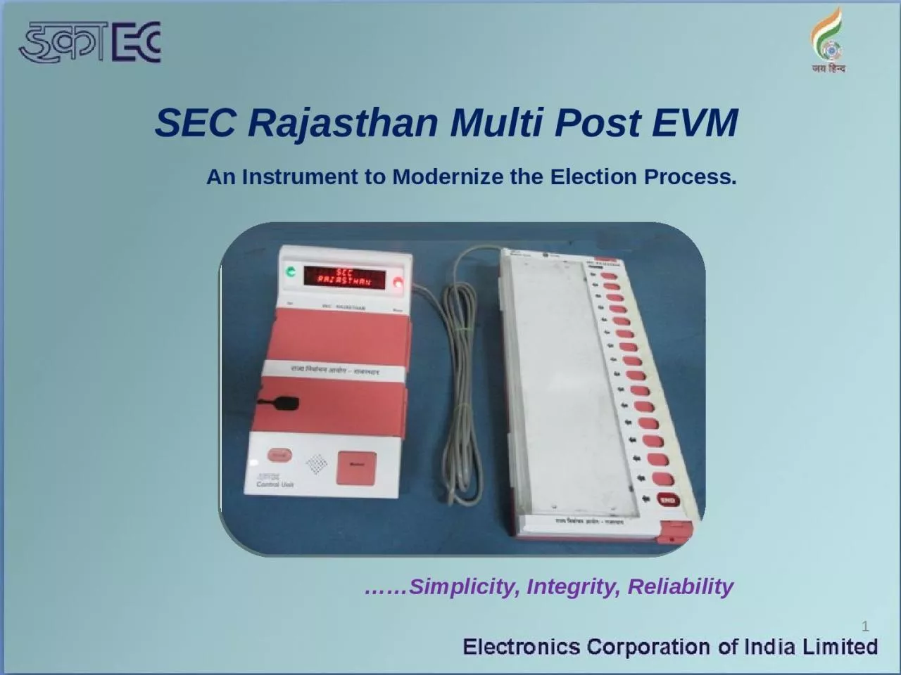
1 Simplicity Integrity Reliability An Instrument to Modernize the Election Process 2 Electronic Voting Machine also known as EVM is electronic device for casting and counting of votes ID: 928506
Download Presentation The PPT/PDF document "SEC Rajasthan Multi Post EVM" is the property of its rightful owner. Permission is granted to download and print the materials on this web site for personal, non-commercial use only, and to display it on your personal computer provided you do not modify the materials and that you retain all copyright notices contained in the materials. By downloading content from our website, you accept the terms of this agreement.
Slide1
SEC Rajasthan Multi Post EVM
1
……Simplicity, Integrity, Reliability
An Instrument to Modernize the Election Process.
Slide22
Electronic Voting Machine (also known as EVM) is electronic device for casting and counting of votes.
An EVM is designed with two units: the control unit and the balloting unit. These units are joined together by a 5mtr cable.
The control unit of the EVM is kept with the presiding officer or the polling officer. The ballot unit is kept within the voting compartment for voters to cast their votes.
SEC EVM INTRODUCTION
Slide3With the EVM, the polling officer will press the Ballot Button which enables the voter to cast their vote.
A list of candidates names and/or symbols will be available on Ballot Unit with a Pink button next to it.
The voter can press the button next to the candidate’s name they wish to vote for.
3
SEC EVM INTRODUCTION
Slide44
The EVM is designed to store voting data and display/print result.
It operates on battery and is simple to operate and can be installed in a short period.
There is no scope for invalid votes and total secrecy of the voting data is maintained.
The EVM facilitates quick and accurate counting.
SEC EVM INTRODUCTION
Slide5Capacity to record 2000 voters/ 8000 votes in CU
Real Time Clock to display current Date and Time.
24 character 17 segment Alphanumeric display on the Control Unit (CU) for displaying messages
Display of battery pack power status
Encrypted voting data is securely stored in SDMM with redundancy.
END of vote facility for partial voting/under voting.
Facility to record Unfinished Voters.
5
SEC EVM Features
Slide6Secured
Detachable Memory Module (SDMM) for immediate reusability of CU.
Built in Anti-Tamper circuit in CU and
BU
Provision for sealing of different compartments
.
Time stamping of events and each voter’s franchise
.
Facility to print Result data and time stamp data.
6
SEC EVM Features
Slide77
A Ballot Unit (BU) caters to a maximum of 15 candidates. 16th Candidate Button (i.e. END button) is used as END OF VOTE. In case of multiple BUs, END button of the last BU is used as END of VOTE.
Maximum number of BUs that can be cascaded to one control unit is Four, thereby catering to a maximum of 60 contesting candidates.
Braille markers for candidate number identification on BU for visually challenged.
SEC EVM Features
Slide8Unique electronic serial number is loaded in the factory for CU, BU and SDMM and the same number is laser marked on the cabinets.
The Real time clock can be set only in clear state, i.e., before the machine is enabled for the first ballot.
8
SEC EVM Features
Slide99
SDMM has unique serial number (electronic as well as laser marked on the module).
On the day of poll SDMM is locked (s/w locking)to the CU for voting from first ballot operation.
In between polling operation system does not permit SDMM to continue voting operation in any other units.
SEC EVM Features
Slide1010
However in any other control unit, CLOSE, RESULT and CLEAR operations can be performed with the SDMM.
Voting data along with event log is stored in SDMM
EVM (CU and BU) with new SDMM can be deployed for next election for immediate reusability.
SEC EVM Features
Slide11MODEL LAYOUT OF POLLING STATION/BOOTH
11
Slide12CLOSE
CLEAR
RESULT
SEQUENCE OF
OPERATIONS IN EVM
12
CAND. SET
BALLOT
Slide13CARRYING CASES
The control unit and ballot unit are packed separately in special carrying cases for transportation &
storage.
Latches are to be carefully operated to open the carrying cases.
For BALLOT UNIT
For CONTROL UNIT
13
LATCH
Slide14CU is the master unit
Polling officer operates the CU
Permits voter to cast his vote in the Ballot Unit
Records securely the votes polled in the BUdisplays the following on demand
Election result
EVM status & error messages
14
FUNCTIONS OF
CONTROL UNIT(CU)
Slide15CONTROL UNIT
DISPLAY SECTIONCANDIDATE SET
SECTIONRESULT SECTION
BALLOT SECTION
15
BATTERY PACK
SECTION
Slide161. ‘ON’ lamp
2. ‘BUSY’ lamp
3. 17 Segment Display
16
1
2
CONTROL UNIT – DISPLAY SECTION
3
Slide171. CANDIDATE SET compartment door
2. SDMM 3. CANDIDATE SET button
4. Provision for sealing
17
2
CONTROL UNIT – CANDIDATE SET SECTION
3
4
1
Slide181. BATTERY PACK compartment door
2. BATTERY 3. Provision for sealing
18
2
CONTROL UNIT – BATTERY PACK SECTION
1
3
Slide191. CLOSE compartment door
2. Provision for seal 3. closed cap for ‘CLOSE’ button
19
2
1
CONTROL UNIT – CLOSE SECTION
3
Provision for seal
‘
CLOSE’ button
Elliptical opening for ‘RESULT1’ & ‘RESULT2’ keyRESULT compartment door
Inner compartment door
20
1
4
CONTROL UNIT – RESULT SECTION CONTINUED
…
2
3
5
1. ‘CLOSE’ Button
2. ‘RESULT1’ Button 3. ‘RESULT2’ Button4. ‘CLEAR’ Button
5. Frame for green paper seal
21
1
4
CONTROL UNIT – RESULT SECTION CONTINUED…
2
5
3
1. ‘TOTAL’ Button
2. ‘BALLOT’ Button
3. BUZZER
22
1
3
CONTROL UNIT – BALLOT SECTION
2
1. Power ON /OFF switch
2. 9 pin female connector for BU interface
3. Rear cover 4. 9 pin male connector for Data interface
23
2
4
CONTROL UNIT (Operator View
)
3
1
Slide24SWITCHES/BUTTONS OF CU
--- for conducting election 1.ON/OFF - to turn on & off the CU
2.CAND.SET -to set the no of contestants 3.BALLOT - to permit the voter to cast
vote (CU enables BU to accept vote)
4. TOTAL - display the total votes
polled till then , battery status,
date & time , no of contestants
5. CLOSE - to end the polling
(no further voting is allowed)
24
Slide25SWITCHES/BUTTONS OF CU…6.
RESULT 1 - display in sequence the election result7. RESULT2 - display in sequence the election result8. CLEAR - erase the recorded voting data
Two LED indicators to the operator
a) ON lamp -
Green
LED, implying EVM is powered up b) BUSY lamp - red LED
ON - when ballot button is pressed on CU
OFF - turns off after the vote is recorded in CU
Alphanumeric display for messages & EVM status
25
Slide26CU enables BU to accept vote by the voter
Voter casts his vote by press of a button on the ballot unit
One ballot unit supports 15 candidates
Maximum of 4 bus can be connected(60 contestants)Powered from control unit
26
FUNCTIONS OF BALLOT UNIT
Slide271. ‘READY’ LAMP 2. TOP RELEASE LATCH
3. SLIDE SWITCH4. CANDIDATE LAMPCANDIDATE BUTTON
BALLOT PAPER SCREEN FOR CANDIDATE NAMES AND SYMBOLS
27
1
2
BALLOT UNIT (Operator View)
5
4
3
6
Slide281. Release latches for ballot paper screen
2. Provision for thread seal
3. Ballot paper screen
28
BALLOT UNIT – BALLOT PAPER SCREEN
3
2
1
Slide291. Masking tab
2. Ready led
3. Candidate button 4. Provision for thread seal 5. Inner view of ballot paper seal
29
BALLOT UNIT – INNER VIEW
4
2
1
3
5
Slide3030
INSTALLATION OF POWER PACK:
Slide3131
INTERCONNECTION OF CU WITH BUs
BU Slide Switch Positions
(Hood)
Red Latch
Black Latch
(BU Interconnecting Door)
BU Cable
Slide3232
OPERATION
AND
DISPLAY MESSAGES ON CU
Note:
SDMM should be connected before switching on the CU otherwise SDMM NOT RESPONDING message will be displayed on CU and CU will not ACCEPT any further command.
Slide33CU POWER ON DISPLAY MESSAGES
33
SEC
RAJASTHAN
Ready
lamps on all c
onnected BUs blink once, if BUs are connected.
WARD
123A
BOOTH
1285
DTE
15-03-18
TME
10-38-56
Indicates date
in
DD-MM-YY and
time
is in HH-MM-SS format.
RJSCU011111
RJSDM014566
Indicates the serial number of Control Unit and SDMM.
POST
1
Indicates the status of the battery (HIGH/MEDIUM/LOW)
CANDS
5
SEATS
1
BATTERY
MEDIUM
Indicates the number of contesting candidates and seats.
Indicates the number of posts
Indicates the Post number
Indicates the Ward number & Booth number
NUMBER OF
POSTS 1
(Operation :Switch ON CU)
Slide34DISPLAY MESSAGES ON CU WHILE DOING CANDIDATE SET
34
ENTER WARD
NO -
Blinking message Indicates to enter required ward number
ENTER
BOOTH
NO -
Note: To enter Ward number and booth number BU01 keys acts as follows
BU01
keys
1 to 9 for digits 1 to 9.
BU01 10th key for digit 0
BU01 key 11 for - ‘dash’
BU01 key 12 for Alphabets
BU01 15th key for RESET/CLEAR
BU01 16th key for ENTER
BU01
key
13
to confirm/Save the Alphabet only
BU01 key
14
is
Reserved
Ward number and Booth number accepts maximum 4 digits (Alphanumeric)
Blinking message Indicates to enter required Booth number
(Operation: Connect BU
Switch ON CU
Press
Cand
. Set Button)
Slide3535
NUMBER
OF POSTS -
POST 2
1ST CAND --
POST 1
1ST CAND --
POST 1
LAST CAND --
CU displays all the entered values in sequence starting from ward No. Please ensure correctness.
Note
: BU keys acts as follows
16
th
key of each BU is
reserved.
16
th
key of last BU acts as END
button.
(Operation: Press Ballot button in CU & caste votes in BU)
Indicates to enter Required number of posts
Ex: 2
Indicates to enter 1
st
candidate of
post 1
(
select
first
candidate
as per ballot paper)
POST 2
LAST CAND --
Indicates to enter last candidate of
post 1
(press corresponding key in ballot unit)
Indicates to enter first candidate of
post 2
(press corresponding key in ballot unit)
Indicates to enter last candidate of
post 2
(press corresponding key in ballot unit)
DISPLAY MESSAGES ON CU WHILE DOING CANDIDATE SET
Slide3636
BATTERY
HIGH
TOTAL
VOTERS
0
DTE 15-03-19
TME 10-38-56
NUMBER
OF POSTS --
Indicates the status of the battery (HIGH/MEDIUM/LOW)
Indicates the number of posts
Indicates
total
number of voters
Indicates date
in
DD-MM-YY
and
time in
HH-MM-SS format.
DISPLAY MESSAGES ON
CU
AFTER TOTAL BUTTON PRESSED
(Operation :Press Total Button on CU)
Slide3737
CLOSING
NUMBER
OF
POSTS 2
DTE 15-03-19
TME 10-38-56
RJSCU011111
RJSDM014566
Indicates Number of posts
Indicates date
in
DD-MM-YY and
time in
HH-MM-SS
format
. (Closing Date & Time)
TOTAL VOTERS
4
POLL CLOSED
Indicates Total number of voters
Indicates that poll is closed
Indicates the serial number of Control Unit and SDMM.
DISPLAY MESSAGES ON CU
AFTER
CLOSE BUTTON PRESSED
Indicates
the Closing operation started.
Slide3838
COMPUTING
RESULT
PST HH-MM-SS
PET HH-MM-SS
RJSCU000001
RJSDM000003
Indicates date of Polling
POLL RESULT
PDT DD-MM-YY
Indicates the serial number of Control Unit and SDMM.
TOTAL VOTERS
4
Indicates Total votes casted for post1 excluding under votes
POST1
POLLED
VOTES 2
Indicates the number of posts
Indicates total number of voters including unfinished voters
PST- Poll Start Time
PET- Poll End Time
NUMBER OF
POSTS 2
DISPLAY MESSAGES ON CU AFTER RESULT BUTTON PRESSED
Slide3939
UNDER
VOTES - 2
CANDIDATE-1
VOTES
-
CANDIDATE-2
VOTES-
END
Indicates number of unfinished voters
Indicates number of under votes for post1
UNFINISHED
VOTERS-
Displays number of votes polled for candidate 1 of post1
Displays number of votes polled for candidate 2 of post1
After displaying results of all posts following messages will be displayed at the end.
DISPLAY MESSAGES ON CU AFTER RESULT BUTTON PRESSED
POLL
DAY CU
xxxxxxxxx
It displays CU SLNO in which votes were polled
CANDS 2
SEATS - 1
Indicates the number of contesting candidates and seats.
Slide4040
DELETING
POLLED VOTES
POLLED
VOTES 0
POST 1
CANDS 2
SEATS 1
CANDIDATE-1
VOTES-0
Indicates the number of contesting candidates and seats of post1
Indicates the Post number
UNDER
VOTES
0
Indicates polled votes as zero
Indicates under votes as zero
Indicates zero votes for candidate 1
Note:
CU displays zero votes
against
each candidate in all posts after clear
operation. Finally Unfinished Voters shown as Zero & End Message displayed
Indicates deleting polled votes with long buzzer sound
DISPLAY MESSAGES ON CU AFTER CLEAR BUTTON PRESSED
TOTAL
VOTERS
0
Indicates Total number of
voters as zero
Slide4141
Under votes & Unfinished Voters
Under votes: If voter chooses to press END button without voting for required number of seats then the unselected seats are treated as under votes by the machine.
Unfinished Voters:If a Voter casts one or more votes and does not to press END button without voting for required number of seats and leaves the polling booth then to record the votes cast the CU needs to be restarted for further operation. That voter is counted as an unfinished voter and the numbers of unselected seats are treated as under votes by the CU.
Slide4242
INVALID
OPERATION
INOPERATIVE
PRESSED ERROR
ERROR
CLOCK ERROR
Indicates CU is not fit for use.
Indicates
any button/s in any ballot unit is already pressed or jammed.
SDMM NOT
RESPONDING
Indicates
CU is not fit for use.
Indicates
SDMM not present/responding
Indicates the CU button pressed is not in sequence of operation
ERROR
MESSAGES ON
CU
LINK ERROR -1
Indicates
interconnecting cable has not been properly fixed OR slide switch is in wrong position.
Indicates
Clock is not set/working.
Note: Ready LED blinking Indicates BU is not fit for use.
SDMM
CHANGED
Indicates
SDMM is not in clear state.
Slide43Election Process
Slide4444
1) First Level Checking (FLC)
ECIL Engineers reports with jigs, tools, spares & Consumables etc.
First level Checking is done to ensure the fitness of the EVMs for Election usage.Removal of old tags & cleaning of units is done FLC-OK Green Stickers is affixed on CU and BU on all FLC OK units.
Pink paper seal in all FLC-OK CUs
Mock-poll will be done as per guidelines.
Rejected Red Sticker is affixed on faulty units
Slide4545
2) Commissioning
ECIL Engineers reports to concerned authorities to assist in following commissioning process.
Ballot Unit (BU): Inserting the ballot paper and masking the unused buttons.
Control Unit (CU):
Installation of the new power pack.
Setting the no of Contesting Candidates connecting CU and BU polling station wise.
Sealing of the Units-
Candidate set section of CU
BU Unit & Pink Seal in BU Unit.
Conduct mock-poll on EVM as per guide lines.
Slide4646
3) Distribution
Movement of Units to Polling Station
ECIL Engineers are deputed to distribution centers to extend technical support.
Polling parties ensures the matching of serial numbers , Seals & Address tags on CU and BU units as well as on their carrying cases.
Slide4747
4) Polling
ECIL Engineers extends technical support during polling.
Mock poll is conducted as per guide lines.
CRC done to clear CU and necessary compartments are sealed.
Actual Poll is started after completion of the Voter identification process.
If unit is failed, the corresponding unit/sets may be replaced as per guidelines.
After poll is closed, Units are kept in their carrying cases and brought to collection center.
Slide4848
5) Counting
ECIL Engineers are deputed to counting centers to extend technical support.
Counting is Done as per the guideline.
Results are extracted from CUs and tabulated.
Winning candidate is declared by concerned authority
--------------****************----------------
Slide4949
THANK YOUwww.ecil.co.in