/
Structural Assessments of Magnets for the Next Generation Structural Assessments of Magnets for the Next Generation

Structural Assessments of Magnets for the Next Generation - PDF document

cady
cady . @cady
Follow
343 views
Uploaded On 2021-08-09

Structural Assessments of Magnets for the Next Generation - PPT Presentation

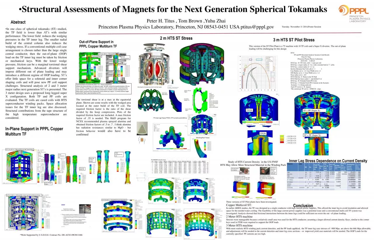
Spherical TokamaksPeter H Titus Tom Brown YuhuZhaiPrinceton Plasma Physics Laboratory Princeton NJ 085430451 USA ptitusppplgovAbstractConclusionInPlane Support in PPPL Copper MultiturnTF3 m HTS ST ID: 860387

current hts friction st32 hts current st32 friction leg coils case coil radius plane set field support structural oop

Share:

Link:

Embed:

Download Presentation from below link

Download Pdf The PPT/PDF document "Structural Assessments of Magnets for th..." is the property of its rightful owner. Permission is granted to download and print the materials on this web site for personal, non-commercial use only, and to display it on your personal computer provided you do not modify the materials and that you retain all copyright notices contained in the materials. By downloading content from our website, you accept the terms of this agreement.


Presentation Transcript

1 • Structural Assessments of Magnets fo
• Structural Assessments of Magnets for the Next Generation Spherical Tokamaks Peter H. Titus , Tom Brown , Yuhu Zhai Princeton Plasma Physics Laboratory, Princeton, NJ 08543 - 0451 USA ptitus@pppl.gov Abstract Conclusion In - Plane Support in PPPL Copper Multiturn TF 3 m HTS ST Pilot Stress 2 m HTS ST Stress Tuesday November 11 2014,Poster Session • In one class of spherical tokamaks (ST ) studied, the TF field is lower than AT’s with similar performance . The lower field reduces the wedging pressures in the TF inner leg . The smaller radial build of the central column also reduces the wedging stress . If a conventional multiple coil case arrangement is chosen rather than the large single central conductor , then the out - of - plane (OOP) load on the TF inner leg must be taken by friction or mechanical keys . With the lower wedge pressure, friction can be a marginal torsional shear support mechanism . Advanced divertors will impose different out of plane loading and may introduce a different regime of OOP loading . ST’s offer little space for a solenoid and inner corner shaping coils and will pose new PF coil support challenges . Structural analysis of 2 and 3 meter major radius next generation ST’s is presented . The 3 meter design uses a proposed long legged super X configuration . Both TF and PF coils are evaluated . The TF coils are cased coils with HTS superconductor winding packs . Space allocation issues for the TF inner leg are also discussed . Structural contributions from the tape structure of the high temperature superconductor are considered . Inner Leg Stress Dependence on Current Density Three versions of ST Pilot plants have been investigated. Copper Multicoil ST: In earlier ARIES studies, the TF was designed as a single conductor with high current power supplies. This allwed the inner leg to avoid insulation and allowed space for the needed water cooling. The feasibility of the large current power supplies was a potential issue and a conventio nal multi coil TF system was investigated. Analysis showed that frictional interactions between the inner legs could be sufficient too resist the out – of - pla ne loading. 2 Meter HTS machine Stresses were manageable because a relatively small area was used for the HTS conductor, assuming a larger allowed current de nsi ty. Keys, similar to the corner keys used in ITER were required to support the OOP loads 3 Meter HTS machine With more realistic HTS winding pack current densities, and the PF loads applkied , the TF inner leg case stresses of ~900 Mpa are above the 666 Mpa allowable, and adjustments will be needed to the current densities and inner leg cross sections – or improved yield case materials will be needed. The OOP Loads for the currently specified PF currents are too high. Out - of - Plane Support in PPPL Copper Multiturn TF The torsional shear is at a max at the equatorial plane . Shown are some results with the wedged area located at the outer build of the TF coil . The required friction factor is the ratio of the shear divided by the hoop compression . Plots of the required friction factor are included . A max friction factor of . 35 is needed . The R&D program for NCSX recommended plasma sprayed alumina and obtained friction factors of . 5 to . 7 . I think alumina has radiation resistances similar to MgO - but friction behavior would also have to be confirmed *Work Supported by U.S.D.O.E. Contract No. DE - AC02 - 09CH11466 ST32 TF and PF Structural Analysis Systems Code Results Peter H. Titus Princeton Plasma Physics Laboratory 20151103 11:00:45 ST32 has 10 TF Coils, with 1 turns per coil ST32 has a major radius of 3 m with a toroidal field of 7 at Ro ST32 has a minor radius of 1.2 m Section filename=hse7 divx,divy = 1 1 Case Radius set to 1.4 Case Width set to .6 OIS Radius set to 2 Case Width set to 1.2 Nose radius set to .423 ST32 Path has 8 Points in the TF Path ST32 Path has been scaled 1 and shifted 0 m ST32 has 20 Poloidal Field (PF) Coils ST32 has 2 Poloidal Field (PF) Currents in the Scenario Scenario 2 is being analyzed Each TF sector is 36 degrees The current per TF coil is: 10500334. amps This version of the ST Pilot Plant is a 7T machine with 10 TF coils and a Super X divertor .. The out - of - plane loading will be challenging for this design TFON TF + PF (Super X) TFON TF + PF (Super X) Study of HTS Current Density in the US - FNSF HTS May Allow More Structural Material in the Winding Pack