PDF-Building for Everyone:A Universal Design Approach
Author : conchita-marotz | Published Date : 2016-12-08
Facilities in buildings II Centre for Excellence in Universal DesignCreating an environment that can be used by all people regardless of their age size disability
Presentation Embed Code
Download Presentation
Download Presentation The PPT/PDF document "Building for Everyone:A Universal Design..." is the property of its rightful owner. Permission is granted to download and print the materials on this website for personal, non-commercial use only, and to display it on your personal computer provided you do not modify the materials and that you retain all copyright notices contained in the materials. By downloading content from our website, you accept the terms of this agreement.
Building for Everyone:A Universal Design Approach: Transcript
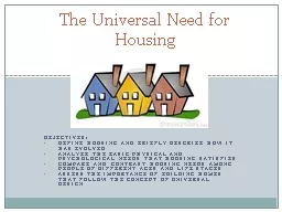
Facilities in buildings II Centre for Excellence in Universal DesignCreating an environment that can be used by all people regardless of their age size disability or abilityThe National Disabili. Gibson Design Group approaches commercial design differently than most firms. When we design for commercial clients, we view the design as marketing as much as it is interior design. The filter building block together with an external clock and a few resistors can produce various second order functions The filter building block has 3 output pins One of the output pins can be configured to perform highpass all pass or notch funct I Planning and policy II Centre for Excellence in Universal DesignCreating an environment that can be used by all people, regardless of their age, size, disability or ability. The National Disabilit Presented By . adina. . mulliken. , may 2014. Today’s Intended Outcomes. Explore concepts of Universal Design.. Name two sets of web accessibility technical guidelines (WCAG 2.0 & Section 508).. UD Principle:. Perceptible Information. Week. 4. Use of Different Modes (Pictorial, Sound etc). Use of Different Modes (Pictorial, Sound etc). Use of Different Modes (Pictorial, Sound etc). Maximize Legibility of Information. &. Assistive Technology. Creating Accessible Classrooms. Karen Coffey. What is Universal Design for Learning?. . . Universal Design for Learning, or UDL, is an instructional approach that opens opportunities for all students by using digital media and flexible instruction to help students meet their educational goals. . How to develop an accessible online course. Introduction to Universal Design (UD). It is a framework for designing curricula and making learning environments conducive for a large population. . It minimizes the need for special accommodations while giving full access to content. . Principles . into Astronomy Education and . Research. Panelists:. Alicia . Aarnio. . (University of Colorado/AAS WGAD). Jackie . Monkiewicz. . (Arizona State/AAS . WGAD). Sharron Rush (. Knowbility.org. GTA . Orientation, August 14, 2014. Allison Kidd & Shannon . Lavey. A. ssistive . T. echnology . R. esource . C. enter. . (ATRC). Marla Roll Director. Shannon Lavey. Service Coordinator and Provider. Analyze the basic physical and psychological needs that housing satisfies. Compare and contrast housing needs among people of different ages and life stages. Assess the importance of building homes that follow the concept of universal design. Stijn Claessens . based on:. Geneva Report on the World Economy 12. . Stijn Claessens (IMF), Richard J. Herring (Wharton School. ),. . Dirk Schoenmaker (Duisenberg school of finance). Conference: “. Presented by. Stacey M. Davis. PD Coordinator for Teaching Excellence. February 6, 2018. Agenda. Communication. Universal Design - General. Universal Design for Learning. Applying the 7 Principles in Class. . Amy Kathleen Brown. SES 662. Who?. The teachers of my (pretend) elementary school where I am the (pretend) school librarian.. What?. This three-hour long workshop will be offered as part of a teacher in-service. . Employee Fellow for Technology Proficiency. 2020-2021. Joanna DeYoung. Good Design is Accessible. Universal Design . is Accessible Design. Accessible Documents and Universal Design. Fellowship Aspects.
Download Rules Of Document
"Building for Everyone:A Universal Design Approach"The content belongs to its owner. You may download and print it for personal use, without modification, and keep all copyright notices. By downloading, you agree to these terms.
Related Documents