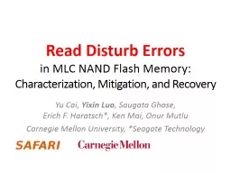
Characterization Mitigation and Recovery Yu Cai Yixin Luo Saugata Ghose Erich F Haratsch Ken Mai Onur Mutlu Carnegie Mellon University Seagate Technology Executive Summary ID: 759533
Download Presentation The PPT/PDF document "Read Disturb Errors in MLC NAND Flash M..." is the property of its rightful owner. Permission is granted to download and print the materials on this web site for personal, non-commercial use only, and to display it on your personal computer provided you do not modify the materials and that you retain all copyright notices contained in the materials. By downloading content from our website, you accept the terms of this agreement.
Slide1
Read Disturb Errors in MLC NAND Flash Memory:Characterization, Mitigation, and Recovery
Yu Cai, Yixin Luo, Saugata Ghose, Erich F. Haratsch*, Ken Mai, Onur MutluCarnegie Mellon University, *Seagate Technology
Slide2Executive Summary
Read disturb errors limit flash memory lifetime todayApply a high pass-through voltage (Vpass) to multiple pages on a readWe characterize read disturb on real NAND flash chipsSlightly lowering Vpass greatly reduces read disturb errorsSome flash cells are more prone to read disturbTechnique 1: Mitigate read disturb errors onlineVpass Tuning dynamically finds and applies a lowered VpassFlash memory lifetime improves by 21%Technique 2: Recover after failure to prevent data lossRead Disturb Oriented Error Recovery (RDR) selectively corrects cells more susceptible to read disturb errorsReduces raw bit error rate (RBER) by up to 36%
2
Slide3Outline
Background (Problem and Goal)Key Experimental ObservationsMitigation: Vpass TuningRecovery: Read Disturb Oriented Error RecoveryConclusion
3
Slide4Outline
Background (Problem and Goal)Key Experimental ObservationsMitigation: Vpass TuningRecovery: Read Disturb Oriented Error RecoveryConclusion
4
Slide5NAND Flash Memory Background
Flash Memory
Page 1
Page 0
Page 2
Page 255
……
Page 257
Page 256
Page 258
Page 511
……
……
Page M+1
Page M
Page M+2
Page M+255
……
Flash Controller
5
Block 0
Block 1
Block N
Read
Pass
Pass
…
Pass
Slide6Sense Amplifiers
Flash Cell Array
Block X
Page Y
Sense Amplifiers
6
Row
Column
Slide7Flash Cell
Floating Gate
Gate
Drain
Source
Floating Gate Transistor
(
Flash Cell)
V
th
= 2.5 V
7
Slide8Flash Read
V
read
= 2.5 V
V
th
= 3
V
V
th
=
2
V
1
0
V
read
= 2.5 V
8
Gate
Slide9Flash Pass-Through
V
pass
= 5 V
V
th
=
2
V
1
V
pass
= 5 V
9
Gate
1
V
th
= 3
V
Slide10Read from Flash Cell Array
3.0V
3.8V
3.9V
4.8V
3.5V
2.9V
2.4V
2.1V
2.2V
4.3V
4.6V
1.8V
3.5V
2.3V
1.9V
4.3V
V
read
= 2.5 V
V
pass
= 5.0 V
V
pass
= 5.0 V
V
pass
= 5.0 V
1
1
0
0
Correct values for page 2:
10
Page 1
Page 2
Page
3
Page
4
Pass (5V)
Read (2.5V)
Pass (5V)
Pass (5V)
Slide11Read Disturb Problem: “Weak Programming” Effect
3.0V
3.8V
3.9V
4.8V
3.5V
2.9V
2.4V
2.1V
2.2V
4.3V
4.6V
1.8V
3.5V
2.3V
1.9V
4.3V
Repeatedly read page 3 (or any page other than page 2)
11
Read (2.5V)
Pass (5V)
Pass (5V)
Pass (5V)
Page 1
Page 2
Page
3
Page
4
Slide12V
read
= 2.5 V
V
pass
= 5.0 V
V
pass
= 5.0 V
V
pass
= 5.0 V
0
1
0
0
Read Disturb Problem: “Weak Programming” Effect
High pass-through voltage induces “weak-programming” effect
3.0V
3.8V
3.9V
4.8V
3.5V
2.9V
2.1V
2.2V
4.3V
4.6V
1.8V
3.5V
2.3V
1.9V
4.3V
Incorrect values from page 2:
12
2.4V
2.6V
Page 1
Page 2
Page
3
Page
4
Slide13Goal: Mitigate and Recover Read Disturb Errors
Read disturb errors: Reading from one page can alter the values stored in other unread pages
13
Slide14Outline
Background (Problem and Goal)Key Experimental ObservationsMitigation: Vpass TuningRecovery: Read Disturb Oriented Error RecoveryConclusion
14
Slide15Methodology
FPGA-based flash memory testing platform [Cai+, FCCM ‘11]Real 20- to 24-nm MLC NAND flash chips0 to 1M read disturbs0 to 15K Program/Erase Cycles (PEC)
15
Slide16Read Disturb Effect on Vth Distribution
Normalized Threshold Voltage
× 10
-3
6
5
4
3
2
1
0
0
50
100
150
200
250
300
350
400
450
500
PDF
0 (No
Read Disturbs)
0.25M Read Disturbs
0.5M Read Disturbs
1M Read Disturbs
ER state
P1 state
P2 state
P3 state
V
th
gradually increases with read disturb counts
16
Slide17Other Experimental Observations
Lower threshold voltage states are affected more by read disturbWear-out increases read disturb effect
17
Slide18Reducing The Pass-Through Voltage
18
Key Observation 1:
Slightly lowering
V
pass
greatly reduces read
disturb errors
Slide19Outline
Background (Problem and Goal)Key Experimental ObservationsMitigation: Vpass TuningRecovery: Read Disturb Oriented Error RecoveryConclusion
19
Slide20Read Disturb Mitigation: Vpass Tuning
Key Idea: Dynamically find and apply a lowered VpassTrade-off for lowering VpassAllows more read disturbsInduces more read errors
20
Slide21Read Errors Induced by Vpass Reduction
21
3.0V
3.8V
3.9V
4.8V
3.5V
2.9V
2.4V
2.1V
2.2V
4.3V
4.6V
1.8V
3.5V
2.3V
1.9V
4.3V
V
read
= 2.5 V
V
pass
= 4.9 V
V
pass
= 4.9 V
V
pass
= 4.9 V
1
1
0
0
Reducing
V
pass
to 4.9V
Page 1
Page 2
Page
3
Page
4
Slide22Read Errors Induced by Vpass Reduction
22
3.0V
3.8V
3.9V
4.8V
3.5V
2.9V
2.4V
2.1V
2.2V
4.3V
4.6V
1.8V
3.5V
2.3V
1.9V
4.3V
V
read
= 2.5 V
V
pass
= 4.7 V
V
pass
= 4.7 V
V
pass
= 4.7 V
1
0
0
0
Reducing
V
pass
to 4.7V
Incorrect values from page 2:
Page 1
Page 2
Page
3
Page
4
Slide23Utilizing the Unused ECC Capability
23
01 02 03 04 05 06 07 08 09 10 11 12 13 14 15 16 17 18 19 20
21
N
-day Retention
1.0
0.8
0.6
0.4
0.2
0
RBER
× 10-3
ECC Correction Capability
Unused ECC capability
Huge unused ECC correction capability can be used to tolerate read errors
2. Unused
ECC capability
decreases over time
Dynamically adjust
V
pass
so that read errors fully utilize the unused ECC capability
Slide24Vpass Reduction Trade-Off Summary
Conservatively set Vpass to a high voltageAccumulates more read disturb errors at the end of each refresh intervalNo read errorsDynamically adjust Vpass to unused ECC capabilityMinimize read disturb errorsControl read errors to be tolerable by ECCIf read errors exceed ECC capability, read again with a higher Vpass to correct read errors
24
Slide25Vpass Tuning Steps
Perform once for each block every day:Estimate unused ECC capabilityAggressively reduce Vpass until read errors exceeds ECC capabilityGradually increase Vpass until read error just becomes less than ECC capability
25
Slide26Evaluation of Vpass Tuning
19 real workload I/O tracesAssume 7-day refresh periodSimilar methodology as before to determine acceptable Vpass reductionOverhead for a 512 GB flash drive:128 KB storage overhead for per-block Vpass setting and worst-case page24.34 sec/day average Vpass Tuning overhead
26
Slide27Vpass Tuning Lifetime Improvements
27
V
pass
Tuning
Average lifetime improvement: 21.0%
Slide28Outline
Background (Problem and Goal)Key Experimental ObservationsMitigation: Vpass TuningRecovery: Read Disturb Oriented Error RecoveryConclusion
28
Slide29Read Disturb Resistance
29
R
P
Disturb-Resistant
Disturb-Prone
Normalized V
th
PDF
N read disturbs
N read disturbs
R
P
Slide30Observation 2: Some Flash Cells AreMore Prone to Read Disturb
30
P1
ER
Normalized V
th
PDF
P
P
P
P
R
P
R
P
R
P
R
P
Disturb-prone cells have higher threshold voltages
Disturb-resistant cells have lower threshold voltages
After 250K read disturb:
Disturb-prone
ER state
Disturb-resistant
P1 state
Slide31Read Disturb Oriented Error Recovery (RDR)
Triggered by an uncorrectable flash errorBack up all valid data in the faulty blockDisturb the faulty page 100K times (more)Compare Vth’s before and after read disturbSelect cells susceptible to flash errors (Vref−σ<Vth<Vref−σ)Predict among these susceptible cellsCells with more Vth shifts are disturb-prone Higher Vth stateCells with less Vth shifts are disturb-resistant Lower Vth state
31
Slide32RDR Evaluation
32
×
10
-3
12
10
8
6
4
2
0
RBER
Read Disturb Count
0
0.2M
0.4M
0.6M
0.8M
1
M
No Recovery
RDR
Reduce total error counts up to 36% @ 1M read disturbs
ECC can be used to correct the remaining errors
Slide33Outline
Background (Problem and Goal)Key Experimental ObservationsMitigation: Vpass TuningRecovery: Read Disturb Oriented Error RecoveryConclusion
33
Slide34Executive Summary
Read disturb errors limit flash memory lifetime todayApply a high pass-through voltage (Vpass) to multiple pages on a readWe characterize read disturb on real NAND flash chipsSlightly lowering Vpass greatly reduces read disturb errorsSome flash cells are more prone to read disturbTechnique 1: Mitigate read disturb errors onlineVpass Tuning dynamically finds and applies a lowered VpassFlash memory lifetime improves by 21%Technique 2: Recover after failure to prevent data lossRead Disturb Oriented Error Recovery (RDR) selectively corrects cells more susceptible to read disturb errorsReduces raw bit error rate (RBER) by up to 36%
34
Slide35Read Disturb Errors in MLC NAND Flash Memory:Characterization, Mitigation, and Recovery
Yu Cai, Yixin Luo, Saugata Ghose, Erich F. Haratsch*, Ken Mai, Onur MutluCarnegie Mellon University, *Seagate Technology
Slide36Read Disturb Induced RBER Increases Faster with Higher PEC
× 10
-3
4.0
3.5
3.0
2.5
2.0
1.5
1.0
0.5
0
Raw Bit Error Rate (RBER)
0
20K
40K
60K
80K
100K
Read Disturb Count
PEC
Slope
15K1.90×10-810K9.10×10-98K7.50×10-95K3.74×10-94K2.37×10-93K1.63×10-92K1.00×10-9
Faster
Slower
36
Slide37Threshold Voltage Increases with Read Disturb Count
Showing results for P1 state @ 8K PEC, other states have similar trends
37
Slide38Lower Voltage States AreMore Prone to Read Disturb
38
ER State
P1 State
Slide39Reducing Vpass Increases Tolerable Read Disturb Count
× 10
-3
RBER
1.6
1.4
1.2
1.0
0.8
0.6
10
4
10
5
10
8
10
9
Read Disturb Count
10
6
10
7
94%
V
pass
95%
V
pass
96%
V
pass
97%
Vpass
98% Vpass
99% Vpass
100% Vpass
0.4
94%
95%
96%
97%
98%
99%
100%
Pct. Vpass Value100%99%98%97%96%95%94%Rd. Disturb. Cnt.1x1.7x6.8x22x100x470x1300x
39
Slide40Pass-Through Voltage Reduction Induced Read Error
40
× 10
-3
Addl. RBER Due to Reduced
Vpass
Relaxed Vpass
0.75
0.5
0.25
480
485
490
495
500
505
510
1
.0
0-day
1-day
2-day
6-day
9-day
17-day
21-day
0
Slide41Read Errors Induced by Vpass Reduction
Will generate a read error only if:Max(Vth) > VpassCorrect read value is 1These errors do not affect lifetimecan usually be tolerated by the unused ECC capabilityThese errors are temporarycan be corrected (if necessary) by reading with the default Vpass
41
Slide42Illustration of Vpass Tuning Results
42
Slide43Some Flash Cells AreMore Prone to Read Disturb
43
Predict to be ER state
Area III is correct
Area IV is 50/50
Predict to be P1 stateArea I is correctArea II is 50/50
Showing ∆V
th
with 8K
PEC
from 250K to 350K read disturbs