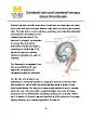
Ruptured Brain aneurysms occur in over 30000 people within the US alone primarily affecting women causing onset nausea vomiting stiff neck loss of consciousness and even death Aneurysm Clip Classification Scheme ID: 617752
Download Presentation The PPT/PDF document "A cerebral aneurysm is a weak area in a ..." is the property of its rightful owner. Permission is granted to download and print the materials on this web site for personal, non-commercial use only, and to display it on your personal computer provided you do not modify the materials and that you retain all copyright notices contained in the materials. By downloading content from our website, you accept the terms of this agreement.
Slide1
A cerebral aneurysm is a weak area in a blood vessel, within the brain, causing the vessel to bulge, weaken, and sometimes burst, leading to blood collecting inside the brain. Ruptured Brain aneurysms occur in over 30,000 people within the US alone, primarily affecting women, causing onset nausea / vomiting, stiff neck, loss of consciousness, and even death.
Aneurysm Clip Classification Scheme
Dandy Clip Innovations: Caroline Burch, Jared Boggs, Shannon McAdams, Alex Ellis, and Kile CleerDepartment of Mechanical, Aerospace, and Biomedical Engineering, University of Tennessee – Knoxville
The purpose of the detection program is to allow surgeons in input patient specific vasculature and the program will suggest which clips are not suitable for the procedure.
- Reduce clipping selection time resulting in reduced time for procedure - Increase patient safety - Reduce waste - Reduce costs- Eliminate which clips are not suitable for a patient based on their brain vasculature and aneurysm size
Clipping is one of the most reliable treatment methods for cerebral aneurysms. The procedure involves a diagnosis in which a small, typically metallic, clip is placed around the aneurysm’s neck which cuts off blood supply to the aneurysm. Surgeons decision process in finding the optimal clip includes a ”point and pick” method, by looking at a large chart in the operating room. Limitations of this method include: - Prolonged patient exposure to anesthesia due to the “point and pick” method- Multiple clip selection attempts- Increased waste due to inefficiency - Lacks formal organization of clips
The current “point and pick” method produces unnecessary waste and additional costs for the hospital. Due to the steep costs of clip treys, hospitals are only able to house a limited amount of the hundreds of clips in production. Should the surgeon not select the optimal clip to stop the bleeding to the aneurysm on the first attempt, another clip must be used. Once opened, the clip spring it is no longer acceptable for surgery and an entirely new clip must be ordered, increasing costs.
Figure 1
: MRI and Angiograms of cerebral aneurysms
Figure 2
: Sketch of cerebral
aneurysms
Above - Figure 3: Sketch of aneurysm clipping procedure Right – Figure 4: Large Chart of cerebral aneurysm clips in operating room
What are Cerebral Aneurysms?
Current Treatment Method and Procedure
The need for a new Selection method:
Design Overview:
Compilation of Clip library Database2D PDF file is compared to physical clips to confirm measurements. Clips are transformed to rectangles and recorded in specific order, with bottom left corner of the clip as the origin, located at (0,0). 1. Bottom left (X) 2. Bottom right (X) 3. Top (Y) 4.Bottom (Y) Detection Program The code effectively runs through the imported clip library dimensions to test each option for a given brain geometry by navigating the similarly imported environment and testing if the clip can physically fit along the pathway. A cost function is utilized to improve recognition of available space for maneuvering the clip object. The collision detection is accomplished by determining if any single given vertices of the clip rectangular components ever fell outside of the boundary conditions. The matrices of data for the boundary conditions is compared to every point in space where the clip navigated and was found to occupy. Based on constraints the algorithm provides recognition of whether the clip collided with the boundary conditions.
Objectives of Detection Program
Results
Figure 5:
Confirmation of pdf measurements
Figure 6: Rectangle measurements for clip library
Figure 7:
Three clips seen in Figure 6, represented as coordinates that is read by the detection program
Figure 10:
Clip FT833T traveling through boundary conditions
Figure 8:
Selecting loaded boundary conditions of case one or two.
Figure 9:
Clip FT760T successfully navigated the boundaries and passed collision detection.
Figure 11: The clip was found to be unsuitable because it collided with boundary conditions.
Figure 12:
Detection Program shows which clips are suitable or not for the pathway
Acknowledgements:
Dr. Dustin Osborne, Ph.D., DABSNM, Associate Professor, RadiologyDirector, Clinical ResearchMolecular Imaging & Translational Research ProgramUniversity of Tennessee Graduate School of Medicine
Dr. Michael WalshBoard certified neurosurgeonClinical Assistant Professor of SurgeryDirector of Neuro-Oncology at UTMCK
Dr. Jeffrey A. Reinbolt, Ph.D.Associate ProfessorDirector of Biomedical Engineering Graduate StudiesMechanical, Aerospace, & Biomedical EngineeringThe University of Tennessee - Knoxville