/
Part No 350324  Form No F090508B PR  OS Owners Manual       Replacemen Part No 350324  Form No F090508B PR  OS Owners Manual       Replacemen

Part No 350324 Form No F090508B PR OS Owners Manual Replacemen - PDF document

josephine
josephine . @josephine
Follow
347 views
Uploaded On 2021-08-04

Part No 350324 Form No F090508B PR OS Owners Manual Replacemen - PPT Presentation

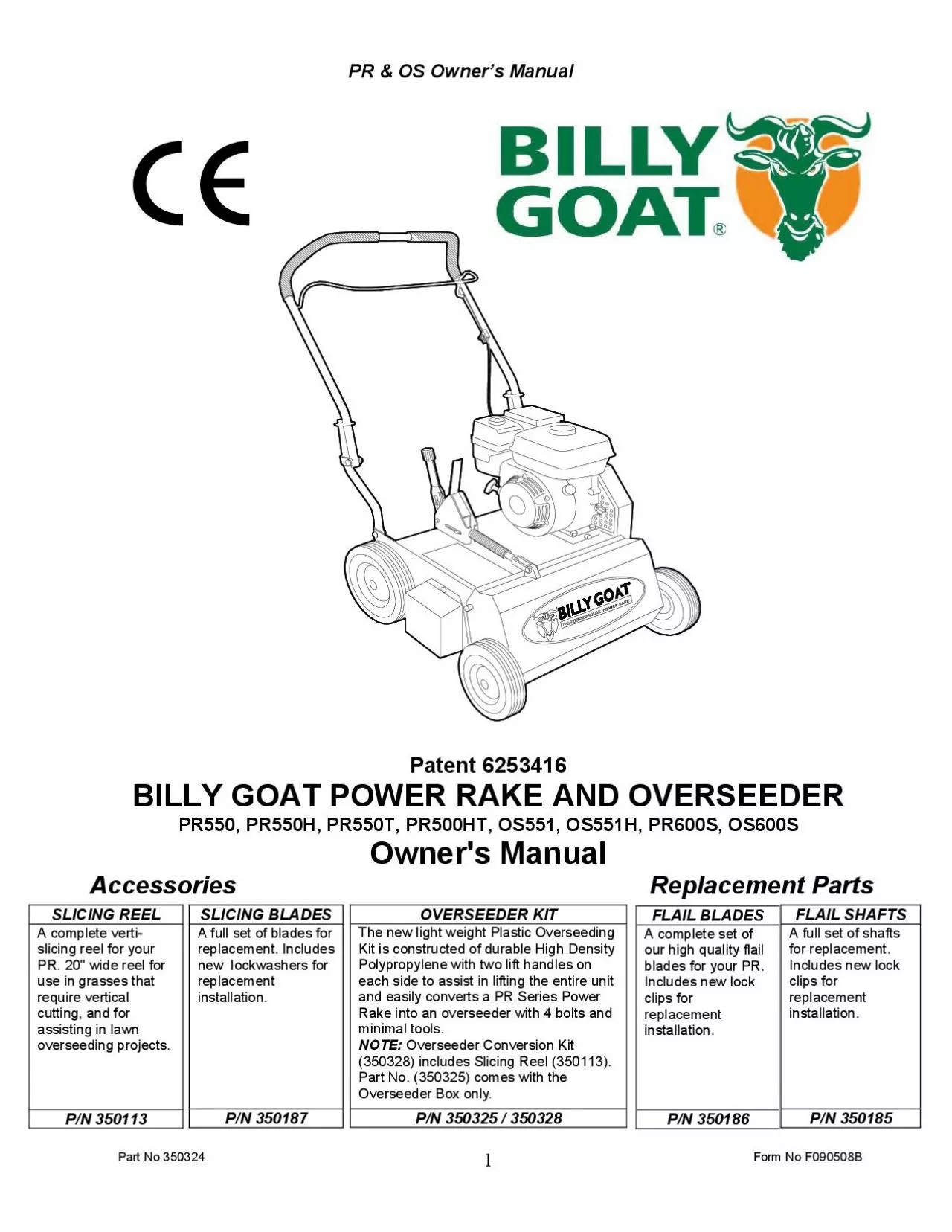
A complete vertislicing reel for your PR 20 wide reel for use in grasses that require vertical cutting and for assisting in lawn overseeding projectsPN 350113 OVERSEEDER KIT The new light weight Pla ID: 856499

part engine reel item engine part item reel blades thatch lock manual unit lawn depth owner parts equipment grass

Share:

Link:

Embed:

Download Presentation from below link

Download Pdf The PPT/PDF document "Part No 350324 Form No F090508B PR OS ..." is the property of its rightful owner. Permission is granted to download and print the materials on this web site for personal, non-commercial use only, and to display it on your personal computer provided you do not modify the materials and that you retain all copyright notices contained in the materials. By downloading content from our website, you accept the terms of this agreement.


Presentation Transcript

1 Part No 350324 Form No F090508B PR & OS
Part No 350324 Form No F090508B PR & OS Owner’s Manual Replacement PartsSLICING REEL A complete verti-slicing reel for your PR. 20" wide reel for use in grasses that require vertical cutting, and for assisting in lawn overseeding projects. P/N 350113 OVERSEEDER KIT The new light weight Plastic Overseeding Kit is constructed of durable High Density Polypropylene with two lift handles on each side to assist in lifting the entire unit and easily converts a PR Series Power Rake into an overseeder with 4 bolts and minimal tools. Overseeder Conversion Kit (350328) includes Slicing Reel (350113). Part No. (350325) comes with the Overseeder Box only P/N 350325 / 350328 FLAIL BLADES A complete set of our high quality flail blades for your PR. Includes new lock replacement P/N 350186 FLAIL SHAFTS for replacement. Includes new lock replacement P/N 350185 SLICING BLADES replacement. Includes new lockwashers for replacement P/N 350187 Part No 350324 Form No F090508BPR & OS Owner’s Manual ABOUT THIS MANUAL THANK YOU for purchasing a BILLY GOAT Power Rake/Overseeder. Your new machine has been carefully designed and manufactured to provide years of reliable and productive service. This manual provides complete operating and maintenance instructions that will help to maintain your machine in top running order. Read this manual carefully before assembling, operating, or servicing your equipment. CONTENTS SERIAL PLATE DATA AND SPECIFICATIONS 3 GENERAL SAFETY 4 SOUND AND VIBRATION 6 INSTRUCTION LABELS 7 PACKING CHECKLIST & ASSEMBLY 8 OPERATION 9-12 MAINTENANCE 13 URE 14 ILLUSTRATED PARTS LIST 15-18 PARTS LIST 19 MAINTENANCE RECORD 20 Part No 350324 Form No F090508B PR & OS Owner’s ManualSERIAL PLATE DATA Record the model number, serial number, date of purchase, and where purchased. Purchase Date: Purchased From:

2 PR550 PR550H O
PR550 PR550H OS551 OS551H PR550T PR550HT PR600S OS600S Engine: HP 5.5 (4.1 kW) 5.5 (4.1 kW) 5.5 (4.1 kW) 5.5 (4.1 kW) 5.5 (4.1 kW) 5.5 (4.1 kW) 6.0 HP (4.7kW) 6.0 HP (4.7kW) Engine: Model 12H1320118B8 GX160T1QX2 12H1320118B8 GX160T1QX2 12H1320118B8 GX160T1QX2 EX17D50012 EX17D50012 Engine: Type B&S VANGUARD HONDA OHV B&S VANGUARD HONDA OHV B&S VANGUARD HONDA OHV SUBARU SUBARU Engine: Fuel Capacity 3.0 qt. (2.84 L) 3.88 qt. (3.6 L) 3.0 qt. (2.84 L) 3.88 qt. (3.6 L) 3.0 qt. (2.84 L) 3.88 qt. (3.6 L) 3.8 qt.(3.6 L) 3.8 qt.(3.6 L) Engine: Oil Capacity 0.66 qt. (0.62 L) 0.69 qt. (0.65 L) 0.66 qt. (0.62 L) 0.69 qt. (0.65 L) 0.66 qt. (0.62 L) 0.69 qt. (0.65 L) 0.63 qt.(0.60 L) 0.63 qt.(0.60 L) Total Unit Weight: 149# (67.7 kg) 147# (66.8 kg) 162# (73.6 kg) 160# (72.7 kg) 139# (63.2 kg) 137# (62.3 kg) 137# (62.3 kg) 137# (62.3 kg) Engine weight: 36# (16.3 kg) 34# (15.4 kg) 36# (16.3 kg) 34# (15.4 kg) 36# (16.3 kg) 34# (15.4 kg) 34# (15.4 kg) 34# (15.4 kg) Max. operating slope 15 20 15 15 20 20 20 20 Sound test in accordance with 2000/14/EC 101 dB(a) 101 dB(a) 101 dB(a) 101 dB(a) 101 dB(a) 101 dB(a) 101 dB(a) 101 dB(a) Sound at operators ear 82 dB(a) 82 dB(a) 82 dB(a) 82 dB(a) 82 dB(a) 82 dB(a) 82 dB(a) 82 dB(a) Vibration at operator position 0.82g (8.04 m/s) 0.82g (8.04 3.2g 3.2g 3.2g 3.2g 3.2g 3.2g Part No 350324 Form No F090508BPR & OS Owner’s Manual GENERAL SAFETY INSTRUCTIONS and SYMBOLSThe safety symbols shown below are used throughout this manual. You should become familiar with them before assembling, operating, or servicing this equipment. This symbol indicates important information that will prevent injury This symbol indicates ear protection is recommended when operating this equipment. This symbol indicates eye protection is recommended when operating this equipment. This symbol indicates gloves should be worn when servicing this equipment. This symbol indicates that this manual and the engine manufacturer’s manual should be read carefully before assembling, operation, or servicing this

3 equipment. This symbol indicates import
equipment. This symbol indicates important information that will prevent damage to your BILLY GOAT Power Rake/Overseeder. This symbol indicates the engine oil level should be checked before operating this equipment. Read and make sure you thoroughly understand the following safety precautions before assembling, operating or servicing this equipment: READ this manual and the engine manufacturer’s manual carefully before assembling, operating, or servicing this equipment. EAR PROTECTION is recommended when operating this equipment. is recommended when operating this equipment BREATHING PROTECTION is recommended when operating this equipment. from this product contains chemicals known to the State of California to cause cancer, birth defects or other reproductive harm. DO NOT operate this equipment on any unimproved forested, brushy, or grass covered land unless a spark arrester is installed on the muffler as required by Section 4442 of the California Public Resources Code. The arrester must be maintained in good working order. Other states may have similar laws. Federal laws apply on federal lands. DO NOT run engine in an enclosed area. Exhaust gases contain carbon monoxide, an odorless and possibly fatal poison. Part No 350324 Form No F090508B PR & OS Owner’s Manual DO NOT run this equipment indoors or in any poorly ventilated area. Refueling outdoors is recommended. DO NOT refuel this equipment while the engine is running. Allow engine to cool for at least two minutes before refueling. DO NOT store gasoline near an open flame. DO NOT remove gas cap while engine is running. DO NOT start or operate engine if strong odor of gasoline is present. DO NOT start or operate engine if gasoline is spilled. Move equipment away from spill until gasoline has completely evaporated. DO NOT smoke while filling the fuel tank. DO NOT check for spark with spark plug or spark plug wire removed. Use an approved spark tester. DO NOT operate engine without a muffler. Inspect muffler periodically and replace if necessary. If equipped with muffler deflector, inspect deflector periodically and r

4 eplace if necessary. DO NOT operate engi
eplace if necessary. DO NOT operate engine with grass, leaves or other combustible material near the muffler. DO NOT touch muffler, cylinder, or cooling fins when hot. Contact with hot surfaces may cause severe burns. DO NOT leave equipment unattended while in operation. DO NOT parkequipment on a steep grade or slope. DO NOT operate equipment with bystanders in or near the work area. DO NOT allow children to operate this equipment. DO NOT operate equipment with guards removed. DO NOT operateequipment near hot or burning debris or any toxic or explosive materials. DO NOT operateequipment on slopes greater than specified in Specifications section of this DO NOT start engine without height adjust lever in up position and clutch bail disengaged. DO NOT place hands or feet underneath unit, or near any moving parts. remove spark plug wire when servicing equipment to prevent accidental starting. check fuel lines and fittings frequently for cracks or leaks. Replace if necessary. keep hands and feet away from moving or rotating parts. store fuel in approved safety containers. Remove all rocks, wire, string, etc. that can present a hazard during work prior to starting. identify and mark all fixed objects to be avoided during work such as sprinkler heads, water valves, buried cables, or clothes line anchors, etc. Part No 350324 Form No F090508BPR & OS Owner’s Manual SOUND LEVEL 82 dB(a) atSound tests were conducted in accordance with 2000/14/EC, and were performed on 2-13-2002 under the conditions listed below. Sound power level listed is the highest value for any model covered in this manual. Please refer to serial plate on the unit for the sound power level for your model.VIBRATION DATA Vibration levels at the operator’s handles were measured in the vertical, lateral and longitudinal directions using calibrated vibration test equipment. Tests were performed on 5-25-2006 under the conditions listed below. This machine is designed for removing thatch from your lawn, renovation of existing lawns, and to assist in overseeding operations. The machine should not be

5 used for any other purpose than that st
used for any other purpose than that stated above. Do not operate if excessive vibration occurs. If excessive vibration occurs, shut engine off immediately and check for damaged or worn reel, loose pulley bolts or set screws, loose engine or lodged foreign objects. (See trouble shooting section on page 14). General Conditions: Sunny Temperature: 48C) Wind Speed: 2 mph (3.2 kmh)Wind Direction: South East Humidity: 29% Barometric Pressure: 30.34Hg (770 mm General Conditions: Sunny Temperature: 72.32C) Wind Speed: 3.8 mph (6.12kph)Wind Direction: East Humidity: 62.2% Barometric Pressure: 29.9Hg (101.3kpa Part No 350324 Form No F090508B PR & OS Owner’s ManualINSTRUCTION LABELSThe labels shown below were installed on your BILLY GOAT Power Rake/Overseeder. If any labels are damaged or missing, replace them before operating this equipment. Item numbers from the Illustrated Parts List and part numbers are provided for convenience in replacement labels. The correct position fo

6 r each label may be determined by referr
r each label may be determined by referring to the Figure and Item numbers shown. LABEL DANGER KEEP HANDS LABEL CLUTCH ITEM #49 DANGER FLYING DEBRIS AND FEET AWAY P/N 830503 ITEM # 48 P/N 810736 ITEM #51 P/N 400424 LABEL CAUTION GUARDS LABEL EXPLOSIVE FUEL LABEL INSTRUCTION HEIGHT ADJ. ITEM #52 P/N 900327 ITEM # 50 P/N 400268 ITEM #35 P/N 350176 LABEL INSTRUCTIONS SEEDER BOX ITEM #45 P/N 350288 ENGINE LABELSHonda Briggs & Stratton Set lever to choke when starting cold Throttle lever Set lever to desired engine speed. Fuel valve Choke lever Move lever completely to the left to stop engine LOW,TELY. OILALERT Part No 350324 Form No F090508BPR & OS Owner’s Manual PACKING CHECKLIST Your Billy Goat Power Rake is shipped from the factory in one carton, completely assembled. PUT OIL IN ENGINE BEFORE STARTING ASSEMBLY READ all safety instructions before assembling unit. TAKE CAUTIONwhen removing the unit from the box the Handle Assembly is attached to the unit by cables. UNFOLD the upper handle (item 26) and slide handle lock loops (item 28) into place to secure the upper handle to the lower. CHECK engine oil level and fill to proper level with engine manufacturers recommended grade of oil. Move height adjust lever to down position, to level engine during checking. See engine manufacturers instruction CONNECT spark plug wire. Boxing Parts Checklist Briggs & Stratton 5.5 B&S VANGUARD Honda 5.5 OHV Subaru 6HP EX17 Literature Assy P/N-430334 PARTS BAG & Warranty card P/N- 400972, Owner’s Manual P/N-350324, Declaration of Conformity P/N-350139. 282828 PR550, PR550H, PR550T, PR550HT, PR600S OS551, OS551H, and OS600S Part No 350324

7 Form No F090508B PR & OS Owner’s Manual
Form No F090508B PR & OS Owner’s Manual Like all mechanical tools, reasonable care must be used when operating machine.Inspect machine work area and machine before operating. Make sure that all operators of this equipment are trained in general machine use and safety. PUT OIL IN ENGINE BEFORE STARTINGSTARTING ENGINE: See engine manufacturer’s instructions for type and amount of oil and gasoline used. Engine must be level when checking and filling oil and gasoline. FUEL VALVE: Move fuel valve to "ON" position (when provided on engine). Located on the engine. "ON" position. CHOKE: Operated with choke lever on side of engine. THROTTLE: Controlled by throttle lever on the motor. IF YOUR UNIT FAILS TO START: See Troubleshooting on page 14. HANDLING & TRANSPORTING: This unit requires two people to lift it. With the handle in the folded position, lift holding the lower handle and belt/shaft guard one on each side of the machine. Secure the machine in place during transport. See page 3 for weight specifications Never lift the machine while the engine is running. ADJUSTING BLADE DEPTH The depth of the blades can be raised or lowered byrotating the knob on the top of the adjustment lever. The blades are lowered by rotating the knob clockwise, and raised by rotating the knob counter-clockwise. The relative depth of the blades can be gauged by using the depth scale located on the right front corner of the engine base. With new blades installed the depth can be estimated as follows: 2.5 on the scale is even with the ground, is equal to 0.25" deep, and is equal to 0.5" deep FOLDING HANDLE This unit is equipped with a folding upper handle for easier storage and transportation. The handle can be folded by sliding the handle lock loops (item 28) up. This releases the upper handle, allowing it to be folded over the unit. BLADE POSITION & DEPTH CONTROL LEVER The blades can be raised or lowered into the ground by height adjustment lever on the engine base. The height adjuster lock lever must be pushed back against the adjustment lever in order to lower the blades into the g

8 round. The resulting blade depth can be
round. The resulting blade depth can be adjusted higher or lower. See ADJUSTING BLADE DEPTH. clockwise to lower bladescounter clockwise to raise blades blades uptransportblades uptransportblades down running SPRING TINE CONVERSION If are converting your Power rake to a spring tine reel, you will need to replace the spacer on the control lever to accommodate for the tine. First remove the clip (item 18), then unscrew the yoke (item 17), remove the washer (items 69) and insert the spacer (item 75) in front of the spring. Reassemble in reverse order. Part No 350324 Form No F090508BPR & OS Owner’s Manual RAKING/SLICING TIPS Before beginning, it is best to evaluate the condition of the lawn by cutting one or more core samples from area to be treated. A core can be cut using a piece of pvc, or metal pipe. Hammer the pipe into the ground, remove it, push the core out of the pipe and inspect it to determine the depth of thatch in your yard. THATCH: Thatch is a dense layer of dead grass, clippings, and roots that builds up over time at the base of of the lawn preventing air, water, and fertilizer from reaching the soil. This can cause shallow root development and make a lawn more susceptible to drought and disease. Thatch also provides an ideal environment for insects to hide and multiply. Periodic removal of thatch will keep your lawn in good health. HEAVY THATCH: Lawns with an excessive amount of thatch will require multiple treatments for effective removal. Trying to remove excessive thatch (greater than 3/4"[19 mm] deep) in one treatment will damage or destroy the living part of the lawn. It is best to remove heavy thatch in seasonal treatments (i.e. spring, and fall). Rake slopes across not up and down. This is much easier and safer for the operator and is better for the lawn. Raking across will help to reduce runoff during watering and allow the sloped ground to hold more seed, fertilizer, and water. The units maximum operating slope is 35% or 19°. The wide range of depth adjustment on your unit is provided to allow for blade wear. Setting the reel deeper

9 will not produce better, or quicker res
will not produce better, or quicker results. The flail reel is intended to be set so it just touches the surface on flat ground. The slicing reel should be set even with the ground for verti-slicing work, and set to a maximum 1/2" depth for overseeding jobs. Setting the reel deeper than this will only result in premature wear on the unit (i.e. failed belt). If you desire to work the ground deeper than the above guidelines allow, it should be done gradually in multiple passes.. SLICING / OVERSEEDING: Mow the lawn to shorter than the normal cut height before starting (i.e. approximately 2" tall for fescue grass). For the best result, Slice/Overseed in criss-cross pattern (See Fig. 1 and See Fig 2). RAKING OPERATION-FLAIL REEL NOTE: Must have the flail reel assembly (350112) for this operation. Mow the lawn to it's normal cut height. Be sure grass is dry. Wet conditions can cause increased damage to healthy grass. With engine off, set the raking depth so that the blades just touch on a flat surface (i.e. driveway, or sidewalk).START ENGINE: See page 9 for further instruction. ENGAGE BLADES: Pull back on the bail on the operators handle. When engaging the blades in heavy load conditions (i.e. heavy thatch, or very uneven turf), push down on the operators handle lifting the front wheels slightly. Engage the blades. Slowly lower the unit into RAKE: Rake a small test area and examine the results. Thatch should be removed and deposited on top of the healthy grass. If excessive damage occurs to healthy grass, adjust the blade depth to decrease damage. Continue raking the yard, working in one direction (i.e. north-south, or east-west). If a large drop in engine RPM occurs, or the unit pulls you forward and bounces during operation the blade depth is set too low. REMOVE THATCH: After raking, a layer of thatch will be deposited over the top of the lawn. This thatch must be removed prior to any fertilizing, seeding, or watering of the lawn. We suggest the use of a lawn vacuum or wheeled blower for collection and removal of the thatch. Fig. 1 Part No 350324 Form No

10 F090508B PR & OS Owner’s ManualRAKING O
F090508B PR & OS Owner’s ManualRAKING OPERATION-SPRING REEL NOTE: Must have the spring tine reel assembly (350354) for this operation. Mow the lawn to it’s normal cut height. Tall grass will not leave a manicured look when the dethatching job is complete. Be sure grass is relatively dry. Wet conditions can cause increased damage to healthy grass. With engine off, set the raking depth so that the spring tines are just above touching the flat surface (i.e. driveway, or sidewalk) the units height is being adjusted on. Allowing the spring tines to have substantial contact with the ground will cause premature wear and failure of the START ENGINE: See page 9 for further instruction. ENGAGE TINES: Pull back on the bail on the operators handle. When engaging the spring tines in heavy load conditions (i.e. heavy thatch, or very uneven turf), push down on the operators handle lifting the front wheels slightly. Engage the spring tines. Slowly lower the unit into the turf. RAKE: Rake a small test area and examine the results. Thatch should be removed and deposited on top of the healthy grass. If excessive damage occurs to healthy grass, adjust the spring tine depth to decrease damage. Continue raking the yard, working in one direction (i.e. north-south, or east-west). If a large drop in engine RPM occurs, or the unit pulls you forward and bounces during operation the spring tine depth is set too low. REMOVE THATCH: After raking, a layer of thatch will be deposited over the top of the lawn. This thatch must be removed prior to any fertilizing, seeding, or watering of the lawn. We suggest the use of a lawn vacuum or wheeled blower for collection and removal ofthe thatch. VERTI-CUTTING OPERATION NOTE: Must have the slicing reel assembly (350113) for this operation. Mow the lawn to shorter than the normal cut height (approximately 2" tall) Be sure grass is dry. Wet conditions can cause increased damage to healthy grass. With engine off, set the raking depth so that the blades just touch on a flat surface (i.e. driveway, or sidewalk).START ENGINE: See Page 9. ENGAGE BLADES

11 : Pull back on the bail on the operators
: Pull back on the bail on the operators handle. When engaging the blades in heavy load conditions (i.e. heavy thatch, or very uneven turf), push down on the operators handle lifting the front wheels slightly. Engage the blades. Slowly lower the unit into the Verti-cut a small test area and examine the reand cut stems should be removed and deposited on top of the healthy grass. Grass runners should be cut and ready for removal. If excessive damage occurs to healthy grass, adjust the blade depth to decrease damage. Continue raking the yard, working in one direction (i.e. north-south, or east-west). If a large drop in engine RPM occurs, or the unit pulls you forward and bounces during operation the blade depth is set too low. REMOVE THATCH/STEMS: After verti-cutting, a layer of thatch and cut stems will be deposited over the top of the lawn. We suggest the use of a lawn vacuum or wheeled blower for collection and removal of the thatch/stems. OVERSEEDING OPERATION NOTE: Must have the slicing reel assembly (350113) for this operation. Mow the lawn to shorter than the normal cut height (approximately 2" tall) Be sure grass is dry. Wet conditions can cause increased damage to healthy grass. Spread grass seed according to the seed suppliers directions (e.g. 10 lbs. per 1000 ft00 ftkg. per 93 m2 ]) SET DEPTH: With engine off, set the raking depth so that the blades reach 1/4"-1/2"(6-12 mm) below a flat surface (i.e. driveway, or sidewalk).START ENGINE: See Page 9. ENGAGE CLUTCH: Pull back on the bail on the operators handle. When engaging the clutch in heavy load conditions (i.e. heavy thatch, or very uneven turf), push down on the operators handle lifting the front wheels slightly. Engage the clutch. Slowly lower the unit into the turf. Run machine over the area that has been seeded to incorporate the seed into the soil. If excessive damage occurs to healthy grass, adjust the blade depth to decrease damage. Continue raking the yard, working in one direction (i.e. north-south, or east-west). If a large drop in engine RPM occurs, or the unit pulls you forward and boun

12 ces during operation the blade depth is
ces during operation the blade depth is WATER/FERTILIZE: After the seed has been worked into the soil, water and fertilize according to the seed suppliers directions. Part No 350324 Form No F090508BPR & OS Owner’s Manual SETTINGSTOP ADJUSTING SEED RATE - PULL BACK ON THE KNOB THEN SLIDE THE BRACKET TO DESIRED STOP SETTING.EXAMPLE: STOP SETTING IS ON 4- IF SLICING WITHOUT DROPPING SEEDS FOR LONG PERIOD THEN SET THE STOP SETTING TO ZERO. LAWN PREPARATION - MOW LAWN TO LOWEST SETTING ON YOUR MOWER. - DO NOT WATER PRIOR TO SEEDING. - POWER RAKE TO DETHATCH LAWN AND REMOVE THATCH.- FERTILIZE LAWN WITH BROADCAST SPREADER. LAWN PREPARATION - FOR BEST RESULTS OVERSEED IN TWO PASSES OF ONE-HALF APPLICATION RATE EACH, AT RIGHT ANGLES OR IN A CRISS-CROSS PATTERN.- WATER HEAVILY IMMEDIATELY THEN LIGHTLY FOR 10 - 14 DAYS, KEEPING SOIL MOIST. - AFTER GERMINATION, WATER LESS OFTEN TO PROMOTE ROOT GROWTH. DROPPING SEEDS -AFTER ADJUSTING THE STOP SETTING, LIFT UP ON THE BAR TO OPEN THE DROP SEEDER - TO STOP DROPPING SEEDS, PUSH FORWARD ON THE HANDLE TO CLOSE THE DROP SEEDER NOTE: IF SLICING WITHOUT DROPPING SEEDS FOR LONG PERIOD OF TIME THEN SET THE STOP SETTING TO ZERO. LBSRATE1,000 FTFASTER TRAVEL DELIVERS LESS SEED.THESE SETTINGS ARE APPROXIMATE GUIDELINES. SEEDING RATES ARE SPEED DEPENDENT.1/21 1/22 1/33/42 1/21 1/23/41 1/43/4 3 1/2FESCUEBLUEGRASSRYEGRASSTYPESEED(ALL DROPMODELS)(HULLED & ZOYSIA)1 2/3(COATED)CENTIPEDEGRASSST. AUGUSTINEGRASS3/41 1/21 1/31 1/42 1/22/315 1/26 1/3SEED APPLICATION CHART:1,000 FTTYPESEEDBENTGRASSBERMUDAGRASSSETTINGSTOP3/42/31 1/3RATELBSREFERENCESETTINGSEEDERGOATBILLYSETTINGSTOPSCOTTSSEEDERSETTING Part No 350324 Form No F090508B PR & OS Owner’s ManualERIODIC AINTENANCEPeriodic maintenance should be performed at the following intervals:Maintenance Operation Every Use (daily) Every 25 Hours Inspect for loose, worn or damaged parts. Check engine oil Inspect belt Engine (See Engine Manual) Grease reel bearings Inspect and clean engine air filter Oil height adjustment linkage FLAIL BLADE WEAR Wait for engine to c

13 ool and disconnect spark plug. . Close
ool and disconnect spark plug. . Close fuel valve on engine (if available). Lean unit back onto lower handles and secure in place. . Inspect blades for wear, and immediately replace any bent or cracked blades. Measure the overall length of the blade. (See fig. 1) If blades measure less than 3.25"(83 mm) in overall length they must be replaced. NOTE: We recommend replacing all the flails at once. SLICING BLADE WEAR Wait for engine to cool. Close fuel valve on Lean unit back onto lower handles and secure in place. . Inspect blades for wear, and immediately replace any bent or cracked blades. Measure the overall length of the blade from the center of the attachment bolt to the tip of the worn If blades measure less than 3"(76 mm) in length they must be replaced. NOTE: We recommend replacing all the blades at once. ROTATING FLAIL REEL END TO ENDTo maximize flail blade life and performance the reel can be rotated end to end periodically to provide a fresh lead cutting edge. Takes approx. 20 min. and requires 1/2" and 9/16" socket wrenches with extension bar. Wait for engine to cool and disconnect spark plug. . Close fuel valve on engine (if available). Lean unit back onto lower handles and secure in place. . Remove (7) lock nuts (item 62 & 40) holding the belt and shaft guards (item 21 & 22) in place. It is necessary to lower the height adjust lever to reach the locknuts on the guards. Remove the guards.Remove the drive belt (item 9) by "walking" it out of the groove on the reel pulley (item 2). Remove the (4) lock nuts (item 60) and washers (item 68) holding the bearings (item 23) to the frame of the unit. The reel is now free from the machine. Slide the reel down and out of the machine. Remove the capscrew (item 71), lockwasher (item 57), reel pulley (item 2), key (item 42), and reel spacer (item 10) from the end of the reel. Rotate the reel end to end, and re-install these items on the opposite end of the reel. Re-install the reel in reverse order of removal. Re-install the guards in reverse order of removal. DRIVE BELT REPLACEMENT NOTE: Takes approx. 10 min.

14 and requires 1/2" socket wrench with ex
and requires 1/2" socket wrench with extension. Wait for engine to cool and disconnect spark plug. Remove (4) lock nuts (item 62) holding the belt guard (item 21) in place. It is necessary to lower the height adjust lever to reach the locknuts on the guard. Remove the guard. Remove the belt (item 9) by rotating the reel pulley (item 2) and walking it out of the groove. Discard old belt . Install new belt using same procedure to walk the belt into the groove. With new belt installed pull bail rod back to engaged position and measure extension of idler spring. Spring should stretch 3/4" - 1" (19 25 mm) with bail engaged. Adjust clutch cable as necessary to achieve this extension. Fig. 1 Part No 350324 Form No F090508BPR & OS Owner’s Manual Never store engine indoors or in enclosed poorly ventilated areas with fuel in tank, where fuel fumes may reach an open flame, spark or pilot light, as on a furnace, water heater, clothes dryer or other gas appliance. If engine is to be unused for 30 days or more, prepare as follows: Remove all gasoline from carburetor and fuel tank to prevent gum deposits from forming on these parts and causing possible malfunction of engine. Drain fuel outdoors, into an approved container, away from open flame. Be sure engine is cool. Do not smoke. Run engine until fuel tank is empty and engine runs out of gasoline.When servicing engine refer to specific manufacturers engine owner's manual. Engine warranty is covered by the specific engine manufacturer. If your engine requires warranty or other repair work contact your local servicing engine dealer. When contacting a dealer for service it is a good idea to have your engine model number available for reference (See table page 3). If you cannot locate a servicing dealer in your area you can contact the manufacturers national service organization. To reach:American Honda: 800-426-7701 WARRANTY CLAIM PROCEDURE Should a BILLY GOAT machine fail due to a defect in material and/or workmanship, the owner should make a warranty claim as follows: The machine must be taken to the dealer from whom

15 it was purchased or to an authorized Se
it was purchased or to an authorized Servicing BILLY GOAT Dealer. The owner must present the remaining half of the Warranty Registration Card, or, if this is not available, the The Warranty Claim will be completed by the authorized BILLY GOAT Dealer and submitted to their respective BILLY GOAT Distributor for their territory Attention: Service Manager. Any parts replaced under warranty must be tagged and retained for 90 days. The model number and serial number of the unit must be stated in the Warranty Claim. The distributor service manager will sign off on the claim and submit it to BILLY GOAT for consideration. The Technical Service Department at BILLY GOAT will study the claim and may request parts to be returned for examination. BILLY GOAT will notify their conclusions to the distributor service manager from whom the claim was received. The decision by the Technical Service Department at BILLY GOAT to approve or reject a Warranty Claim is final and binding. ProblemPossible CauseSolutionAbnormal vibration.· Damaged or missing blades. Loose handle bolts. Loose engine bolts· Stop work immediately. Replace any damaged or missing blades. Tighten all loose nuts and bolts.Engine stalls or labors when raking· Blades set too deep into ground.· Raise blades so that they just touch the ground on a level surfaceEngine will not start.· Stop switch off (Honda only). Throttle in off position· Check choke position.· Out of gasoline or bad, old gasoline.· Check gasoline.· Spark Plug wire disconnected.· Connect spark plug wire.· Gas valve off.· Turn on gas valve.· Dirty air cleaner.· Clean or replace air cleaner. Contact a qualified service person.Engine is locked, will not pull over.· Debris locked against reel, or drive pulleys. Engine problem.· Pull spark plug wire and remove debris. Contact an engine servicing dealer for engine problems. Part No 350324 Form No F090508B PR & OS Owner’s Manual PARTS LISTITEM NO.PART NO.DESCRIPTIONQTY1350366BOX AND LID ASSEMBLY2350306BRACKET ADJ DROP SEEDER ASSY13350276BAR DOOR LINKAGE14350320SHAFT PLASTIC DROP SEEDER15350271PLATE DOOR DROP SEEDER1635

16 0272PLATE DOOR DROP SEEDER END17350273PL
0272PLATE DOOR DROP SEEDER END17350273PLATE DOOR DROP SEEDER ARM19350370PULLEY 3V GROOVE 0.625" BORE1108171003WASHER 5/16 FLAT CUT111900321BEARING CLIP 1.375 OD413400217SPRING TENSION2148024040BOLT CARRIAGE 5/16 - 18 X 11158024021BOLT CARRIAGE 1/4-20 X 3/4"1168123087SCREW SELF TAP #10-24 X 3/8" HMS ZP4178160001NUT LOCK 1/4118350332BRACKET SLOT PLASTIC SEEDER BOX1198160002NUT LOCK 5/16121350369PULLEY 3V GROOVE 1.530" BORE122350280WASHER 0.906 O.D. X 0.656 I.D. X 0.0627-824350372BELT O-RING 5/16 X 15 9/16"1258197031PIN COTTER 1/8" X 1"1269195106ROLL PIN 1/8 - 1 1/41288172007WASHER 1/4 SAE1298154007NUT HEX 10-242308059136SCREWCAP #10-24 X 3/4232350288LABEL INSTRUCTION SEEDER BOX133890456LABEL HOSE PLUG KD/SV134350313LABEL PRODUCT DECAL OS1 PARTS BAG SEEDER BOX KIT 350326198160002NUT LOCK 5/16 (REQUIRE ON THE OLD MODELS ONLY)4208177011WASHER LOCK 5/164238041026SCREWCAP 5/16-18 x 3/44278172020WASHER 5/16 FENDER431900230WASHER 1/2 FC1-2328161044NUT LOCK 1/2" THIN HGT1-350327LIT SEEDER BOX (INCLUDES TEMPLATE)1 Part No 350324 Form No F090508BPR & OS Owner’s Manual HAFT KIT 350 1 FLAIL BLADE KIT 350 1 SPACER BUMPER KIT 350258 SLICING BLADE KIT 350187 FLAIL REEL KIT 350 112 PARTS DRAWING item PARTS QTYno. LIST Part No.57LOCK WASHER TWISTED TOOTH400502171SCREWCAP REEL PULLEY8041050173SHAFT FLAIL BLADE350141474BLADE FLAIL3501003076SPACER BUMPER 5/8" x 1/2"3501445477SHAFT WA FLAIL REEL350145178CLIP LOCK 1/2"350146879WASHER 1/2 SAE81720118 item PARTS Part No.QTYno. LIST 73SHAFT FLAIL BLADE350141478CLIP LOCK 1/2"3501468 item PARTS Part No.QTYno. LIST 74BLADE FLAIL3501006078CLIP LOCK 1/2"3501468 item PARTS no. LIST Part No.76SPACER BUMPER 5/8" x 1/2"35014454 item PARTS LIST QTYPart No.

17 81BLADE 10" HEX SLICING 3501472085SCREW
81BLADE 10" HEX SLICING 3501472085SCREWCAP 1/4-20 X 3/4 HCS ZP80410044086NUT LOCK 1/4-20814200440 Part No 350324 Form No F090508B PR & OS Owner’s Manual SLICING REEL ASSY 350113 SPRING TINE REEL ASSY - 350355-S SPRING REPLACEMENT KIT -350356-SPARTS DRAWING ite PARTS Part No.QTYno. LIST 1SHAFT WA SPRING TINE REEL35035312SHAFT SPRING TINE REEL35035143SPRING TINE3503521084RING RETAINING 1/2"35014685SCREWCAP 5/16"-24x1" GR. 5 ZP40016416WASHER LOCK TWISTED TOOTH HEAVY4302981 item PARTS QTYno. LIST Part No.3SPRING TINE3503521084RING RETAINING 1/2"3501468 item PARTS PR500QTYno. LIST Part No.57LOCK WASHER 5/16 TWISTED TOOTH800177171SCREWCAP 5/16 - 24 x 1" HCS GR. 5400164180SHAFT SLICING WA350142181BLADE SLICING REEL3501472082PLATE BLADE MTG.3501482083SPACER BLADE MTG.3501491084SPACER BLADE ASSY350150985SCREWCAP 1/4-20 x 3/4, HCS ZP80410044086NUT LOCK 1/4-2081420044087COLLAR SPACER350152188WASHER 0.937 x 1.750 x 0.119350153189WASHER LOCK 7/8 INT. TOOTH350154190NUT JAM 7/8-143501551 Part No 350324 Form No F090508BPR & OS Owner’s Manual PARTS DRAWING PR550, PR550H, PR550T, PR550HT, PR600S, OS551, OS551H, OS600S Part No 350324 Form No F090508B PR & OS Owner’s ManualPARTS LIST 75SPACER 1/2" ID X 3/4"--------35036353503635----76WASHER 3/8 SAE817200928172009281720092817200928172009281720092817200928172009277NUT PAL 3/83602182360218236021823602182360218236021823602182360218278WASHER 1/4 FLAT CUT817100218171002181710021817100218171002181710021817100218171002179PIN CLEVIS 3/8" X 1.6255201192520119252011925201192520119252011925201192520119280RETAINER 3/8" BOLT PUSH NUT36027923602792360279236027923602792360279236027923602792 item PARTS PR550QTYPR550HQTYOS551 QTYOS551HQTYPR550TQTYPR550HTQTYPR600SQTYOS600SQTYno. LIST

18 Part No.Par
Part No.Part No.Part No.Part No.Part No.Part No.Part No.Part No.1Pulley 3" OD350101135010113501011350101135010113501011350101135010111ASpacer Crank PR Honda350339135033913503391350339135033913503391350339135033912Pulley 6.5" OD X ¾"350102135010213501021350102135010213501021350102135010213WHEEL 8.0" X 5/8" BEARING350103235010323501032350103235023623502362350103235010324WHEEL 10.0" X 5/8" BEARING350104235010423501042350104235036223503622350104235010425Height Adjust Assy350107135010713501071350107135010713501071350107135010716Reel Flail / Slicing / Spring Assy350112135011213501131350113135035413503541350354135011317Pulley Idler 2.75"35011413501141350114135011413501141350114135011413501141 A rm Idler WA350115135011513501151350115135011513501151350115135011519Belt 5L X 363501161350116135011613501161350116135011613501161350116110Spacer Reel Pulley3501181350118135011813501181350118135011813501181350118111Bracket Mount Clutch Cable3501191350119135011913501191350119135011913501191350119112Chassis WA W/ Label3501941350194135019413501941350194135019413501941350194113Frame Front WA3501211350121135012113501211350121135012113501211350121114Bushing 0.375 OD X 0.256 ID X 0.883503091350309135030913503091350309135030913503091350309115Spring Height Adjust PR5003501251350125135012513501251350125135012513501251350125116Link Height Adjust PR50035012613501261350126135012613501261350126135012613501261 oke ½ - 203501271350127135012713501271350127135012713501271350127118Pin Yoke ½"3501281350128135012813501281350128135012813501281350128119Bracket Mount Hgt. Adj. WA3501821350182135018213501821350182135018213501821350182120Spacer Spanner Wheel PR5003501304350130435013043501304----3501304350130421Guard Belt WA W/ Label3501951350195135019513501951350195135019513501951350195122Guard Shaft WA W/ Label3501961350196135019613501961350196135019613501961350196123Bearing ¾" Cast Pillow Block3501332350133235013323501332350133235013323501332350133224Handle Lower LH WA3501341350134135013413501341350134135013413501341350134125Handle Lower RH WA35013513501351350135135013513501351350135135

19 01351350135126Handle Upper PR50035037513
01351350135126Handle Upper PR5003503751350375135037513503751350375135037513503751350375127Bail Clutch WA3503741350374135037413503741350374135037413503741350374128Loop Folding Handle3501382350138235013823501382350138235013823501382350138229Deflector Rubber3501671350167135016713501671350167135016713501671350167130Shield Bearing3501682350168235016823501682350168235016823501682350168231Bar Clamp Deflector3501711350171135017113501711350171135017113501711350171132Bracket Height Adjust Lock WA3501731350173135017313501731350173135017313501731350173133Guard Pulley Back3501841350174135018413501741350184135017413501741350174134Lever Height Control3501751350175135017513501751350175135017513501751350175135Label Instr. Hgt. Adj.3501761350176135017613501761350176135017613501761350176136Bolt Shoulder ¼" x 1 ¾"3501781350178135017813501781350178135017813501781350178137Bolt Shoulder 5/16" x 1 ¾"3501791350179135017913501791350179135017913501791350179138Cable Clutch Reel PR5003501811350181135018113501811350181135018113501811350181139Spring Extension4002171400217140021714002171400217140021714002171400217140BOLT SHOULDER 1/2" X 1"5001141500114150011415001141500114150011415001141500114141ENGINE HONDA 5.5 H.P. GX160--6001151--6001151--6001151----ENGINE 5.5 HP B&S VANGUARD3503791--3503791--3503791------ENGINE SUBARU 6HP EX17------------3503071350307142KEY 3/16" X 1"920107829201078292010782920107829201078292010782920107829201078243GRIP 1" x 13"4005702400570240057024005702400570240057024005702400570244GRIP LEVER 1/8 x 1 x 5"5001811500181150018115001811500181150018115001811500181145LABEL INSTRUCTION SEEDER BOX----35028813502881350288147FINGER BELT WIRE3503011350301135030113503011350301135030113503011350301148LABEL DANGER THROWN OBJECT8107361810736181073618107361810736181073618107361810736149LABEL CLUTCH VQ8305031830503183050318305031830503183050318305031830503150LABEL HOT ENGINE4002681400268140026814002681400268140026814002681400268151LABEL WARNING4004242400424240042424004242400424240042424004242400424252LABEL DANGER GUARD9003271900327190032719003271900327190032719003271900327153PLUG CAP 1" RD89013228901

20 3228901322890132289013228901322890132289
32289013228901322890132289013228901322890132254BOLT CARRAIGE 3/8-16 x 1 3/4802406148024061480240614802406148024061480240614802406148024061455BOLT CARRAIGE 5/16-18 x 1 3/4802404328024043280240432802404328024043280240432802404328024043256BOLT CARRIAGE 5/16 -18 x 3/4802403948024039480240395802403958024039580240395802403958024039557LOCK WASHER TW. TOOTH4005021400502180017718001771800177180017714005021800177158NUT LOCK #10-24816400518164005181640051816400518164005181640051816400518164005159NUT LOCK 1/4-20816000128160001281600015816000158160001581600015816000158160001560NUT LOCK 3/8-16816000398160003981600039816000398160003981600039816000398160003961NUT LOCK 3/8-16 THIN816104238161042381610423816104238161042381610423816104238161042362NUT LOCK 5/16-1881600021881600021881600021981600021981600021981600021981600021981600021963SCREWCAP 1/4-20 x 1 1/2804100818041008180410081804100818041008180410081804100818041008164SCREWCAP 3/8 - 16 x 1 1/2804105218041052180410521804105218041052180410521804105218041052165SCREWCAP 5/16-24 x 3/4" GR.5804202638042026480420263804202648042026380420264804202648042026465AWasher 3/4 SAE817201518172015181720151817201518172015181720151817201518172015165BWasher 5/16 Twist Tooth4302981430298143029814302981430298143029814302981430298166SCREWCAP 5/16 - 18 x 1 1/2804103048041030480410304804103048041030480410304804103048041030467SCREWCAP 5/16-24 X 14001641400164140016414001641400164140016414001641400164168WASHER 3/8 FLAT CUT817100488171004881710048817100488171004881710048817100488171004869WASHER 1/2 SAE ZP817201128172011281720115817201158172011581720115817201158172011570NUT LOCK 1/2" - 13 THIN HGT816104448161044481610444816104448160005481600054816000548161044471SCREWCAP REEL PULLEY8041050180410501400164140016414001641400164180410501400164172BUTTON SOCKET 5/16-18X5/8”35026643502664----350266435026643502664--73BOLT SHOULDER 1/2" x 2"5200312520031252003125200312520031252003125200312520031274FLANG SCREW 0.375 -16 X 0.7579108027910802791080279108027910802791080279108027910802 Part No 350324 Form No F090508BPR & OS Owner’s Manual MAINTENANCE RECORDDate Service Perfor