/
Designing Tough Carbon Nanotube Fibers Designing Tough Carbon Nanotube Fibers

Designing Tough Carbon Nanotube Fibers - PowerPoint Presentation

mitsue-stanley
mitsue-stanley . @mitsue-stanley
Follow
414 views
Uploaded On 2017-08-11

Designing Tough Carbon Nanotube Fibers - PPT Presentation

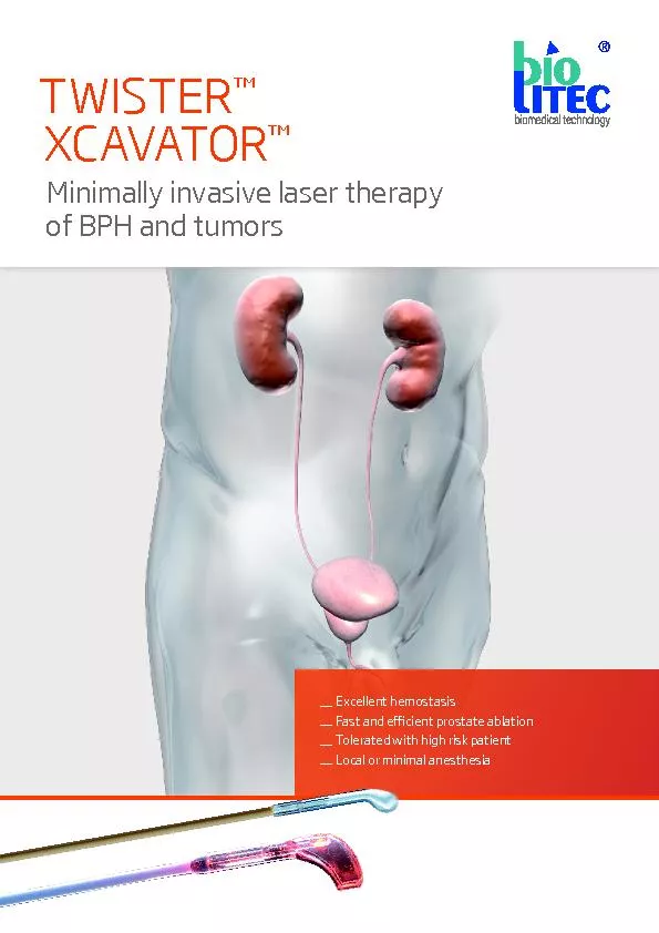
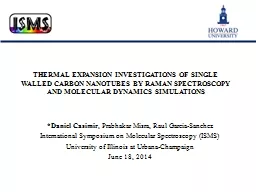
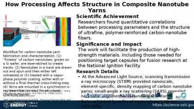
LAMMPS Users Workshop August 911 2011 Sandia National Laboratories Albuquerque NM DISTRIBUTION STATEMENT A Approved for public release distribution is unlimited   Charles F Cornwell ID: 577910

fiber cnt cross stress cnt fiber stress cross fibers strain length strength gpa prof simulations material carbon materials design

Share:

Link:

Embed:

Download Presentation from below link

Download Presentation The PPT/PDF document "Designing Tough Carbon Nanotube Fibers" is the property of its rightful owner. Permission is granted to download and print the materials on this web site for personal, non-commercial use only, and to display it on your personal computer provided you do not modify the materials and that you retain all copyright notices contained in the materials. By downloading content from our website, you accept the terms of this agreement.


Presentation Transcript

Slide1

Designing Tough Carbon Nanotube FibersLAMMPS User’s Workshop August 9–11, 2011Sandia National LaboratoriesAlbuquerque, NM

DISTRIBUTION STATEMENT A Approved for public release; distribution is unlimited


Charles F. Cornwell

US

Army Engineer Research and Development Center

3909 Halls Ferry Road

Vicksburg, MS 39180 Slide2

Designing Tough Carbon Nanotube FibersMaterials Research from Nanoscale to Macroscale

Dr.

Charles Cornwell

Leader

Atomistic Simulation Team

Information Technology Laboratory,

US Army Engineer Research and Development Center

Vicksburg, MSSlide3

ERDC Researchers: Dr. Bob Ebeling (Team Lead-Structural Concepts), Dr. Charles Marsh (Team Lead-Material Synthesis), Dr. Charles Cornwell (Team Lead – Atomistic Modeling), Dr. Mei Chandler, Toney Cummins, Dr. Paul Allison, Clint Arnett, Dr. N. Jabari Lee, Dr. James Baylot, Dr. Bryce Devine, Dr. Fran Hill, Thomas Carlson, Dr. Kevin Abraham, Pete Stynoski, Thomas Hymal, Jonathan George, Ben Ulmen, Dr. Meredith C.K. Sellers, Kyle Ford, Erik

Wotring

, Dr. Jeff Allen, Dr. Laura

Walizer

Natick Collaborators:

Claudia Quigley, Karen Buehler, Dr. Mike SennettNASA Collaborators: Dr. Richard Jaffe (NASA Ames), Dr. Mike Meador (NASA Glenn)Rice U. Collaborators: Prof. Matteo Pasquali, Nobel Laureate Prof. Robert Curl, Prof. Robert Hauge DTRA Collaborators: Dr. Jeffrey DePriest, Dr. Heather MeeksMIT/ISN Collaborators: Prof. Mike Strano, Prof. Markus BuehlerU. of Illinois/Champaign Collaborators: Prof. Parimita Mondal, Prof. Waltrude Kriven, Prof. Alexi Bezryadin ARL Collaborators: Dr. Daphne Papas, Dr. Michelle FleischmanARO MURI Team Collaborators: Dr. David Stepp, Dr. Doug Kiserow, Northwestern U., othersImperial College/Queen Mary College: Prof. Eduardo Saiz, Prof. Mike Reece (funded/coordinated through Army International Research Office, Dr. Steve Grant)DoD HPCMO PETTT-funded Collaborators: Prof. Susan Sinnott (U. FL); Prof. Steve Stuart (Clemson U.); Prof. Anthony Rollett (Carnegie Mellon U.)

Program Managers – Dr. Bob Welch and Dr. John Peters

Advanced Materials Initiative - Research TeamSlide4

OverviewMotivationCNT FibersCNT Fibers with Cross-linksCNT Fiber Post-yieldCurrent Work (Ceramics)Slide5

Military and Civil Engineering are

dependent on 3 areas:

Newtonian (Classical) Mechanics – static.

Policies and procedures – slowly changing.

Materials – potential orders-of-magnitude improvement.

Requires taking advantage of nanoscale material properties.Requires building to molecular design.Materials underpin almost all technology…. Portions of human history are named for the predominant materials of the day.Slide6

Goal: Develop carbon nanotube (CNT)-based 1-million-psi tensile material (filaments, membranes) to Technology Readiness Level 4 (laboratory demo). This would be a major accomplishment:

Results in material with 2X strength/weight ratio of Kevlar and 5X tensile strength of very high strength steel (4340 alloy).

Inaugurates a paradigm shift in material development.

Lays the technical foundation for rapid development of other “super” materials and materials by design.

Molecular dynamics simulation of a hexagonal closest-packed bundle of carbon nanotubes

Initial Super Materials ProgramCarbon Nanotube-Based Filaments, Membranes, CoatingsSlide7

Some ERDC Scientific Contributions fromMolecular Dynamics Simulations

van der Waals forces are asymptotic

No critical length.

(Cornwell et al., 2008)

MD Simulations Using Statistical Models of Molecular Constructs

(Cornwell et al., 2009)Defects and CNT tensile strength; brittle behavior of most CNTs (predicted Haskins et al., 2007; validated Peng et al., 2008)Methods to overcome CNT brittle behavior by chirality and pre-twisting (Welch et al., 2006; Majure et al., submitted )Slide8

Net Force in Passing Tube Through Bundle (6,6) (Preliminary Results)

Increases

with Longer

Tubes (@ F/L)

Total Force

Force / distance

Rings

Total Force (eV/A)

Time-Step (0.1 angstrom/step)

Insert below

CNT-CNT Interaction, CNT Oscillator, Pullout Test

van

der

Waals force

Test New

Fiber

Design

PULLOUT TESTSlide9

9Effects of Overlap Length on van der Waals Forces Between MoleculesNO CRITICAL LENGTH

For short overlap lengths, force is linear with length.

For large overlap lengths, molecular deformation results in “stick-slip” behavior that limits force.

There is no “critical length” for creep response.

Molecular dynamics analyses prevented us from going down a developmental dead end.

Peak pull-out force versus overlap length (rate effects neglected)(Cornwell et al., July 2008)Slide10

All fibers were 2000Å long and the average length of the CNT’s was 500Å.The fibers had 1, 2, and 3 HCP rings.Short fiber: force versus strain

Effects of Three Gaussian Distributions

of CNT Length on Fiber Response

(Cornwell et al., 2009)

Gaussian Distributions of CNT LengthsSlide11

11Carbon nanotube fiber (a) CNTs placed end-to-end along the length of the fiber; (b) cross-links placed along length of fiber; (c) cross section of fiber with cross-links between the strands of the fiber.

Fiber Cross-link DesignSlide12

12Statistically Equivalent Fibers

Stress-strain curves for eight statistically equivalent fibers. A different seed is used for the random number generator to construct the fiber. All of the fibers are 4000Å long and are constructed using carbon nanotubes with an average length of 1000Å with a standard deviation in the tube length of 200Å. They all had a cross-link concentration of about 0.225 percent .

Fibers are constructed using carbon nanotubes with random orientations, random distribution of lengths, and a random distribution of cross-link atoms.

The average maximum stress for the eight simulations is 33.467 GPa with a standard deviation of 2.495 GPa.

(7.46 % avg max stress)

The average elastic modulus of 586.434 GPa with a standard deviation of 14.743 Gpa. (2.51 % avg modulus)Slide13

Multimillion PSI, Scalable CNT Fiber Design(Cross-Linked Fibers) Simulations predict optimum CNT length & cross-link density fiber will exceed design goal by 8 fold. Simulations are first to quantify cross-linking strength effects on complete CNT fibers & identify van der Waals attraction as a dead-end design approach.

Simulations are first to identify a scalable molecular design for a many-million-psi fiber.

Experimental results of double-walled CNT bundles achieved a maximum effective tensile strength of 17.1 GPa. “T. Filleter, R. Bernal, S. Li, H.D. Espinosa,

Adv. Mater. 2011, Apr 29”

Cross-link densities varied from 0.125 % to 0.75%Journal of Chemical Physics, 134, pp. 204798, 2011. ~ 8.6 Million PSIGoal - 1 Million PSISlide14

cross-link concentration (percent)

Cross-link Count

average number of cross-links of the core CNTsSlide15

Cross-link densities varied from 0.113 % to 0.451% The minimum elastic modulus and tensile strength were 582.83 GPa and 22.88 GPa, respectively. The maximum elastic modulus and tensile strength were 656.50 GPa and 53.58 GPa, respectively. All of the bundles with cross-link concentrations less than or equal to 0.226 percent showed ductile behavior.

Bundles with cross-link concentrations greater than 0.226 percent showed brittle behavior. Slide16

Time evolution of the stress and strain for two increments of increased strainThe strain was held constant for a period after each increase in strain to allow the stress to equilibrate. This provided a feedback loop that effectively resulted in a variable strain rate, based on simulation conditions, that gave the fiber time to respond to bond breaking, defect formation and migration, slipping or failure of the CNTs, and the resulting structural changes that took place in the fiber from these processes. Slide17

The average length of the CNTs in the bundle is 1000 Å with a standard deviation of 200Å. The initial percentages of cross-links in the fibers are 0.226 and 0.281.Recall that displacement boundary conditions were used in the simulations. While the average strain in the bundle was holding constant, inside the bundle, bonds were failing and the average internal stress was decreasing.

Time evolution of the stress and strain for a 4000-Å bundle.

Failure in all fibers begins when bond breaking, defect formation, and slipping or failure of the CNTs occur in the fibers. This results in a release of stress and causes structural changes in the fiber. If the resulting structure of the fiber is able to support the residual stress, the stress stabilizes. Otherwise, the fiber will fail again and the process is repeated until the stress stabilizes or the fiber breaks.Slide18

Figures shows the damaged section of the bundle (0.226) at the start of failure and after the stress stabilizes. A: A maximum stress of 38.57 GPa at a strain of 0.134 in 3.36 ns.

B:

The strain was held constant for 0.51 ns before the bundle stress stabilized at a stress of 34.67 GPa. Slide19

Figures shows the damaged section of the bundle (0.281) at the start of failure and after the stress stabilizes. A: A maximum stress of 47.49  GPa at a strain of 0.143 in 2.20 ns.

B:

At 2.67 ns and a strain of 0.162, the bundle began to fail. At that point, the average strain held constant and the stress decreased to 14.30 GPa before reaching equilibrium at 5.46 ns. Slide20

Figures shows the damaged section

of both fibers

A:

Strain of 0.218 (0.226) with ductile response

B: Strain of 0.162 (0.281) with brittle responseSlide21

Building the CNT FiberSome ERDC Contributions - CNT Material SynthesisDiscovery of CNT Forest Growth Termination Mechanism(with MIT/ISN)

CCVD Synthesis Refinements

(3.5-mm CNT Forests, possibly DoD Record)

384,000 PSI CNT Fiber (with MIT/ISN)

Self-Assembled Tube Structure (SATS) Discovery

ERDC Cover ArticleMarsh et al., Carbon, May 2011.

~ 8.6 Million PSI

Plasma Processing of CNT FibersSlide22

ERDC Advanced Material InitiativeSuper CeramicSlide23

Super CNT/Graphene - Ceramic CompositePerformance goals for CNT/graphene-ceramic composite are (5X tensile strength/toughness):Density of ~175 lbs/ft3 – same as aluminum.

Min. Young’s modulus ~ 30 million psi – same as steel.

Min. compressive/tensile strength ~ 300,000 psi.

Min. fracture toughness – 25 MPa m

1/2

- same as aluminum.Given the above, the CNT/graphene-SiC composite would have:3X stiffness-to-weight ratio of aluminum or steel.4X strength-to-weight ratio of high-strength aluminum (e.g., 7075-T6).9X strength-to-weight ratio of high-strength steel.CNT/graphene super ceramic would be made of carbon and silicon, abundant materials.CNT/graphene-SiC could result in 2/3 weight reduction (or more) for Army steel and aluminum equipment for designs constrained by maximum deflection or maximum load. Silicon carbide (Wikipedia) Bonded CNTs (Cornwell, 2008)

Warning: not known to be impossible, but considered very challenging goals. One ceramic researcher response: “not in my lifetime.”Slide24

Preliminary Simulations of Fracture in Nano-Crystalline 4H-SiCColumnar supercell of 20nm crystals viewed along the [1120] direction.Crystals are variously rotated around the [1120] axis. Stress is applied in the (1000) plane.Normal atoms are invisible for clarity.Black atoms are under-coordinated at grain boundaries and surfaces.Tan atoms are in a distorted crystal orientation (HCP instead of FCC).

Stress

6fps.wmv

(B. Devine, 2011)Slide25

Prescribed parameters in MD model build: Crystallographic orientation of the grainGrain boundary thickness

Grain boundary composition

Grain boundary orientation (azimuthal & polar)

Fiber length and orientation (azimuthal & polar)

Fiber crosslink concentration (CNT-CNT & CNT-matrix)

Fiber average CNT length and standard deviationBuilding Molecular Dynamics (MD) Modeling CapabilitiesGrain Boundary SimulationsSlide26

The material development paradigm is changing (design first; then build):Atomistic/multiscale simulations used to guide material design.Exotic molecules/crystals, e.g., carbon nanotubes, silicon carbide.Evolving nanoscale diagnostics and experiments to validate simulations.

Evolving synthesis methods.

ERDC, and others, are making rapid progress toward a 1-million-PSI (plus) CNT-based tensile material (lab demo).

ERDC is using these technologies to develop a lab demo of a ceramic composite to replace aluminum and steel with 2/3 weight reduction.

Nanotechnology is the big frontier for engineering technology advancement for the next several decades.

Other countries are taking similar approaches to material development with most of the literature being published within the 4 years.Revolutionary improvements in materials are occurring.SummarySlide27

ACKNOWLEDGMENTS This study gratefully acknowledges funding support from the U.S. Army Engineer Research and Development Center Directed Research Program "Nanoscale Studies of Polycrystalline Materials with Emphasis on Ceramic Synthesis" and the HPC Challenge Project "Molecular Dynamics Simulations To Underpin the Design and Development of High-Performance Carbon-Nanotube-Based Filaments, Membranes, and Coatings" and allocation of computer time from the Department of Defense High Performance Computing Modernization Program. Permission was granted by the Chief of Engineers to publish this information.