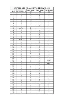
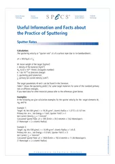
/
In this paper we discuss the development of sputter-Si technology for In this paper we discuss the development of sputter-Si technology for

In this paper we discuss the development of sputter-Si technology for - PDF document

natalia-silvester
natalia-silvester . @natalia-silvester
Follow
463 views
Uploaded On 2015-10-30

In this paper we discuss the development of sputter-Si technology for - PPT Presentation

2 Display Development Center Display Technology Development Group Sharp Corporation1 1 Polysilicon technology requires precursor Si material with very low Hcontent unlike aSi technologywhere ID: 177671

Display Development Center

Share:

Link:

Embed:

Download Presentation from below link

Download Pdf The PPT/PDF document "In this paper we discuss the development..." is the property of its rightful owner. Permission is granted to download and print the materials on this web site for personal, non-commercial use only, and to display it on your personal computer provided you do not modify the materials and that you retain all copyright notices contained in the materials. By downloading content from our website, you accept the terms of this agreement.


Presentation Transcript

In this paper we discuss the development of sputter-Si technology for application in the area of poly-Si TFTLiquid Crystal Displays. We present the motivation behind this development and the state-of-the-art inmaterials and devices, based on PVD-Si precursor material. The Si-sputtering process is analyzed and dataare presented on the quality of as-sputtered and post-annealed Si-films. The current drawbacks of Sisputtering are discussed, especially with respect to particles, film contamination and equipment availability.Based on the available data, strategies are presented to overcome these problems. PVD-Si technology hascome a long way and has become a viable candidate as a Si-deposition method for next generation of poly-Sibased applications. This technique is expected to play an even more important role, as the p-Si TFT-LCDindustry moves to ultra-low temperature processing and, in parallel, the need increases for process costIntroductionPhysical Vapor Deposition, or sputtering, is a deposition technique that is widely used in the thin filmindustry. A good treatise on sputtering can be found elsewhere. PVD relies on the bombardment of a target,made of the material to be deposited, primarily by energetic ions, which are generated by the ionization of aworking gas under an applied voltage. The target, upon bombardment, ejects atoms of the target material,which then float and condense on a substrate that is placed opposite to the target.Unlike other deposition methods, sputtering does not involve chemical interaction among the species. Eventhe so-called "reactive" sputtering follows the same deposition principle described above. The bombardmentof the target with energetic ions ejects equally energetic atoms, which eventually condense and deposit theirenergy on the film formed on the substrate. This source of energy can compensate traditional energy sources,such as heating, that are required to promote film growth and improve film characteristics. Hence, sputteringcan be used to deposit good quality films at moderate (¡)ery low temperatures (¡)vendown to room temperature. This enables compatibility with a wide variety of substrates and makesIntrinsically, Si sputter deposition offers 4 advantages: (a) elimination of toxic/hazardous process gases, (b)incorporated in the deposited film, (d)ability to pre-dope the Si film. These advantages translate to potential benefits in equipment andmaintenance cost, improved factory/worker safety and, quite importantly, process reduction byelimination/grouping of several process steps in one. Even though a-Si TFT-LCD technology is notparticularly drawn to Si sputtering, p-Si TFT-LCD technology seems to have more to gain by adopting thistechnology. We believe that this due to a combination of reasons, such as:Sputtering Technology of Si Films for Low-Temperature Poly-Si TFTsTolis VoutsasHirohiko NishikiMike AtkinsonYukihiko Nakata *2 Display Development Center, Display Technology Development Group, Sharp Corporation-1- 1. Polysilicon technology requires precursor Si material with very low H-content, unlike a-Si technologywhere the opposite is sought. This makes sputtering ideal technology, as the Hcontent is extremely low()ver, controllable2. Sputtering is one of the few techniques that can deposit good quality Si-films at temperatures as low asroom temperature. This is important for future applications requiring films to be deposited on heat-sensitive4. Sputtering from doped targets allows for deposition of lightly doped Si films. In this manner, the Vth-adjustment doping step can be merged with the deposition step to reduce processing steps and total cost. 5. Poly-Si flow typically requires more process steps than a-Si flow. Hence, process reduction is moreimportant, for cost control, to poly-Si process flow.6. Poly-Si process has not reached the level of maturity of a-Si process. The process flow is still open to newThese gains should be compared and contrasted to the potential issues/drawbacks associated with Sisputtering. These are active areas of research and solutions to these issues are key to the implementation ofsputtering to poly-Si TFT-LCD technology. We recognize four such areas:1. Particle reduction and control during Si sputtering.2. Simultaneous optimization of film quality, process throughput and device performance. 3. Development of sputtering technology is necessary not only for Si precursor but also for relevantdielectric films (i.e. SiO4. Development of Si-precursor/dielectric film sputtering equipment for mass production.In this paper we describe the state-of-the-art developments in sputtered Si-precursor technology forapplication in p-Si AM-LCDs. Film characteristics are shown and the corresponding electrical performanceof fabricated p-Si TFTs is presented. Equipment issues are discussed from the points of view of sputteringpractices and particle control. Guiding principles for equipment design are then presented. Finally, we1. PVD-Si FILM CHARACTERISTICS1.1 As-sputtered Si filmsFig. 1shows deposition rate data for DC sputtered Sifilms. The deposition rate scales linearly with the powerwith a coefficient of 2.8/kW-s. It should be noted thatvery high DC-power is not necessarily desirable, as highreadily obtained in the range of 4-6kW. These depositionrates are sufficient for high throughput and arecomparable with rates currently afforded by the PECVDmethod (~10/sec). However, there are also otherconsiderations for the selection of power level, includingparticle generation (discussed later) and overall filmquality. DC power supply set-point (P, kW) Fig.1 PVD-Si Dep. Rate-vs.-Power. The process pressure also affects the sputtered Si-filmincreases. However, even most importantly, sputterpressure is the main parameter controlling the degree ofincorporation of sputtering gas in the deposited filmFig. 2shows relevant data for the case of Si sputtering in. As expected, Ar incorporation decreases withincreasing pressure. This is attributed to the increasedgas-phase collision between energetic Ar ions and neutralSi atoms in the plasma region between target andFig. 2incorporation increases as the working gas ions areaccelerated at higher voltage. films is via collision of sufficient kinetic energy ions orneutrals with the growing film. Such energeticwith the Si-target. We have conducted simulations of thebackscattered atom energy distribution using TRIMTMsoftware. In this case, the incoming sputtering-ion energywas specified and the number and energy ofbackscattered atoms was recorded via the simulationsoftware. With this information, the energy distributionand the average energy of the backscattered atoms wasenergy of the ions directed towards the Si target. Once theenergy distribution of the backscattered ions/neutrals isknown one can use it to estimate the amount of energythat these energetic species deposit on the surface of thesputtered film. This energy can then be compared to theenergy required to affect microstructural changes in thedeposited Si-film (i.e. to 3.5-4.7eV, which is the estimatedSi-Si bond strength). As shown in Fig. 3atoms could affect microstructural changes in as-sputtered Si films, as they possess sufficient momentumthe deposited film. This points to the importantconclusion that the energetic Ar atoms are not onlyresponsible for undesirable Ar incorporation in the filmbut also for desirable modifications in the microstructureof the as-sputtered Si films. Substituting Ar with a lighterproblem, can adversely affect the quality of the sputteredSi film. This is implied by the results in Fig. 4clearly shown that He atoms do not possess enough Ar Pressure (mTorr)In-film Ar Concentration (at%) Fig.2 In-film Ar content as a function of Neutral Atom Energy (eV)Deposited Energy per Monolayer (eV/ion) energy and energy deposited on sputtered film. Neutral Atom Energy (eV)Deposited Energy per Monolayer (eV/ion) Fig. 4 Relationship between reflected He atom energyand energy deposited on sputtered film. energy to densify or otherwise modify the microstructureof the sputtered Si-film. With this information, we can conclude that as the Arpressure increases (to reduce the Ar content) another wayneeds to be provided to preserve the "quality" of the film.This could be accomplished by increasing the depositionpower to appropriate levels, guided by the principleFig. 3. Such improvement is indicated in Fig., which plots the refractive index of as-sputtered Si filmsas a function of the pressure and DC-power. Therefractive index is a measure of the density of the film,hence, in extension, the quality of the film. As the Ar-pressure increases, the refractive index decreases andhigher power is required to restore it to its original value.�Notice that at high pressures (5mTorr), not even 10kWis sufficient to restore the n-index.The quality of the film is also governed by the substrate temperature. Temperature does not impact thedeposition rate. However, it has strong impact on the microstructure according to the postulates of the1.2 Post-Annealed PVD-Si filmsSputtered-Si films are quite difficult to crystallize bymeans of solid-phase-crystallization. Typically, highcomplete phase transformation. This is primarilyattributed to sputtering gas incorporation in the film, aswell as to the high degree of structural disorder in the a-Sinetwork due to deposition at low temperatures and with. As a result, laser-annealing technique is moreappropriate for the crystallization of PVD-Si films. In thismanner, it is possible to take advantage of the higherabsorption coefficient of PVD-Si films to reduce the laserenergy density that is required to sufficiently melt the thinfilms. In the past, both continuous lasers (i.e. CW-Ar) andpulsed lasers (i.e. excimers, such as XeCl and KrF) haveFig. 6shows the crystalline characteristics of post-ELA sputtered-Si films as measured by Ramanspectroscopy. The FWHM of the Raman peak is reported and shown to decrease as the DC power and/or thedeposition temperature increase. Narrower peak (smaller FWHM) corresponds to better crystalline qualityafter laser annealing, correlates with the initial microstructure of the as-sputtered Si film. PVD-Si filmsdeposited at low temperature and/or low power tend to develop higher density of voids. This most likelyaffects the characteristics of the polysilicon film despite of the melt/recrystallization process that the film Ar Pressure (mTorr)Refractive Index, n (632nm) Fig. 5 Refractive index of sputtered Si-films as a function of Ar-pressure and DC-power. DC Power (kW)Raman Peak FWHM (cm Fig. 6 Raman FWHM of post-ELA sputtered-Si films versus DC-power and substrate temperature. undergoes when subjected to laser-annealing process. 1.3 Particle Generation and ControlParticle generation is one important issue that plaguesin the chamber is another source of particle formation.The probability of arcing in DC-mode significantlyincreases, as the target material becomes more resistive(as in the case of lightly doped Si). Particles can also begenerated due to film peeling off from the varioussurfaces, within the chamber, exposed to plasma. In thecase of sputtering over large areas, tiled Si targets areparticles. These are particles formed at the edges of Si-tiles due to stresses developing over the life of the targetfrom the tile cutting and edge-finishing process.We have conducted a number of particle tests simulatingdeposition of approximately one weekÕs mass productionprocessing. This corresponds to ~4,000 Si-films, or (at500 each) to ~200 µm of total film deposition. In thisstudy we used a horizontal type cluster tool. Weinvestigated the particle counts at given intervalsthroughout the test. In addition, we investigated particlecounts as a function of applied power to the Si-target.Fig. 71µm), which, although remain steady over long deposition periods, are above the desirable level. Moreover,these particles multiply as the DC-power increases. At DC-power levels necessary to maintain thethroughput, the particle levels are currently unacceptable. Switching to p-Si target material is not helpful asfar as small particles and, moreover, tends to enhance formation of large particles. Hence, the principlesolution to the intrinsic Si-particle formation is the utilization of vertical deposition chamber architecture.Development of such equipment is currently in progress for Si sputtering. Additionally, equipment makersproblem using their experience with relevant thin film coatings (SiNThe total results obtained from material characteristics, particle performance, film contamination, anodedesign, target considerations and general system maintenance lead to a number of basic system requirements1. The Si-target needs to be small, consisting of as few tiles as possible. This approach lowers the materialand fabrication costs and improves ease of replacement/maintenance. Continuous sputtering of the target is Deposited Si Thickness ( m) Particle Counts on 360x465mm Fig. 7 Particle data from a c-Si target obtained DC Power (kW)Particle # on 360x465 panel Fig. 8 Particle counts from a c-Si target as a function of applied DC-power. preferred to avoid surface oxidation and prevent microarcing. 2. Uniform gas flow is required to alleviate plasma and film non-uniformity, especially for reactive3. Vertical chamber configuration is necessary for Si-particle reduction and control.4. Improved anode designs are needed to alleviate the problem of the disappearing anode, common insputter-deposition of resistive materials. Alternative designs (such as dual cathode, or similar concepts) maybe necessary to completely eliminate this problem. Elimination of the metal anode can also resolve the metal5. Tool design should be compatible with high frequency pulsed DC power supply. Pulsed-DC mode iscommonly used in deposition of insulating films, as an alternative to RF sputtering.2. PVD-Si TFT CHARACTERISTICSIn this section we present the characteristics of poly-SiTFTs made with laser-crystallized PVD-Si precursor.Very good TFT results have been obtained using variousTFT fabrication flows and a wide process temperaturerange. Good data consistency was observed, after aninitial optimization period. The average mobility over acorresponding threshold voltage is in the range of 2.5V.[2,6,10,11]. The current level of interest in the industryand the general data agreement, we believe are goodindicators of the bright future of PVD-Si technology.We also fabricated pMOS p-Si TFTs and theFig. 9/Vs. The threshold voltage is centered on -2 to -3V.This value is in excellent agreement with that of nMOS Threshold Voltage (V) fabricated with PVD-Si precursor (45-nm thick films, deposited at 400¡C). Ar Pressure (mTorr)Ar Pressure (mTorr) Fig. 10 Characteristics of p-Si TFTs as a function of sputter pressure and DC-power. devices, also shown in Fig. 9. This means that good Vth-matching can be achieved by the PVD-Si precursorfor CMOS process flow. Fig. 10shows p-Si TFT characteristics as a function of the process conditions used for the deposition of thePVD-Si precursor film. The TFT performance improves at lower sputtering pressure, but it seems that anoptimum pressure setting exists, which depends upon the substrate temperature. This optimum is foundaround 2.5-4mTorr at 400¡C and drops even lower at 100¡C. The existence of this optimum, most likelyrelates to the microstructure of the as-sputtered film and its dependency on the process parameters shown inFig. 10In this paper we have reviewed Si-sputtering technology for application in p-Si TFT-LCDs. Sputtering canbe used to deposit a-Si films, which are subsequently crystallized, most commonly, by application ofexcimer-laser annealing. We reviewed the characteristics of PVD a-Si films and identified operatingconditions that yield high quality films. Sputtering can deposit Si-films at temperatures as low as RT, whichmakes this technology advantageous for application to temperature sensitive substrates, such as plastics. It is clear now that by optimization of the as-sputtered material and the crystallization process, high qualityp-Si films can be obtained. Poly-Si TFTs fabricated with this material show promising characteristics even atvery low fabrication temperatures. The TFT flow, however, needs to be considered in the optimizationprocess. Other steps, such as gate dielectric deposition, doping, activation and hydrogenation have also to beoptimized for the PVD-Si precursor.One of the issues of sputtering technology is particle generation and one way to overcome it is the use of RFtechnology. However, RF sputtering tends to yield low deposition rates, which are not compatible with massproduction requirements. Furthermore, RF technology is more complex and more expensive than DCtechnology. Smart equipment design is also necessary to overcome the problems of disappearing anode,metal contamination and particles. Most importantly, currently there is no mass production equipmentcommercially available for Si-sputtering. Hence, a number of challenges remain before PVD can become amainstream technology for Si and Si-dielectric film deposition. As the LCD industry moves to poly-Si technology, more consideration will be given to the advantagesoffered by PVD technology. Looking further ahead, film processing on transparent flexible substrates is verydifficult to achieve by current technology due to the severe temperature limitation of cheap plastics. Hence,sputtering seems to be one of the few viable technologies that can help close this gap.AcknowledgmentsThe authors would like to thank the members of SHARPÕs Tenri LCD Laboratories for their technicalReferences1) B. Chapman, 1980, "Glow Discharge Processes", J. Wiley, New York.2) G.A. Davis, R.E. Weiss, V. Aebi, R.T. Fulks, J. Ho and J.B. Boyce, 1999, ISSP'99 Proceedings, 234.3) N.D. Young, D.J. McCulloch, R.M. Bunn, I.D. French and I.G. Gale, 1998, Asia Display'98 Workshop4) H.F. Winters and E. Kay, 1967, J. Appl. Phys., 38, 3928. 5) A. Okamoto and T. Serikawa, 1987, J. Electrochem. Soc., 134, 1479.6) D.P. Gosain and S. Usui, 1998, The Electrochem. Soc. Symp. Proc., 98-22, 174.7) J.A. Thornton, J. Vac. Sci. Technol., 1974, 11, 666. 8) A.T. Voutsas and M.K. Hatalis, 1993, J. Electrochem. Soc., 140, 871.9) T. Serikawa, S. Shirai, A. Okamoto and S. Suyama, 1989, IEEE Trans. Electron Dev., 36, 1929.10) G.K. Giust and T.W. Sigmon, 2000, IEEE Trans. Electron Dev., 47, 207.11) P.G. Carey, P.M. Smith, P. Wickbold, M.O. Thompson and T.W. Sigmon, 1997, SID Symposium Digest,(received May 24, 2001)