/
K.Umadevi, P.Vishnu, B.Kailasam / International Journal of Engineering K.Umadevi, P.Vishnu, B.Kailasam / International Journal of Engineering

K.Umadevi, P.Vishnu, B.Kailasam / International Journal of Engineering - PDF document

pamella-moone
pamella-moone . @pamella-moone
Follow
382 views
Uploaded On 2016-05-21

K.Umadevi, P.Vishnu, B.Kailasam / International Journal of Engineering - PPT Presentation

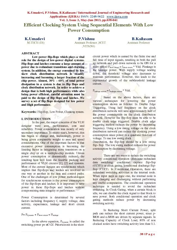
Applications IJERA IS SN 2248 9622 wwwijeracom Vol 3 Issue 3 May Jun 2013 pp 0 38 041 38 Page Efficient Clocking System Using Sequential Elements With Low Power Consumption KUma ID: 328303

Applications (IJERA) IS SN: 2248 - 9622 www.ijera.com Vol.

Share:

Link:

Embed:

Download Presentation from below link

Download Pdf The PPT/PDF document "K.Umadevi, P.Vishnu, B.Kailasam / Intern..." is the property of its rightful owner. Permission is granted to download and print the materials on this web site for personal, non-commercial use only, and to display it on your personal computer provided you do not modify the materials and that you retain all copyright notices contained in the materials. By downloading content from our website, you accept the terms of this agreement.


Presentation Transcript

K.Umadevi, P.Vishnu, B.Kailasam / International Journal of Engineering Research and Applications (IJERA) IS SN: 2248 - 9622 www.ijera.com Vol. 3, Issue 3, May - Jun 2013, pp. 0 38 - 041 38 | Page Efficient Clocking System Using Sequential Elements With Low Power Consumption K.Umadevi P.Vishnu B.Kailasam M.TECH (ES) Assistant Professor ,SCET Assistant Professor ,VITS(N6) ABSTRACT Low power flip - flops which plays a vital rol e for the design of low - power digital systems . Flip flops and latches consume a large amount of power due to redundant transitions and clocking system. In addition, the energy consumed by low skew clock distribution network is steadily increasing and becom ing a larger fraction of the chip power. Almost, 30% - 60% of total power dissipation in a system is due to flip flops and clock distribution network. In order to achieve a design that is both high performances while also being power efficient, careful att ention must be paid to the design of flip flops and latches. We survey a set of flip flops designed for low power and High performance. K ey w o r d s : F l i p - f l o p , L ow P o w er , Clocking system. I. INTRODUCTION In the past, the major concerns of the VLSI designer were area, performance, cost and reliability. Power consideration was mostly of only secondary importance. In recent years, however, this has begun to change and, increasingly, power is being given comparable weight to area and speed considerations. One of the important factors is that excessive power consumption is becoming the limiting factor in integrating more transistors on a single chip or on a multiple - chip module. Unless power consumption is dramatically reduced, the resulting heat will limit the fe asible packing and performance of VLSI circuits [1] , [ 2 ] and systems. Most of the current designs are synchronous which implies that flip - flops and latches are involved in one way or another in the data and control paths. One of the challenges of low power methodologies for synchronous systems is the power consumption of the flip - flops and latches. It is important to save power in these flip - flops and latches witho ut compromising state integrity or performance. Power Consumption is determined by several f actors including frequency f, supply voltage, data activity, capacitance, leakage and short circuit current. P= P dynamic + P short circuit + P leakage In the above equation, P dynamic is cal led the switching power p= α Cv2f. Pshortcircuit is the short circ uit power which is caused by the finite rise and fall time of input signals, resulting in both the pull up network and pull down network to be ON for a short period P short circuit = I short circuit * Vdd. Pleakage is the leakage power. With supply voltage s caling down, the threshold voltage also decreases to maintain performance. However, this leads to the exponential growth of th e subthreshold leakage current. P leakage current = I leakage current * Vdd. Based on the above factors, there are various techni ques for lowering the power consumption shown as follows: In Double Edge Triggering, Using half frequency on the clock distribution network will save approximately half of the power consumption on the clock distribution network. However the flip - flop must be able to be double clock edge triggered. Double clock edge triggering method reduces the power by decreasing frequency. Using a low swing voltage on the clock distribution network can reduce the clocking power consumption since power is a quadratic funct ion of voltage. To use low swing clock Distribution, the flip - flop should be a low swing flip - flop. The low swing method reduces the power consumption by decreasing voltage. There are two ways to reduce the switching activity: conditional operation (elim inate redundant data switching: conditional capture flip - flop (CCFF)) or clock gating, conditional discharge flip - flop (CDFF). In Conditional Operation, there are redundant switching activities in the internal node. When input stays at logic one, the inter nal node is kept charging and discharging without performing any useful computation. The conditional operation technique is needed to av oid the redundant switching. In Clock Gating, when a certain block is idle, we can disable the clock signal to that bloc k to save power. Both conditional operation and clock gating methods reduce power by decreasing switching activity . In Reducing Short Current Power, split path can reduce the short current power, since p - MOS and n - MOS are driven by separate signals. In R educing Capacity of Clock Load, 80% of non clocked nodes have switching activity less than 0.1. K.Umadevi, P.Vishnu, B.Kailasam / International Journal of Engineering Research and Applications (IJERA) IS SN: 2248 - 9622 www.ijera.com Vol. 3, Issue 3, May - Jun 2013, pp. 0 38 - 041 39 | Page This means reducing power of clocked nodes is important since clocked node has 100% activity. One effective way of low power design for clocking system is to re duce clock capacity load by minimizing number of clocked transistor. Any local clock load reduction will also decrease the global power consumption. This method reduces power by decreasing clock capacity. II. SURVEYED TECHNIQUE FOR REDUCING CLOCK CAPACITY Most of the flip - flops presented here are dynamic in nature, and some internal nodes are precharged and evaluated in each cycle without producing any useful activity at the output when the input is stable. Reducing this redundant switching activity has a profound effect in reducing the power dissipation, and in the literature many techniques were presented for this purpose . A brief survey of such techniques is conducted in this work, and the main techniques were classified as follows: 2.1 Conditional Cap ture Flip Flop Conditional Capture technique is proposed for disabling redundant internal transitions. This technique achieves significant power reduction at little or no delay penalties. Motivation behind Conditional Capture technique [3] is the observatio n that considerable portion of power is consumed for driving internal nodes even when the value of the output is not changed (corresponding to low input activities). It is possible to disable internal transitions when it is detected that they will have no effect on output. But the drawback is increased set - up time for sampling zero (low level) and also heavier load is presented to the Q output of the flip flop. 2 . 2 Conditional Precharge Flip Flop For overcoming the disadvantage in Conditional Capture Flip Flop [3] , Conditional pre - charge flip flop is proposed One of the most important contributions of this work is related to preventing unconditional pre - charge operation of the internal node, tightly connected to excessive power dissipation of the circuit. Th is is accomplished by controlling the return of internal node to inactive (high) state, allowing the internal node to stay at low level until input condition is changed. This approach efficiently eliminates the unnecessary transitions of the internal node as well as race condition at the output. There are two main disadvantages: One is introducing another critical path for low input level capture. Another drawback is increasing the output load due to the feedback, which although minimal size transistor can be used, being out of the critical path, can affect total propagation delay. 2 . 3 Conditional Discharge Flip Flop Conditional Discharge Flip - flop (CDFF) [4] not only reduces the internal switching activities, but also generates less glitches at the output, while maintaining the negative setup time and small Q - to - output delay characteristics. With a data - switching activity of 37.5%, this flip - flop can save up to 39% of the energy with the same speed. In this Flip - flop, the extra switching activity is eliminat ed by controlling the discharge path when the input is stable HIGH. In this scheme, an n - MOS Transistor is inserted in the discharge path with the high - switching activity. When the input undergoes a LOW - to - HIGH transition, the output changes from HIGH to L OW. This transition at the output switches off the discharge path of the first stage to prevent it from discharging or doing evaluation in succeeding cycles as long as the input is stable. But the disadvantage is it used 15 clocked transistors. 2 . 4 Condit ional Data Mapping Flip Flop Conditional Data Mapping Flip flop used only seven clocked transistors, resulting in about 50% reduction in th e number of clocked transistors, hence CDMFF [5] used less power than CCFF and CDFF as shown in fig 2. 1.Note that CDFF used double edge clocking. For simplicity purposes, we did not include the power savings by double edge triggering on the clock distribution network. This shows the effectiveness of reducing clocked transistor numbers to achieve low power, Since CDMFF out performs CCFF and CDFF. But it makes very difficult to apply the Double edge triggering and also it cannot be used in a low swing environment. Moreover it reduces the number of clocked transistors but it has redundant clocking as well as floating node. So we can move into the clocked pair shared flip - flop. FIGURE 2.1 :CDMFF. K.Umadevi, P.Vishnu, B.Kailasam / International Journal of Engineering Research and Applications (IJERA) IS SN: 2248 - 9622 www.ijera.com Vol. 3, Issue 3, May - Jun 2013, pp. 0 38 - 041 40 | Page 2 . 5 CLOCKED PAIR SHARED FLIP FLOP (CPSFF) Clocked Pair Shared flip - flop (CPSFF)[6 ] to use less clocked transistor than CDMFF and to overcome the floating problem in CDMFF as shown in fig 2. 2. In the clocked - pair - shared flip - flop, clocked pair is shared by first and second stage. An always on p - MOS, P1, is used to charge the internal node rather than using the two clocked pre charging transistors (P1,P2) in CDMFF. Comparing with CDM FF, a total of three clocked transistors are reduced, such that the clock load seen by the clock driver is decreased, resulting in an efficient design. CPSFF uses four clocked transistors rather than seven clocked transistors in CDMFF, resulting in approxi mately 40% reduction in number of clocked transistors. Figure 2 .2 : Clocked Pair Shared Flip Flop III . Proposed Low Power Clocked Pass Transistor Flip - Flop Design By using the Pass Transistor Logic family idea we are designing this circuit as well as b y using the pass transistor logic we are using only one clocking transistor so it will be Consuming only less power in the clock network of the Flip flop when compared to all other circuits. As well as we are having only 6 Transistors excluding the not g ates also. So we will be having much reduced power and area when compared to the other two designs. At the same time due to the reduced no of transistor count we can reduce the delay oriented things also. Thus we are reducing the overall switching delay an d power, area consumption. So this circuit will be acting as good sequential elements when compared to other flip - flop design. The graph represents the input & output characteristics of our proposed system from that we can clearly understand how it works as negative edge triggered flip - flop. There is some nano seconds delay is there even though it’s a negligible amount only. Those delays can be further reduced by reducing the sizes of the transistor we are using in this circuit. Or by reducing the nano met er technology also we can reduce the constraints. The Layout design of the proposed new flip - flop is shown in the figure 3.2 the area of that is mentioned at the dow nside of the layout. Figure 3 .1 : Proposed Low Power Clocked Pass Transistor flip - floP Figure 3.2 : Layout of theLCPTFF Proposed Design Thus the Our Proposed Low Power Clocked Pass Transistor flip - flop (LCPTFF Fig.3 .1 ) design shows much less power & Area constraints than the Existing two Flip - Flop designs. As well as the Proposed design wi ll be having very less clock delay when compared to all other circuits. So it can be used in all the future sequential elements for high speed low SOC’c manufacturing. K.Umadevi, P.Vishnu, B.Kailasam / International Journal of Engineering Research and Applications (IJERA) IS SN: 2248 - 9622 www.ijera.com Vol. 3, Issue 3, May - Jun 2013, pp. 0 38 - 041 41 | Page III. Tabulation Power & Area Comparison Table using CMOS012 um FLIP FLOP No. of Transist or Power Consumpt ion Area Consumpti on Width CDMF F 7 11.380µW 278.1µm2 31.3µ m CPSFF 4 6.184µW 207.8µm2 22.2µ m LCPT FF 4 4.663 µW 138.1µm2 16.4µ m Thus the Our Proposed Low Power Clocked Pass Transistor flip - flop design shows much less power & Area constraints than the Existing two Flip - Flop designs. As well as the Proposed design will be having very less clock delay when compared to all other circuits. So it can be used in all the future sequential elements for high speed low SOC’c manufacturin g. IV . CONCLUSION In this paper, a variety of design techniques for low power clocking system are reviewed. One effective method, reducing capacity of the clock load by minimizing number of clocked transistor, is elaborated. Following the approach, one novel CPSFF is proposed, which reduces local clock transistor number by about 40%. In view of power consumption of clock driver, the new CPSFF outperforms prior arts in flip - flop design by about 24%. Furthermore, several low power techniques, including low swing and double edge clocking, can be explored to incorporate into the new flip - flop to build clocking systems. REFERENCES [1 ] C. L. Kim and S. Kang, “A low - swing clock double edge - triggered flip - flop,” IEEE J. Solid - State Circuits , vol. 37, no. 5, pp. 648 – 652, May 2002. [2 ] J. Rabaey, A. Chandrakasan, and B. Nikolic , Digital Integrated Circuits . Englewood Cliffs, NJ: Prentice - Hall, 2003. [3 ] B. Kong, S. Kim, and Y. Jun, “Conditional capture flip - flop for statistical power reduction,” IEEE J. Soli d - State Circuits , vol. 36, no. 8, pp.1263 – 1271, Aug. 2001. [4 ] P. Zhao, T. Darwish, and M. Bayoumi, “High - performance and lowpower conditional discharge flip - flop,” IEEE Trans. Very Large Scale Integr. (VLSI) Syst. , vol. 12, no. 5, pp. 477 – 484, May 2004. [5] C. K. Teh, M. Hamada, T. Fujita, H. Hara, N. Ikumi, and Y. Oowaki, “Conditional data mapping flip - flops for low - power and high - performance systems,” IEEE Trans. Very Large Scale Integr. (VLSI) Syst. ,vol. 14, no. 12, pp. 1379 – 1383, Dec. 2006. [6] Peiy i Zhao, Jason McNeely, WeidongKuang, Nan Wang, and“Design of Sequential Elements for Low PowerClocking System” IEEE Transaction May 2011