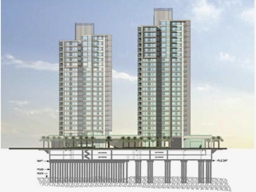
/
GRADUATION PROJECT Foundation System Design for Al Nimmer Commercial Building GRADUATION PROJECT Foundation System Design for Al Nimmer Commercial Building

GRADUATION PROJECT Foundation System Design for Al Nimmer Commercial Building - PowerPoint Presentation

samantha
samantha . @samantha
Follow
66 views
Uploaded On 2023-09-21

GRADUATION PROJECT Foundation System Design for Al Nimmer Commercial Building - PPT Presentation

Prepared by Noor SIssa Hala SQasem Heba AMassri Iman Abu Durrah To provide some background information about foundation systems To design piles foundation system for the proposed building ID: 1019086

foundation piles shear design piles foundation design shear load mat building reinforcement bearing capacity depth soil column cap wall

Share:

Link:

Embed:

Download Presentation from below link

Download Presentation The PPT/PDF document "GRADUATION PROJECT Foundation System Des..." is the property of its rightful owner. Permission is granted to download and print the materials on this web site for personal, non-commercial use only, and to display it on your personal computer provided you do not modify the materials and that you retain all copyright notices contained in the materials. By downloading content from our website, you accept the terms of this agreement.


Presentation Transcript

1.

2. GRADUATION PROJECTFoundation System Design for Al Nimmer Commercial Building Prepared by: Noor S.Issa Hala S.Qasem Heba A.Massri Iman Abu Durrah

3. To provide some background information about foundation systems.To design piles foundation system for the proposed building. To design Mat over Piles as an alternative foundation system.To make cost & duration estimation for both systems. Project Objectives

4. Building DescriptionThe plan area = 405m ². Number of floors =13 floors such that: Two basement floors (3.5 m height). One ground floor and ten replicated stories (3 m). Located at the city center of Nablus.

5. Introduction The main purpose of foundation is to receive structural loads and external loads applied to the structure and transmit them in to the soil at a given depth below the ground safely (without causing soil failure or unsafe differential settlement of the supported structure).

6. General Requirements of FoundationsDepth must be adequate and below the zone of seasonal volume changes. System must be safe against overturning, rotation, sliding, and soil rupture. The foundation should be economical.

7. Review of Foundation TypesShallow Foundations:Isolated (Spread) Foundations.Combined Foundation.Continuous(Wall) Foundation.Strip Foundation.Mat Foundation.

8. Review of Foundation TypesDeep Foundations:Piles.piers. Caissons.

9. Piles piles are long members that transfer the load to deeper soil or rock of high bearing capacity avoiding shallow soil of low bearing capacity, and they can be precast or cast in situ.

10. Piles Classification of piles with respect to load transmission:End bearing piles.Skin friction piles (cohesion piles). Combination of friction and end bearing piles.

11. Structural Analysis A structural analysis has been done for the proposed building using the software program SAP in order to determine the superstructure loads acting on the foundation level, and the readings were very close to the manual measurements when comparing them.

12. Sap Model for The Building

13. Results of Structural AnalysisAllowable loads of columns at the foundation level.

14. Results of Structural AnalysisLoad of building :Manually: building load =101118.5 KN. From SAP: building load =99171.87 KN.Error = 1.96% < 5%.

15. Subsurface Exploration Three boreholes were dug out, one is 20 m depth and two are 12 m depth according to the standards, from these boreholes the main soil type is sedimentary dark brownish silty clay of high plasticity with pebbles.Lab tests has been conducted on soil samples from the boreholes at different depths, these tests included moisture content, atterberg limits, and undrained cohesion.

16. RecommendationsPiles Foundation is recommended for this site.Excavation support system should be constructed for this project (about 8 m below the existing ground surface).

17. Piles Foundation DesignTypes and Capacity of Piles: AllPiles program was used to determine the allowable bearing capacity for some common types of piles each has a specific diameter and length.

18. The Allowable Bearing Capacity of Piles From AllPiles

19. The Allowable Bearing Capacity of Piles From AllPiles

20. Types of Piles UsedThe two main types of piles that found to be the most suitable to be used for this loading system are mentioned in the table below.

21. Foundation DesignFoundation design includes:Design of piles and caps under columns.Design of piles and caps under shear walls.Design of tie beams between pile’s caps.

22. Critical ColumnsColumns were divided into groups, each has a representative column (the critical one) as in the following table.

23. Design CalculationsFor every critical column the calculations are:Number of piles needed under column.Cap dimensions and piles distribution.Depth of cap (according to one way shear). Checking punching for both column and piles.Steel reinforcement for both piles and piles cap.

24. Design TheoriesNo. of piles under column= Minimum center to center spacing =2.5diam between adjacent piles.20 cm minimum clear distance between the edges of cap and pile, that acts as a cover for the pile.

25. Design TheoriesDepth of cap according to one way shear: Vu.pile = ФVc =Punching check: If Bc ≤ 2;If Bc > 2;

26.

27. Design Theories Main Reinforcement: As =ρ b d. Minimum Reinforcement: Asmin= .0018 bh.

28.

29. Piles Reinforcement (Theory)Vertical Reinforcement:Pile capacity =ФPn >Vu.pile As.pile = 0.5% Ag. ФPn = 0.7x0.85x [(0.85xƒc x (Ag – As) + (As fy)].Spiral Reinforcement: Assume bars diameter (12 mm).Find spacing between spirals from the equation:

30. Piles Reinforcement

31. Design of Shear WallsNo. of piles under shear wall=Shear wall No.1 8 piles. Shear wall No.2 3 piles.Minimum center to center spacing = 2.5diam.

32. Design of Shear WallsPiles reactions are at the center of shear wall so: Effective depth of cap “d” =30 cm (minimum),and total depth “h”= 45 cm.As =A shrinkage=.0018bh (zero moment).Longitudinal Reinforcement 5Ф18.Lateral Reinforcement 4Ф18\m.

33. Plan View of Shear Wall

34. Design of Tie BeamsAssume b=50 cm (for all tie beams).Maximum load of tie beam "Q"=10 % of the maximum load of columns Q=66.19 ton.ρ = .8 %. As= = ρbd As = 30.086 cm², so use 10 ɸ 25.d = 75 cm, so h= 80 cm.

35. Plan View of Piles' Caps & Tie Beams

36. MAT OVER PILES qu.mat = Qmat = mat load= qall.mat xAmat. =156.4 x 405 = 63342.6 KN. Piles load= building load - mat load. = 99171.88 – 63342.63= 35829.28 KN.

37. MAT OVER PILESPiles used for mat are 80 cm diameter and 16 m length.Number of piles= = 44 piles. Depth of mat “d” = 100 cm such that for the most critical column (No.8) no punching occurs:Φ Vc = 4555 KN > Vu.max = 4326.65 KN (from SAP).

38. Maximum Shear Force From SAP

39. Cost and Duration Estimation

40. THANK YOU