/
ECE 477 Design Review Team ECE 477 Design Review Team

ECE 477 Design Review Team - PowerPoint Presentation

tatyana-admore
tatyana-admore . @tatyana-admore
Follow
348 views
Uploaded On 2018-10-14

ECE 477 Design Review Team - PPT Presentation

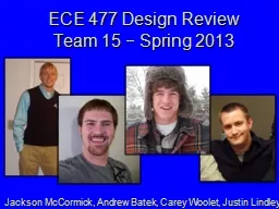
15 Spring 2013 Jackson McCormick Andrew Batek Carey Woolet Justin Lindley Presentation Outline Project overview Projectspecific success criteria Block diagram Component selection rationale ID: 690036

schematic control layout pcb control schematic pcb layout design project drsstc hfsstc coil ability input pwm power supply adc

Share:

Link:

Embed:

Download Presentation from below link

Download Presentation The PPT/PDF document "ECE 477 Design Review Team" is the property of its rightful owner. Permission is granted to download and print the materials on this web site for personal, non-commercial use only, and to display it on your personal computer provided you do not modify the materials and that you retain all copyright notices contained in the materials. By downloading content from our website, you accept the terms of this agreement.


Presentation Transcript

Slide1

ECE 477 Design Review Team

15

 Spring 2013

Jackson McCormick, Andrew

Batek

, Carey

Woolet

, Justin LindleySlide2

Presentation Outline

Project overview Project-specific success criteriaBlock diagram

Component selection rationalePackaging designSchematic and theory of operation

PCB layoutSoftware design/development status

Project completion timelineQuestions / discussionSlide3

Project Overview - Abstract

Interweaving the impressive visual power of electricity and the visceral emotion of music, Acoustic Storm takes analog or digital audio input and outputs its own rendition using two varieties of solid state tesla coils. Slide4

Overview – Selected Design DetailsInput OptionsMidiAnalog

Multiple Coil typesClass E HFSSTC (Tweeters)DRSSTC (Mids)Control Options

Temperature and spectrogram outputPotential for volume and tone controlSlide5

Project-Specific Success Criteria

An ability to decode MIDI input and output a PWM signal at the corresponding frequenciesAn ability to receive analog input, digitize it using an ADC, and output a PWM signal corresponding to the analog waveform

An ability to monitor and control system status (i.e. volume control and temperature monitoring) through an LCD and input systemAn ability to generate and control a power output sufficient to drive an electrical arc based acoustic device

An ability to split audio signals at certain crossover frequencies and send them to a specific speaker (i.e. tweeters, mid, bass signals)Slide6

Block DiagramSlide7

Major Component Selection RationaledsPIC

Microcontroller16 Bit PWMDigital Signal LibraryWolfson ADC

24 Bit Delta Sigma, I2SVishay/ Siliconix MOSFET600 V OperationLow switching times

Low Rdson

High Current capabilitySlide8

Selection Rationale (cont.)Coil ParametersHFSSTC Secondary Inductance

DRSSTC Primary InductanceDRSSTC Secondary InductanceDRSSTC Primary tank capacitor

DRSSTC Secondary capacitanceSlide9

Packaging ConsiderationsSafety ConsiderationsPhysical Isolation – PlexiglasElectrical Isolation – Faraday Cage

Contact Close SwitchPower Circuitry located under coilsCoaxial Cable to carry PWM signalsGeneric control box casing with large distance between coils and control.Slide10

Coil PackagingHFSSTC12”x12”x20”

~13.486 lbs.~$90DRSSTC

20”x20”x24”~29.5 lbs.~$151*Plexiglas is already owned by Team #15 – Cost will be significantly less than shown*Slide11

Detailed Coil Packaging Design

Coil Packaging

AWB - 2/5/2013

Front/Side:

Top:

W/O Faraday Cage

W/ Faraday Cage

20”

20”

12”

12”

20”

24”

Plexiglas

Chain-link (or similar)

Scale:

=

1”

DRSSTC Box

HFSSTC BoxSlide12

Schematic/ Theory of OperationOverviewMicrocontroller5V/3.3V Supply

ADCUART translating LCD 12V Supply HFSSTC Control Slide13

Schematic/Theory of OperationSlide14

Schematic - MicroSlide15

Schematic – Power SupplySlide16

Schematic - ADCSlide17

Schematic - UARTSlide18

Schematic - MIDISlide19

Schematic - OutputsSlide20

SchematicSlide21

Schematic – 12V SupplySlide22

Schematic – HFSSTC ControlSlide23

PCB Layout ADC close to audio input

Multiple Voltage Levels Wide Traces

Separate Areas for each function Aesthetics Slide24

PCB LayoutSlide25

PCB Layout - MicroSlide26

PCB Layout - PowerSlide27

PCB Layout - InputsSlide28

PCB Layout - LCDSlide29

PCB Layout - OutputSlide30

PCB LayoutSlide31

Software Design/Development StatusCompleted

UART receive PWM control function SPI

Development State machine for midi to parse data Look up table for frequenciesBasic FFTs for SpectrumFIR filtering for PWM outputs Slide32

Project Completion Timeline

Week:

8

9

10

11

12

13

14

15

16

17

Obtain Workroom


Construction/ Design


- Power Supply


- HFSSTC


- DRSSTC


- Primary Capacitors


- Non- PCB Circuits


Programming


- MIDI


- ADC


- LCD


- Control


- Temp. Monitoring


Testing


Debugging


Design Tweaking/ Finishing


 Slide33

Questions / DiscussionSlide34

Questions / DiscussionSlide35

Questions / Discussion