PDF-Figure 1Figure 2
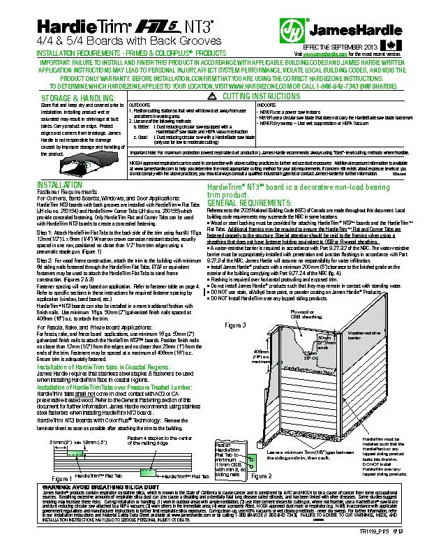
HardieTrim153 Corner TabsWeatherresistive
Leave a minimum 3mm18 gap between406mm16 ocmaximum HardieTrim153 Flat TabHardieTrim153 Flat Tab
HardieTrimFlat Tab to 25mm
Download Presentation
"Figure 1Figure 2" is the property of its rightful owner. Permission is granted to download and print materials on this website for personal, non-commercial use only, provided you retain all copyright notices. By downloading content from our website, you accept the terms of this agreement.
Presentation Transcript
Transcript not available.