Automotive RADAR Bitfields Verification to Support
Description: Automotive RADAR Bitfields Verification to Support Validation of Silicon Paulraj M K and Amol Dhok NXP Semiconductors, Bangalore India Accellera Systems Initiative 1 Introduction of Automotive Radar Automotive Radar sensors are a
Related Topics
Download Presentation
"Automotive RADAR Bitfields Verification to Support" is the property of its rightful owner. Permission is granted to download and print the materials on this website for personal, non-commercial use only, and to display it on your personal computer provided you do not modify the materials and that you retain all copyright notices contained in the materials. By downloading content from our website, you accept the terms of this agreement.
Presentation Transcript
slide1. Automotive RADAR Bitfields Verification to Support Validation of Silicon Paulraj M K and Amol Dhok
NXP Semiconductors, Bangalore India © Accellera Systems Initiative 1<br>
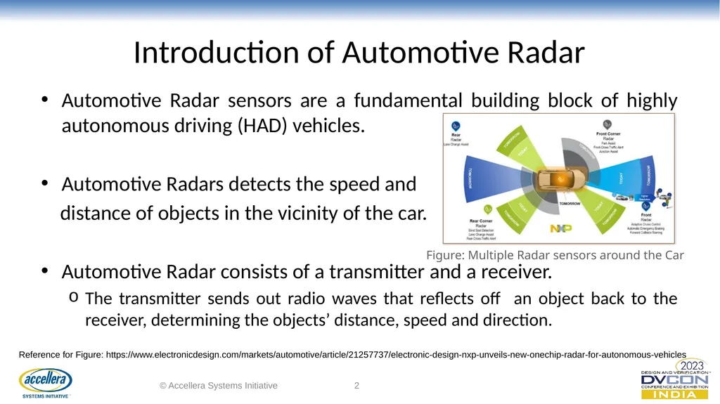
slide2. Introduction of Automotive Radar Automotive Radar sensors are a fundamental building block of highly autonomous driving (HAD) vehicles.
Automotive Radars detects the speed and
distance of objects in the vicinity of the car.
Automotive Radar consists of a transmitter and a receiver.
The transmitter sends out radio waves that reflects off an object back to the receiver, determining the objects’ distance, speed and direction. © Accellera Systems Initiative 2 Reference for Figure: https://www.electronicdesign.com/markets/automotive/article/21257737/electronic-design-nxp-unveils-new-onechip-radar-for-autonomous-vehicles Figure: Multiple Radar sensors around the Car<br>
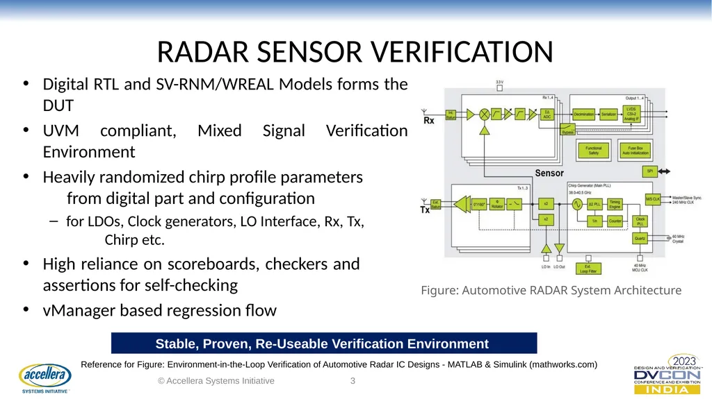
slide3. RADAR SENSOR VERIFICATION Digital RTL and SV-RNM/WREAL Models forms the DUT
UVM compliant, Mixed Signal Verification Environment
Heavily randomized chirp profile parameters from digital part and configuration
for LDOs, Clock generators, LO Interface, Rx, Tx, Chirp etc.
High reliance on scoreboards, checkers and assertions for self-checking
vManager based regression flow © Accellera Systems Initiative 3 Figure: Automotive RADAR System Architecture Stable, Proven, Re-Useable Verification Environment Reference for Figure: Environment-in-the-Loop Verification of Automotive Radar IC Designs - MATLAB & Simulink (mathworks.com)<br>
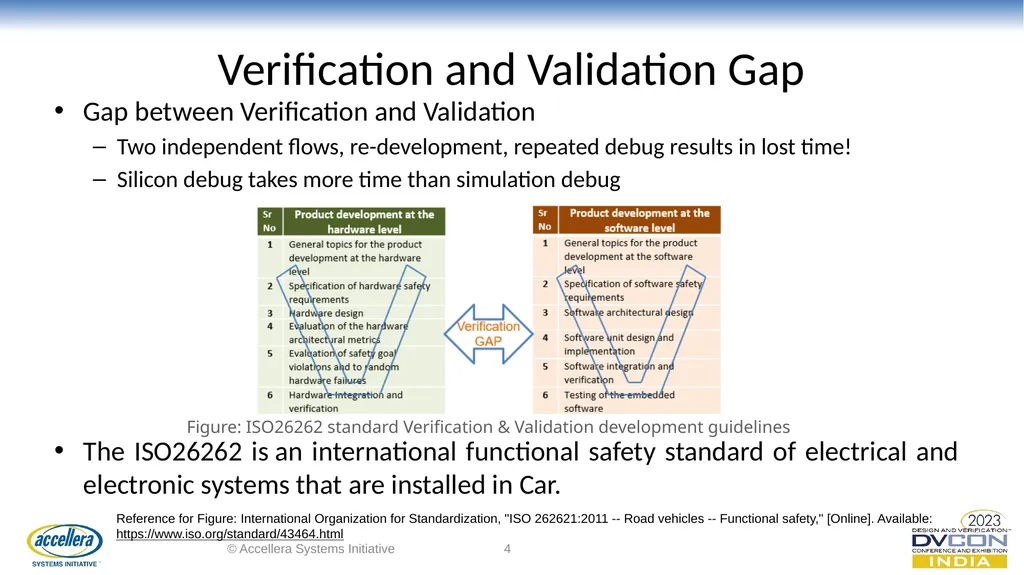
slide4. Verification and Validation Gap Gap between Verification and Validation
Two independent flows, re-development, repeated debug results in lost time!
Silicon debug takes more time than simulation debug
The ISO26262 is an international functional safety standard of electrical and electronic systems that are installed in Car. © Accellera Systems Initiative 4 Figure: ISO26262 standard Verification & Validation development guidelines Reference for Figure: International Organization for Standardization, "ISO 262621:2011 -- Road vehicles -- Functional safety," [Online]. Available: https://www.iso.org/standard/43464.html<br>
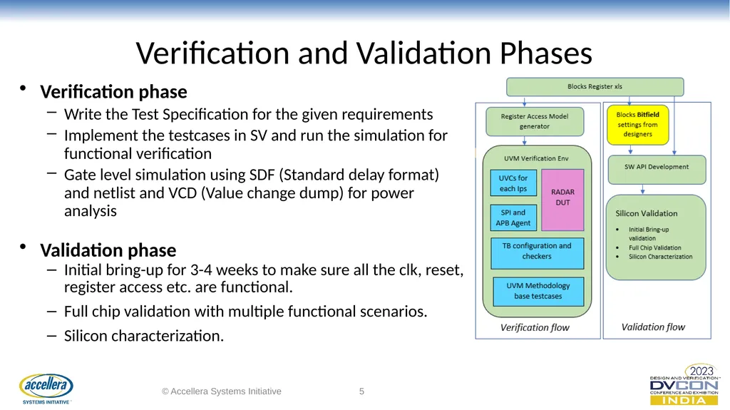
slide5. Verification and Validation Phases Verification phase
Write the Test Specification for the given requirements
Implement the testcases in SV and run the simulation for functional verification
Gate level simulation using SDF (Standard delay format) and netlist and VCD (Value change dump) for power analysis
Validation phase
Initial bring-up for 3-4 weeks to make sure all the clk, reset, register access etc. are functional.
Full chip validation with multiple functional scenarios.
Silicon characterization. © Accellera Systems Initiative 5<br>
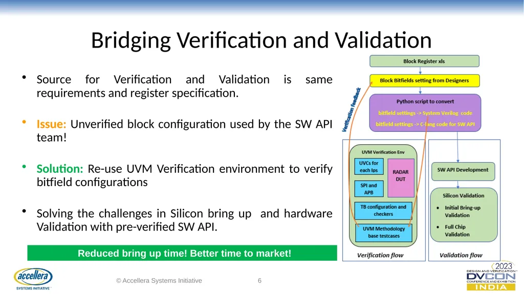
slide6. Bridging Verification and Validation Source for Verification and Validation is same requirements and register specification.
Issue: Unverified block configuration used by the SW API team!
Solution: Re-use UVM Verification environment to verify bitfield configurations
Solving the challenges in Silicon bring up and hardware Validation with pre-verified SW API. © Accellera Systems Initiative 6 Reduced bring up time! Better time to market!<br>
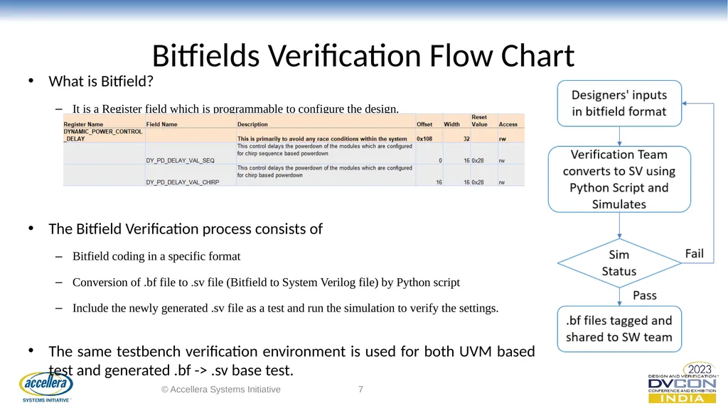
slide7. Bitfields Verification Flow Chart What is Bitfield?
It is a Register field which is programmable to configure the design.
The Bitfield Verification process consists of
Bitfield coding in a specific format
Conversion of .bf file to .sv file (Bitfield to System Verilog file) by Python script
Include the newly generated .sv file as a test and run the simulation to verify the settings.
The same testbench verification environment is used for both UVM based test and generated .bf -> .sv base test. © Accellera Systems Initiative 7<br>
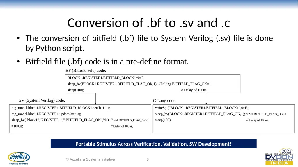
slide8. Conversion of .bf to .sv and .c The conversion of bitfield (.bf) file to System Verilog (.sv) file is done by Python script.
Bitfield file (.bf) code is in a pre-define format. © Accellera Systems Initiative 8 BLOCK1.REGISTER1.BITFIELD_BLOCK1=0xF;
sleep_bv(BLOCK1.REGISTER1.BITFIELD_FLAG_OK,1); //Polling BITFIELD_FLAG_OK=1
sleep(100); // Delay of 100us Portable Stimulus Across Verification, Validation, SW Development! writeSpi(“BLOCK1.REGISTER1.BITFIELD_BLOCK1”,0xF);
sleep_bv(BLOCK1.REGISTER1.BITFIELD_FLAG_OK,1); //Poll BITFIELD_FLAG_OK=1
sleep(100); // Delay of 100us; reg_model.block1.REGISTER1.BITFIELD_BLOCK1.set('b1111);
reg_model.block1.REGISTER1.update(status);
sleep_bv("block1","REGISTER1”," BITFIELD_FLAG_OK",'d1); // Poll BITFIELD_FLAG_OK=1
#100us; // Delay of 100us; SV (System Verilog) code: C-Lang code: BF (Bitfield File) code:<br>
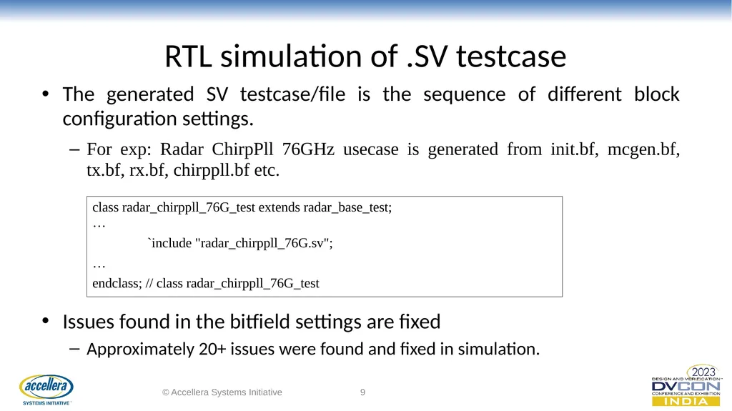
slide9. RTL simulation of .SV testcase The generated SV testcase/file is the sequence of different block configuration settings.
For exp: Radar ChirpPll 76GHz usecase is generated from init.bf, mcgen.bf, tx.bf, rx.bf, chirppll.bf etc.
Issues found in the bitfield settings are fixed
Approximately 20+ issues were found and fixed in simulation. © Accellera Systems Initiative 9 class radar_chirppll_76G_test extends radar_base_test;…
`include "radar_chirppll_76G.sv";
…
endclass; // class radar_chirppll_76G_test<br>
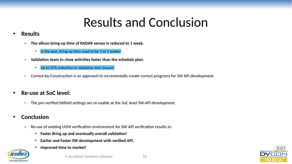
slide10. Results and Conclusion Results
The silicon bring-up time of RADAR sensor is reduced to 1 week.
In the past, bring-up time used to be 3 to 5 weeks!
Validation team to close activities faster than the schedule plan.
Up to 25% reduction in validation test closure!
Correct-by-Construction is an approach to incrementally create correct programs for SW API development.
Re-use at SoC level:
The pre-verified bitfield settings are re-usable at the SoC level SW-API development.

Conclusion
Re-use of existing UVM verification environment for SW API verification results in:
Faster Bring up and eventually overall validation!
Earlier and Faster SW development with verified API.
Improved time to market! © Accellera Systems Initiative 10<br>
slide11. Q&A Thank you © Accellera Systems Initiative 11<br>
NXP Semiconductors, Bangalore India © Accellera Systems Initiative 1<br>
slide2. Introduction of Automotive Radar Automotive Radar sensors are a fundamental building block of highly autonomous driving (HAD) vehicles.
Automotive Radars detects the speed and
distance of objects in the vicinity of the car.
Automotive Radar consists of a transmitter and a receiver.
The transmitter sends out radio waves that reflects off an object back to the receiver, determining the objects’ distance, speed and direction. © Accellera Systems Initiative 2 Reference for Figure: https://www.electronicdesign.com/markets/automotive/article/21257737/electronic-design-nxp-unveils-new-onechip-radar-for-autonomous-vehicles Figure: Multiple Radar sensors around the Car<br>
slide3. RADAR SENSOR VERIFICATION Digital RTL and SV-RNM/WREAL Models forms the DUT
UVM compliant, Mixed Signal Verification Environment
Heavily randomized chirp profile parameters from digital part and configuration
for LDOs, Clock generators, LO Interface, Rx, Tx, Chirp etc.
High reliance on scoreboards, checkers and assertions for self-checking
vManager based regression flow © Accellera Systems Initiative 3 Figure: Automotive RADAR System Architecture Stable, Proven, Re-Useable Verification Environment Reference for Figure: Environment-in-the-Loop Verification of Automotive Radar IC Designs - MATLAB & Simulink (mathworks.com)<br>
slide4. Verification and Validation Gap Gap between Verification and Validation
Two independent flows, re-development, repeated debug results in lost time!
Silicon debug takes more time than simulation debug
The ISO26262 is an international functional safety standard of electrical and electronic systems that are installed in Car. © Accellera Systems Initiative 4 Figure: ISO26262 standard Verification & Validation development guidelines Reference for Figure: International Organization for Standardization, "ISO 262621:2011 -- Road vehicles -- Functional safety," [Online]. Available: https://www.iso.org/standard/43464.html<br>
slide5. Verification and Validation Phases Verification phase
Write the Test Specification for the given requirements
Implement the testcases in SV and run the simulation for functional verification
Gate level simulation using SDF (Standard delay format) and netlist and VCD (Value change dump) for power analysis
Validation phase
Initial bring-up for 3-4 weeks to make sure all the clk, reset, register access etc. are functional.
Full chip validation with multiple functional scenarios.
Silicon characterization. © Accellera Systems Initiative 5<br>
slide6. Bridging Verification and Validation Source for Verification and Validation is same requirements and register specification.
Issue: Unverified block configuration used by the SW API team!
Solution: Re-use UVM Verification environment to verify bitfield configurations
Solving the challenges in Silicon bring up and hardware Validation with pre-verified SW API. © Accellera Systems Initiative 6 Reduced bring up time! Better time to market!<br>
slide7. Bitfields Verification Flow Chart What is Bitfield?
It is a Register field which is programmable to configure the design.
The Bitfield Verification process consists of
Bitfield coding in a specific format
Conversion of .bf file to .sv file (Bitfield to System Verilog file) by Python script
Include the newly generated .sv file as a test and run the simulation to verify the settings.
The same testbench verification environment is used for both UVM based test and generated .bf -> .sv base test. © Accellera Systems Initiative 7<br>
slide8. Conversion of .bf to .sv and .c The conversion of bitfield (.bf) file to System Verilog (.sv) file is done by Python script.
Bitfield file (.bf) code is in a pre-define format. © Accellera Systems Initiative 8 BLOCK1.REGISTER1.BITFIELD_BLOCK1=0xF;
sleep_bv(BLOCK1.REGISTER1.BITFIELD_FLAG_OK,1); //Polling BITFIELD_FLAG_OK=1
sleep(100); // Delay of 100us Portable Stimulus Across Verification, Validation, SW Development! writeSpi(“BLOCK1.REGISTER1.BITFIELD_BLOCK1”,0xF);
sleep_bv(BLOCK1.REGISTER1.BITFIELD_FLAG_OK,1); //Poll BITFIELD_FLAG_OK=1
sleep(100); // Delay of 100us; reg_model.block1.REGISTER1.BITFIELD_BLOCK1.set('b1111);
reg_model.block1.REGISTER1.update(status);
sleep_bv("block1","REGISTER1”," BITFIELD_FLAG_OK",'d1); // Poll BITFIELD_FLAG_OK=1
#100us; // Delay of 100us; SV (System Verilog) code: C-Lang code: BF (Bitfield File) code:<br>
slide9. RTL simulation of .SV testcase The generated SV testcase/file is the sequence of different block configuration settings.
For exp: Radar ChirpPll 76GHz usecase is generated from init.bf, mcgen.bf, tx.bf, rx.bf, chirppll.bf etc.
Issues found in the bitfield settings are fixed
Approximately 20+ issues were found and fixed in simulation. © Accellera Systems Initiative 9 class radar_chirppll_76G_test extends radar_base_test;…
`include "radar_chirppll_76G.sv";
…
endclass; // class radar_chirppll_76G_test<br>
slide10. Results and Conclusion Results
The silicon bring-up time of RADAR sensor is reduced to 1 week.
In the past, bring-up time used to be 3 to 5 weeks!
Validation team to close activities faster than the schedule plan.
Up to 25% reduction in validation test closure!
Correct-by-Construction is an approach to incrementally create correct programs for SW API development.
Re-use at SoC level:
The pre-verified bitfield settings are re-usable at the SoC level SW-API development.

Conclusion
Re-use of existing UVM verification environment for SW API verification results in:
Faster Bring up and eventually overall validation!
Earlier and Faster SW development with verified API.
Improved time to market! © Accellera Systems Initiative 10<br>
slide11. Q&A Thank you © Accellera Systems Initiative 11<br>