
BRIDGE HYDRAULICS Text Book: Bridge Hydraulics by




Description: BRIDGE HYDRAULICS Text Book: Bridge Hydraulics by Les Hamill Taylor Francis Publication Why study bridge hydraulics? Many people, indeed many engineers, who are not familiar with the subject imagine that constructing a bridge across a
Related Topics
Download Presentation
"BRIDGE HYDRAULICS Text Book: Bridge Hydraulics by" is the property of its rightful owner. Permission is granted to download and print the materials on this website for personal, non-commercial use only, and to display it on your personal computer provided you do not modify the materials and that you retain all copyright notices contained in the materials. By downloading content from our website, you accept the terms of this agreement.
Presentation Transcript
slide1. BRIDGE HYDRAULICS<br>
slide2. Text Book: Bridge Hydraulics by Les Hamill Taylor & Francis Publication<br>
slide3. Why study bridge hydraulics? Many people, indeed many engineers, who are not familiar with the subject imagine that constructing a bridge across a river is entirely a problem in structural engineering.
They assume that the bridge opening can be made so large that it will completely span the river at such a height that floodwater will never rise anywhere near the deck.
If this was always true there would be little need to study bridge hydraulics, but in reality things arerarely this simple.<br>
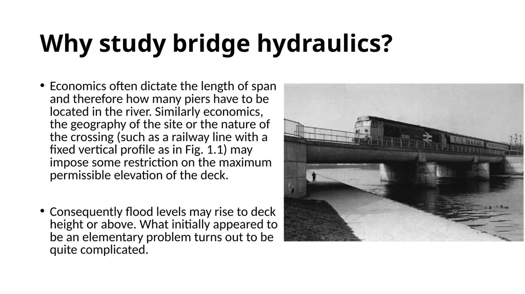
slide4. Why study bridge hydraulics? Economics often dictate the length of span and therefore how many piers have to be located in the river. Similarly economics, the geography of the site or the nature of the crossing (such as a railway line with a fixed vertical profile as in Fig. 1.1) may impose some restriction on the maximum permissible elevation of the deck.
Consequently flood levels may rise to deck height or above. What initially appeared to be an elementary problem turns out to be quite complicated.<br>
slide5. So why study bridge hydraulics? Four answers quickly spring to mind. Nobody can be allowed to build a new bridge that has piers and/or abutments in a river without first being able to prove by calculation or modelling that the resulting backwater will not cause, or significantly exacerbate, flooding of land and property upstream. This is becoming increasingly important as the demand for building land leads to construction on river floodplains that, by definition, are already prone to flooding.<br>
slide6. So why study bridge hydraulics? Four answers quickly spring to mind. 2.
At locations where there is an existing bridge and significant flooding, an analysis may be required to determine how much of the flooding is caused by the bridge and how much by other factors — such as simply too much floodwater to be carried within the river channel. If the analysis shows the bridge to be at fault, then this may be sufficient justification to construct a new structure.<br>
slide7. So why study bridge hydraulics? Four answers quickly spring to mind. 3.
If it is known that a bridge provides a significant obstacle to flow and is responsible for much of the flooding that occurs, with a knowledge of bridge hydraulics it may be possible to design improvement works that will help to alleviate the problem.<br>
slide8. So why study bridge hydraulics? Four answers quickly spring to mind. 4.
In addition to the nature and geometry of the river channel, the shape, spacing and orientation of the bridge piers and abutments will affect the flow through a bridge and the likelihood of scouring of the bed.
Well designed bridges are not immune to this problem, while bridges that are badly designed hydraulically are even more likely to fail and collapse. This can have tragic consequences.
Then,
How can a good design be obtained without a knowledge of bridge hydraulics?<br>
slide9. Early developments in bridge hydraulics Possibly the earliest permanent river bridge of any significance was built somewhere between 810 and 700 BC across the River Euphrates at Babylon (Overman, 1975). The bridge was around 120 m long with stone piers 10 m wide and 22 m in length. A timber deck spanned between the piers, although parts of this were removed at night to stop thieves crossing from one side of the city to the other!<br>
slide10. Early developments in bridge hydraulics The Romans probably represent the finest early bridge engineers, the quality of their road network being apparent even today. They recognised that beam bridges had a limited span, and so employed semicircular arches of up to 30 m. They knew how to build cofferdams and drive piles. A good example of their work is the bridge in Rome now called the Ponte Molle, which was built in 109 BC.<br>
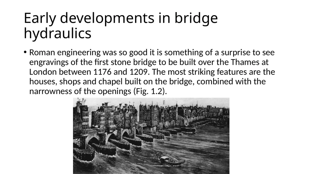
slide11. Early developments in bridge hydraulics Roman engineering was so good it is something of a surprise to see engravings of the first stone bridge to be built over the Thames at London between 1176 and 1209. The most striking features are the houses, shops and chapel built on the bridge, combined with the narrowness of the openings (Fig. 1.2).<br>
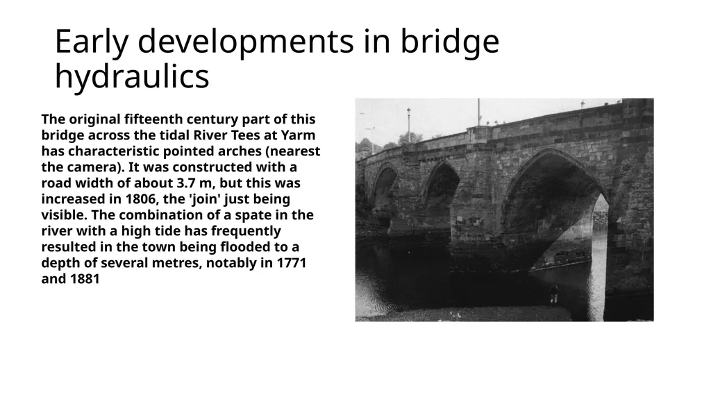
slide12. Early developments in bridge hydraulics The original fifteenth century part of this bridge across the tidal River Tees at Yarm has characteristic pointed arches (nearest the camera). It was constructed with a road width of about 3.7 m, but this was increased in 1806, the 'join' just being visible. The combination of a spate in the river with a high tide has frequently resulted in the town being flooded to a depth of several metres, notably in 1771 and 1881<br>
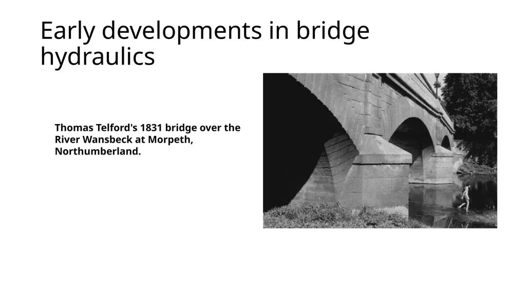
slide13. Early developments in bridge hydraulics Thomas Telford's 1831 bridge over the River Wansbeck at Morpeth, Northumberland.<br>
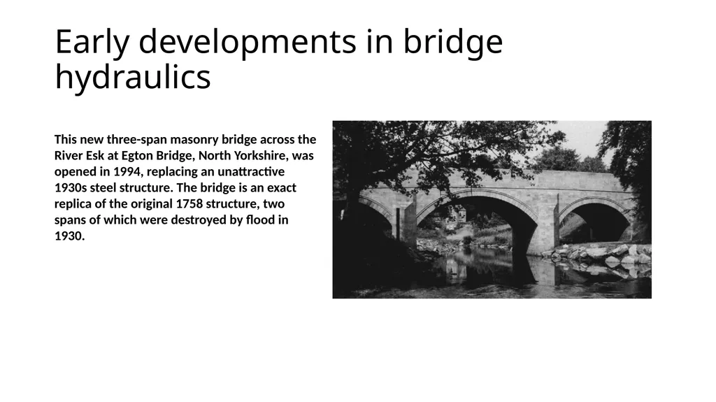
slide14. Early developments in bridge hydraulics This new three-span masonry bridge across the River Esk at Egton Bridge, North Yorkshire, was opened in 1994, replacing an unattractive 1930s steel structure. The bridge is an exact replica of the original 1758 structure, two
spans of which were destroyed by flood in 1930.<br>
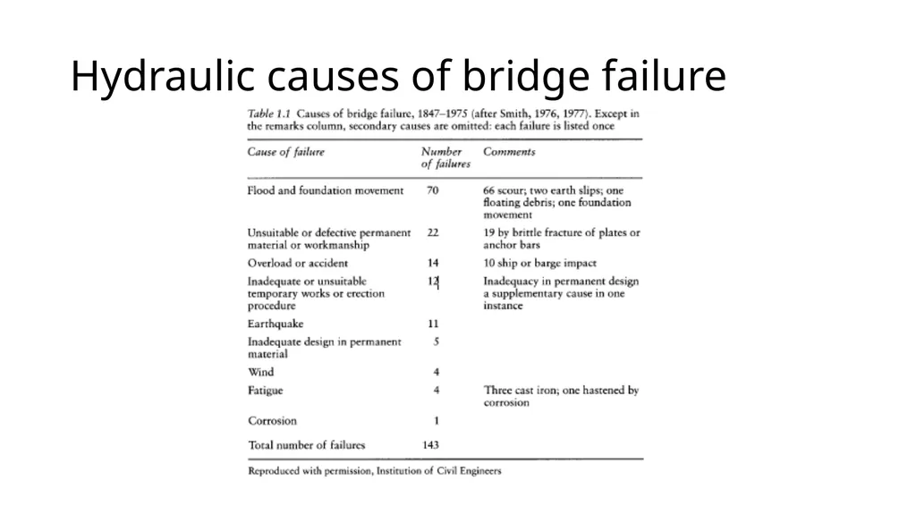
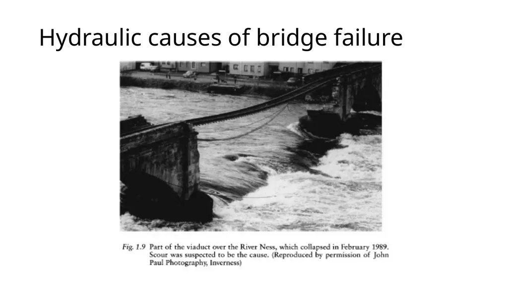
slide15. Hydraulic causes of bridge failure Smith (1976, 1977) studied 143 bridge failures that occurred throughout the world between 1847 and 1975. He grouped the causes of failure into nine categories, as shown in Table 1.1.
Almost half of the failures were due to floods. One flood can wash away the foundations of a large number of bridges at the same time, particularly small structures.
Perhaps the table also shows that engineers pay more attention to structural design than they do to hydraulic considerations?<br>
slide16. Hydraulic causes of bridge failure<br>
slide17. Hydraulic causes of bridge failure<br>
slide18. Hydraulic causes of bridge failure Inadequate waterway openings
There is no universally applicable definition of what constitutes an inadequate opening, but if a bridge is seriously damaged or destroyed by flood then possibly the bridge waterway was not large enough. Regular flooding upstream may also indicate that the opening should be larger.<br>
slide19. Hydraulic causes of bridge failure Inadequate waterway openings
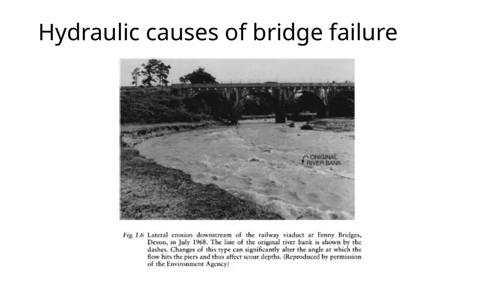
Most of the damage and destruction experienced in Devon and Cornwall has been the result of a small number of extreme storms. For instance, in July 1968 10 bridges were destroyed and a further 19 damaged (Criswell, 1968; George, 1982). The waterway openings of the bridges were too narrow so that the resulting water velocities could easily remove the sedimentary bed materials and erode the foundations.<br>
slide20. Hydraulic causes of bridge failure Inadequate waterway openings
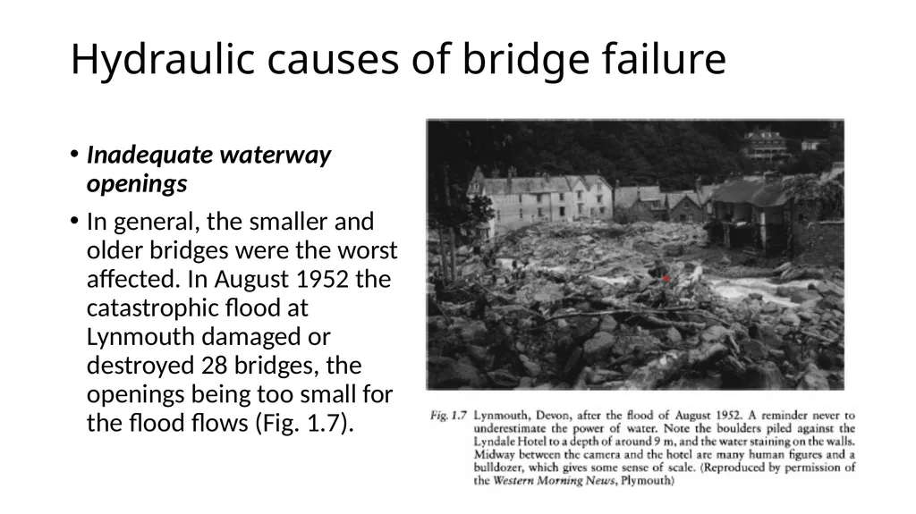
In general, the smaller and older bridges were the worst affected. In August 1952 the catastrophic flood at Lynmouth damaged or destroyed 28 bridges, the openings being too small for the flood flows (Fig. 1.7).<br>
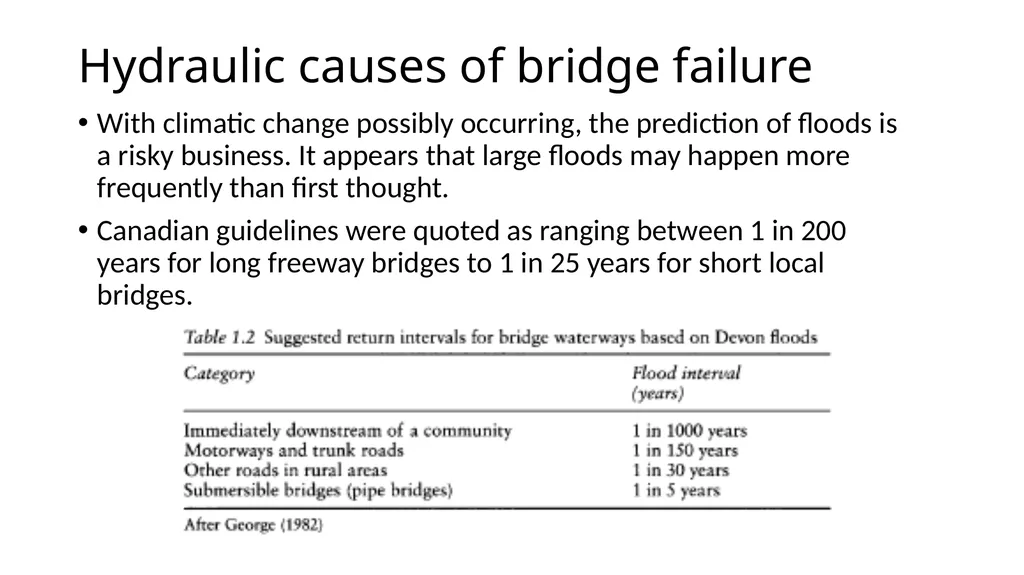
slide21. Hydraulic causes of bridge failure With climatic change possibly occurring, the prediction of floods is a risky business. It appears that large floods may happen more frequently than first thought.
Canadian guidelines were quoted as ranging between 1 in 200 years for long freeway bridges to 1 in 25 years for short local bridges.<br>
slide22. Hydraulic causes of bridge failure Scour effects
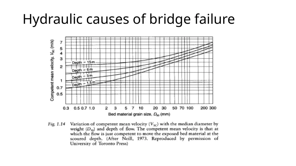
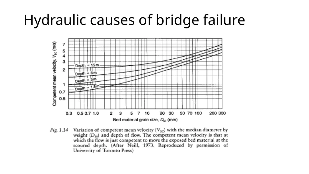
Because the openings of a bridge are usually less than the full width of the river, the water accelerates as it approaches and passes through the waterways.
Consequently the velocity is higher than it would otherwise be, and this can cause scour and undermining of the foundations of the bridge.
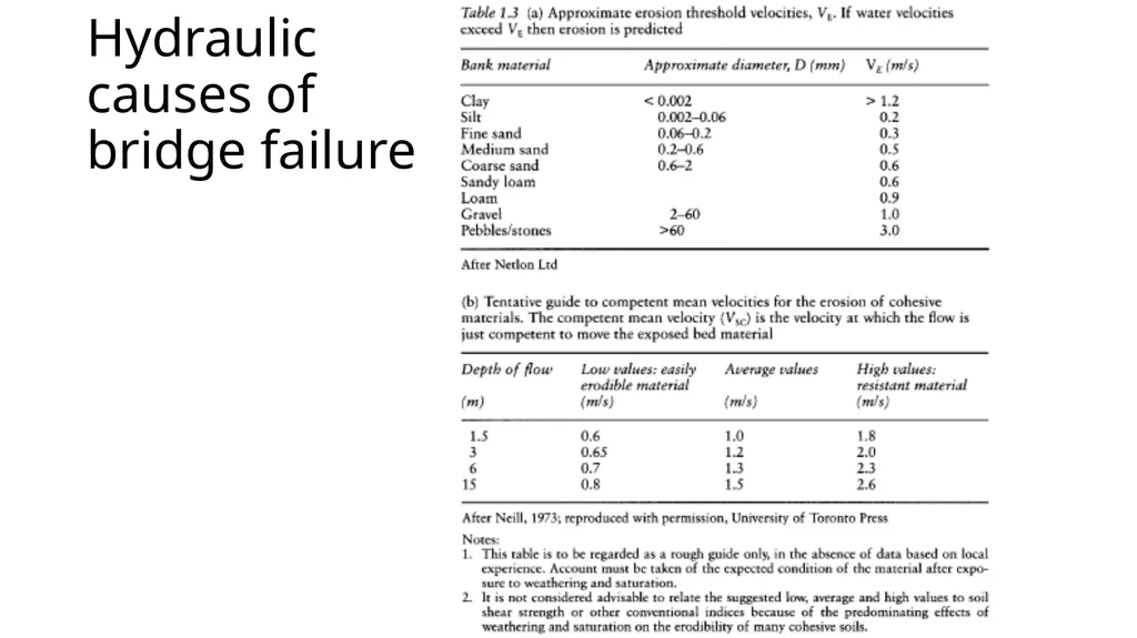
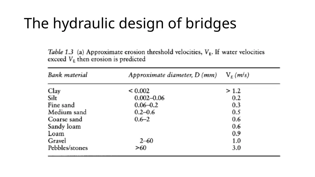
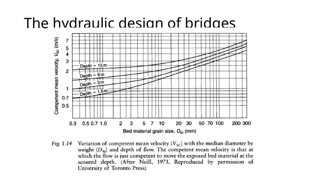
The narrower the openings the larger the velocity, and the finer the material the more easily it can be transported (Fig. 1.14 and Table 1.3).<br>
slide23. Hydraulic causes of bridge failure<br>
slide24. Hydraulic causes of bridge failure<br>
slide25. Hydraulic causes of bridge failure<br>
slide26. Hydraulic causes of bridge failure<br>
slide27. Hydraulic causes of bridge failure Debris
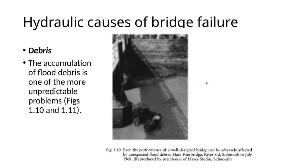
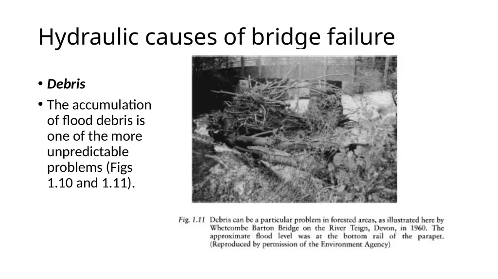
The accumulation of flood debris is one of the more unpredictable problems (Figs 1.10 and 1.11).<br>
slide28. Hydraulic causes of bridge failure Debris
The accumulation of flood debris is one of the more unpredictable problems (Figs 1.10 and 1.11).<br>
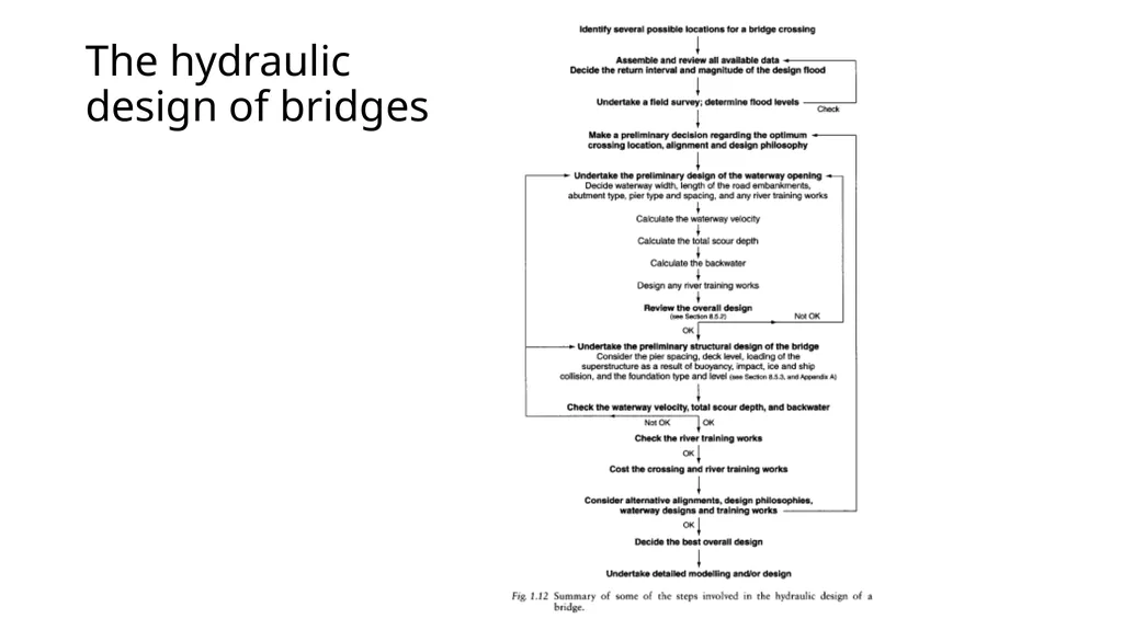
slide29. The hydraulic design of bridges A good hydraulic analysis is an essential part of designing a successful bridge, as illustrated by Table 1.1. Some general guidelines and suggestions are given below, but these are not exhaustive, and must be modified to suit a particular project:
the design of a crossing of national importance over one of the world's great rivers is not the same as constructing an access road to a few isolated properties. Nevertheless, a generalised design process is shown in Fig. 1.12, which may be a useful reminder of some of the steps involved.<br>
slide30. The hydraulic design of bridges<br>
slide31. The hydraulic design of bridges Location
Usually the alignment of a highway or railway will be selected so as to minimise the overall cost, a large part of which may arise from the construction of the river crossings.
Therefore it is sensible to seek an alignment that will minimise the cost of the bridges without significantly adding to the total length of the road. The optimum location and type of crossing is often the one that is most economical in terms of both initial construction and longterm maintainance (a cheap bridge that regularly suffers expensive flood damage is not the best option).<br>
slide32. The hydraulic design of bridges Stable river channels
Generally a bridge will not span the entire floodplain width, so the best site may be the one that offers the highest bridge opening ratio: that is, where the flow in the main channel is largest compared with that over the floodplains.
This helps to optimise the hydraulic efficiency and minimise the backwater.<br>
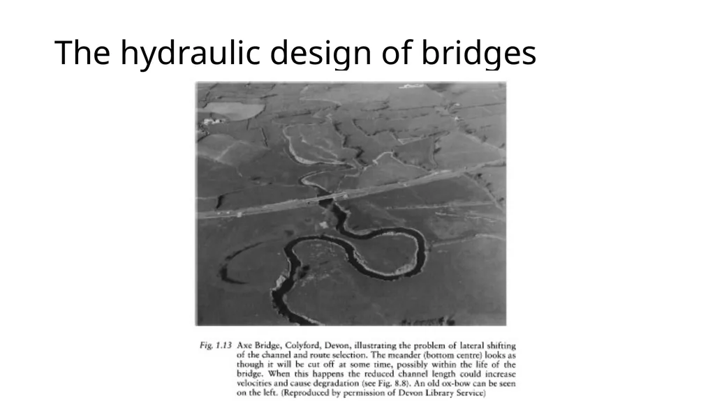
slide33. The hydraulic design of bridges Semi-stable and unstable river channels
If the river channel is gradually moving, frequently shifts course or meanders periodically then site selection is more complex (Fig. 1.13). Assuming that the bridge will not span the entire floodplain width, some form of river training works may be needed to stabilise the channel and ensure that the flow approaches the bridge as planned, or does not miss the waterway opening altogether during flood.<br>
slide34. The hydraulic design of bridges<br>
slide35. The hydraulic design of bridges Examination of existing data
Existing data that are already available or easy to obtain should be examined before embarking on an expensive field investigation.<br>
slide36. The hydraulic design of bridges The sort of data required are as follows:
TOPOGRAPHIC MAPS
To determine channel and floodplain width, to help identify possible crossing sites, to obtain the channel gradient, and to indicate floodplain use.
The land use may help decide the maximum permissible backwater.<br>
slide37. The hydraulic design of bridges AIRPHOTOS AND SATELLITE PHOTOS
Largely as for topographic maps.
CHARTS AND TIDE TABLES
For navigable waters charts may be available showing widths and depths, while tide tables will help determine the range of depths in estuaries. Any information regarding wave heights should also be obtained.<br>
slide38. The hydraulic design of bridges GEOLOGICAL MAPS, SOIL MAPS AND GEOLOGICAL MEMOIRS
May provide some details about the local geology and the likelihood of the channel migrating or of scour being a problem.
CONSTRUCTION DETAILS OF EXISTING BRIDGES
May yield some data regarding the geology, depth of foundations required, the design flood and the waterway dimensions. Have these bridges been successful?
Are all of their spans used?
Are the bridges bypassed during flood?
Are their decks high enough?
Has serious scour occurred?
Have river training works been added subsequently?
Is there another bridge or structure that will interfere hydraulically with the proposed crossing or vice versa?<br>
slide39. The hydraulic design of bridges HYDROLOGICAL DATA
Such as gauging station records, annual maxima, stage—discharge relationship, and flow—duration curve. These are needed to help identify the design flood and the maximum likely water level, and to plan construction work.<br>
slide40. The hydraulic design of bridges METEOROLOGICAL DATA
Rainfall depths, and intensities, snowfall and snow-melt, temperature range and wind speed. These data may help in assessing the possibility of flash flood, and of ice formation and ice loading on the superstructure. If appropriate, the wind speed can be used to assess potential wave heights. Both ice and waves may have to be allowed for when determining the height of the deck.<br>
slide41. The hydraulic design of bridges RIVER CHANNEL DATA
Things such as the roughness of the channel and floodplains (say for use in the Manning equation) are never easy to determine at the best of times and may have to be inferred initially from photographs or from preliminary visits to the site.<br>
slide42. The hydraulic design of bridges SPECIAL CONSIDERATIONS
Such as river regulation, ice flows, logging, or navigation that will require additional clearance between the flood level and the bridge superstructure.
Environmental considerations are rightly becoming increasingly important and may determine whether or not river training works, spur dykes or bypass channels can be constructed, and may also influence the appearance and design of the bridge and its highway embankments.<br>
slide43. The hydraulic design of bridges Field investigations
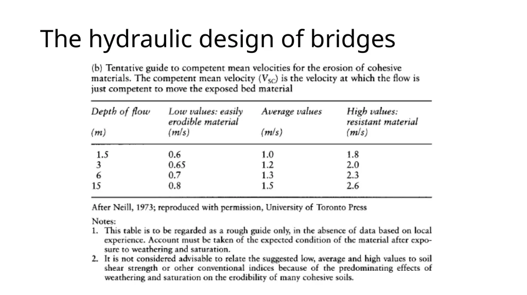
These are typically used to confirm the accuracy of the data above and to provide missing information: for example, the location of rock outcrops and hydraulic control points within the river, such as rapids. Samples of bed and bank material can be obtained for analysis to determine composition, grading and D50 value, and to assess scour and erosion potential (Table 1.3).<br>
slide44. The hydraulic design of bridges<br>
slide45. The hydraulic design of bridges<br>
slide46. The hydraulic design of bridges General hydraulic design philosophy
In addition to deciding the relative length of the bridge opening and any highway embankments, the designer will often have some idea as to whether the bridge will be a single or multispan structure from the channel and floodplain width and a knowledge of the economic importance of the crossing.<br>
slide47. The hydraulic design of bridges Preliminary design of the bridge waterway
From the above it should be possible to identify one preferred location for the waterway. The design procedure can be shortened if it is already known what the pier arrangement will be, otherwise an educated guess is needed.
Pier spacing depends upon economics, ground conditions, navigation requirements, backwater restrictions, potential scour, and aesthetics. Of course, from the hydraulic perspective a single-span opening is preferable, but if piers are unavoidable then use as few as possible.<br>
slide48. The hydraulic design of bridges Preliminary design of the bridge waterway
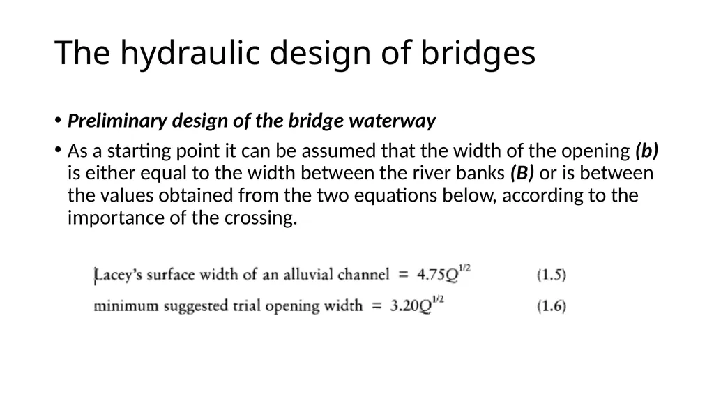
As a starting point it can be assumed that the width of the opening (b) is either equal to the width between the river banks (B) or is between the values obtained from the two equations below, according to the importance of the crossing.<br>
slide49. The hydraulic design of bridges<br>
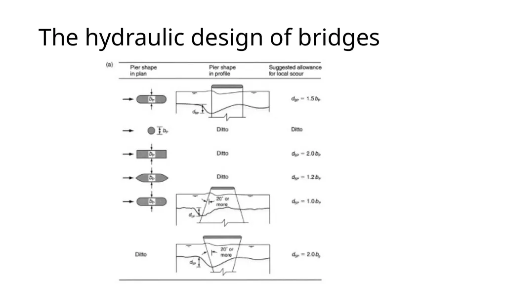
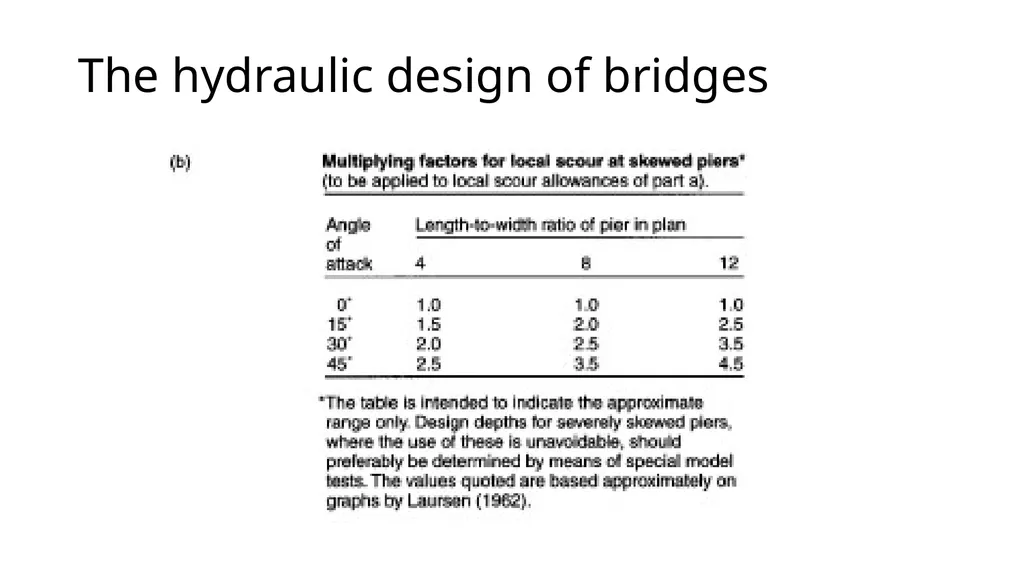
slide50. The hydraulic design of bridges If piers are located in the river channel then the approximate pier scour depth (dSP) shown in Fig. 1.15 should be added to (dsc). Note part (b) of the diagram, which is needed when the approach flow is at an angle to the piers.<br>
slide51. The hydraulic design of bridges<br>
slide52. The hydraulic design of bridges<br>
slide53. The hydraulic design of bridges Preliminary structural design of the bridge
This includes deciding the level of the deck and the foundation details, which may be related to the maximum scour depth
Having established the basic structural form of the bridge, ensure that any river training works considered necessary during the hydraulic design are still appropriate and effective.
If everything is satisfactory, a costing of the bridge, approaches and training works can be obtained.<br>
slide54. The hydraulic design of bridges Consider alternatives
Having found one acceptable design, the opportunity should be taken to revisit the original data and to evaluate whether or not an alternative location or different design approach would yield a cheaper and/or more effective alternative. If the existing design proves to be superior, the design can be finalised.<br>
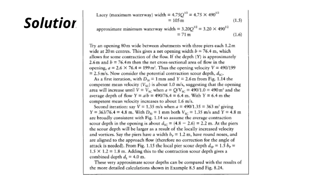
slide55. Example A preliminary hydraulic design is required for a bridge to cross a 60 m wide main channel with floodplains 150 m wide on each side when the discharge is 490m3/s. The corresponding flow depth is 2.6m in the main channel and, since the river has banks 1.0 m high, 1.6 m on the immediately adjoining floodplain. The diameter of the sand bed material is D50 = 1.0 mm.<br>
slide56. Solution<br>
slide57. 2 How a bridge affects river flow When a bridge is placed in a river it forms a narrowing of the natural channel and an obstacle to the flow. This results in a loss of energy as the flow contracts, passes through the bridge and then, most significantly, reexpands back to the full channel width. To provide the additional head necessary to overcome the energy loss the upstream water level increases above that which would be usually experienced without the bridge. This additional head is called the afflux, and its variation with distance upstream is called the backwater profile. The smaller the opening, the greater the afflux and backwater.<br>
slide58. 2 How a bridge affects river flow When investigating whether or not a bridge is (or will be) the primary cause of flooding the hydraulic capacity of the main river channel without the bridge (QR) should be compared with the capacity of the bridge waterway (Qw ) and the design flood (QDF ) . Then as a rough guide:
QR < Qw the bridge is relatively blameless;
if QR < QDF inundation of the floodplains would occur without the bridge;
if Q w < Q R the bridge forms an obstacle to flow and may cause or exacerbate flooding;
if Qw < QDF the waterway is under designed;
if Q w > Q D F the waterway is overdesigned or has a margin of safety.<br>
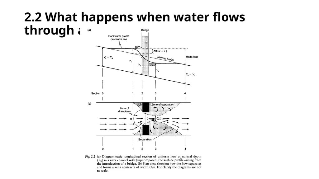
slide59. 2.2 What happens when water flows through a bridge In the reach affected by the backwater the depth will be greater than normal, so the velocity and energy loss are less than would otherwise occur.
Unless the constriction is very severe the flow is usually subcritical, with gradually varied flow upstream and downstream of the structure and rapidly varying flow at the bridge.<br>
slide60. 2.2 What happens when water flows through a bridge<br>
slide61. 2.2 What happens when water flows through a bridge<br>
slide62. 2.2 What happens when water flows through a bridge<br>
slide63. 2.3 Afflux, piezometric head loss and energy loss Regardless of whether it is a proposed or existing bridge that is to be analysed, most hydraulic investigations require an estimate of the change in water level caused by the structure. This means that the afflux and the piezometric head loss are required. The energy loss includes a consideration of the change in both the velocity head and the piezometric head.<br>
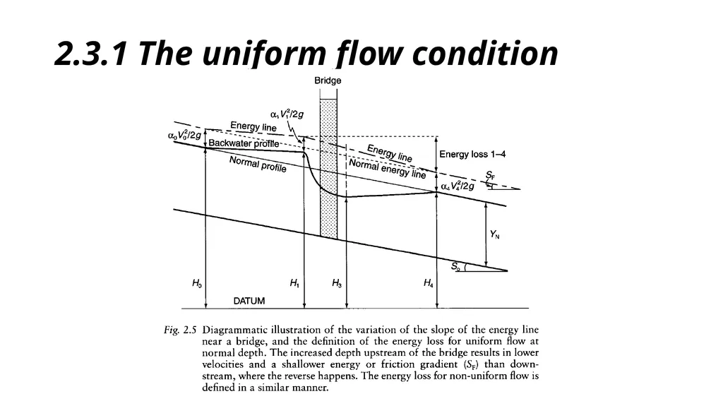
slide64. 2.3.1 The uniform flow condition Because it is the simplest, the uniform flow condition will be used initially to define and illustrate the afflux and head loss across a bridge. For the situation shown in Fig. 2.2a, at any particular discharge:
maximum afflux, H* = Y1 — YN
where Y1 is the water depth (m) at section 1 and YN is the normal depth (m).<br>
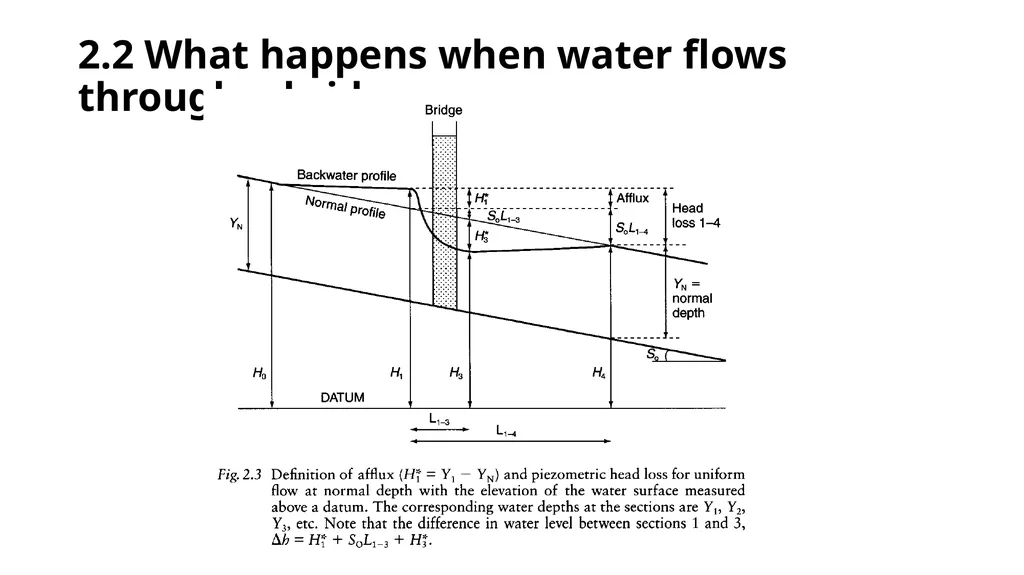
slide65. 2.3.1 The uniform flow condition Here the elevation of the water surface above a datum is used. Again the maximum afflux (H*) is the difference in water level with and without the bridge, but it is now apparent that
H* = H1- (H4 + S0 L1-4) (2.2)
where H1 and H4 are the elevation of the water surface (m) at sections 1 and
4 respectively, S0 is the dimensionless gradient of the channel and L1-4 is the plan distance (m) between sections 1 and 4. With existing bridges the difference in bed level (S0 L1-4) can be measured. Note that (H1 — H3) is greater than the value obtained from equation 2.2 but is not the true afflux, simply the difference in water level across the constriction.<br>
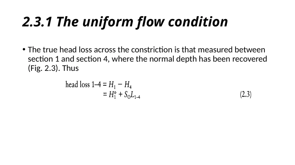
slide66. 2.3.1 The uniform flow condition The true head loss across the constriction is that measured between section 1 and section 4, where the normal depth has been recovered (Fig. 2.3). Thus<br>
slide67. 2.3.1 The uniform flow condition<br>
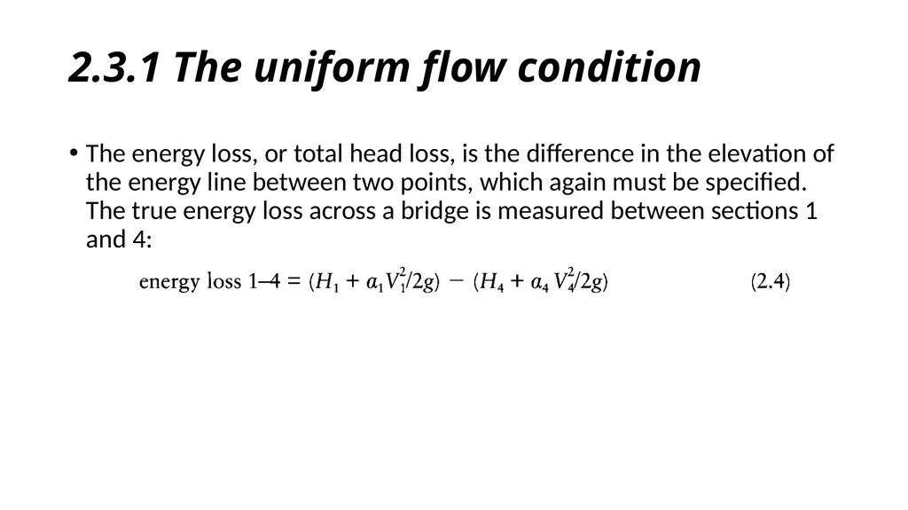
slide68. 2.3.1 The uniform flow condition The energy loss, or total head loss, is the difference in the elevation of the energy line between two points, which again must be specified. The true energy loss across a bridge is measured between sections 1 and 4:<br>
slide69. 2.3.1 The uniform flow condition The energy loss caused by a bridge can be assumed to arise from three main things:
contraction of the flow caused by the abutments, noses of the piers and, when the opening is submerged, the soffit or deck of the bridge (15%);
friction between the water and the surfaces of the piers, abutments and, when the opening is submerged, the soffit of the bridge (20%);
expansion of the live stream downstream of the bridge (65%).<br>
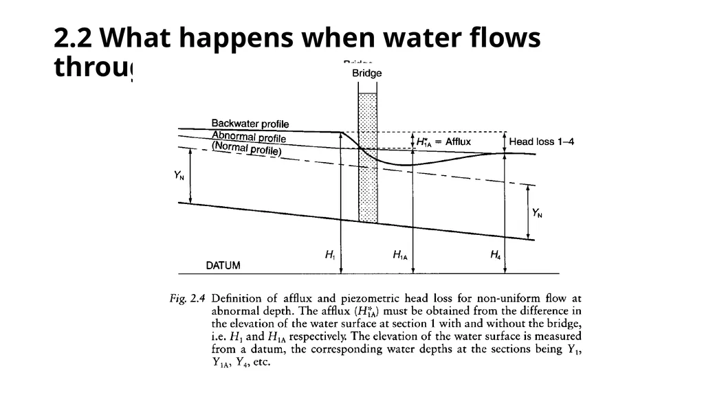
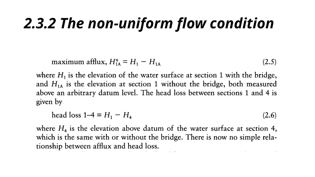
slide70. 2.3.2 The non-uniform flow condition With non-uniform flow and abnormal stages (suffix A below) that are greater than the normal depth, the calculation of the afflux is not quite so simple.
Consequently if an existing bridge is being investigated this abnormal profile will have to be computed from a backwater analysis; if the bridge has not yet been constructed it can be either measured in the field or calculated.<br>
slide71. 2.3.2 The non-uniform flow condition<br>
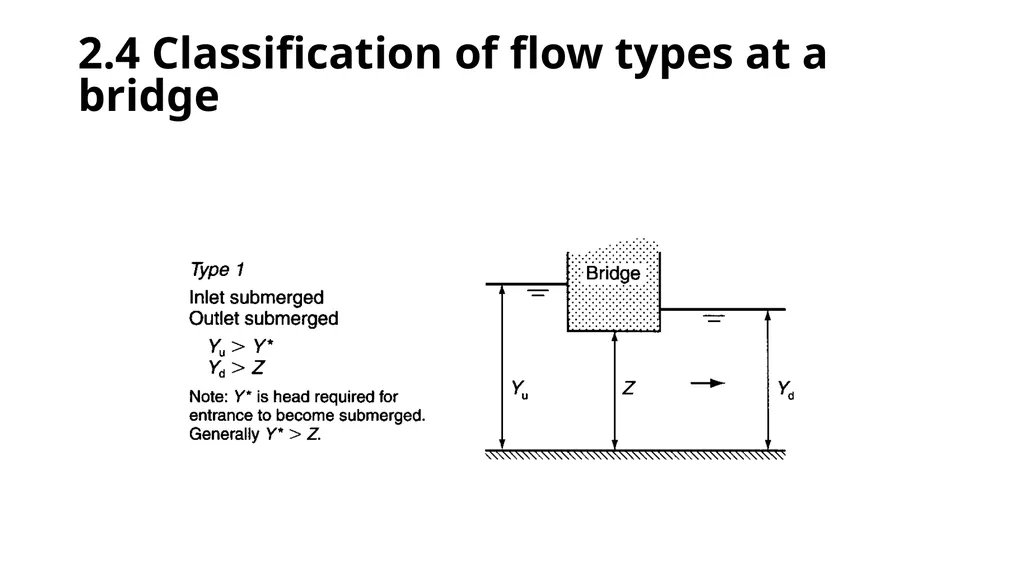
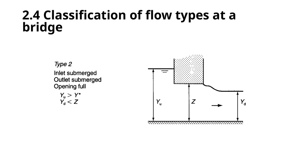
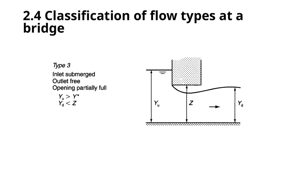
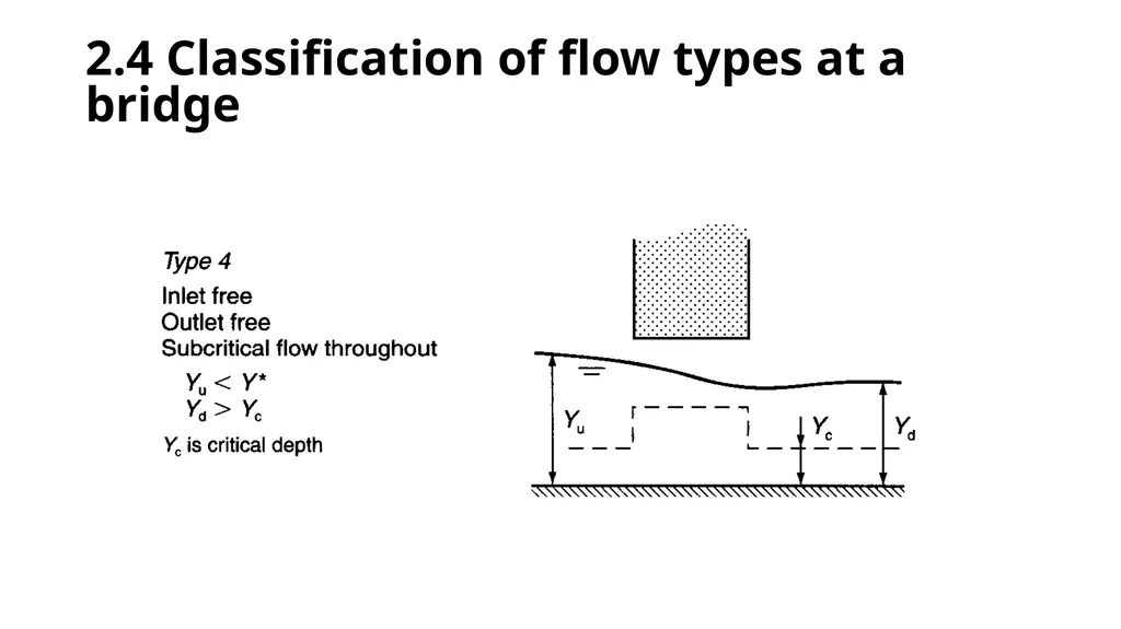
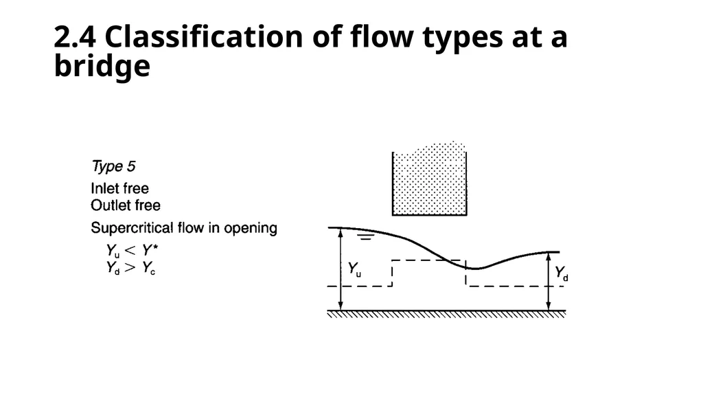
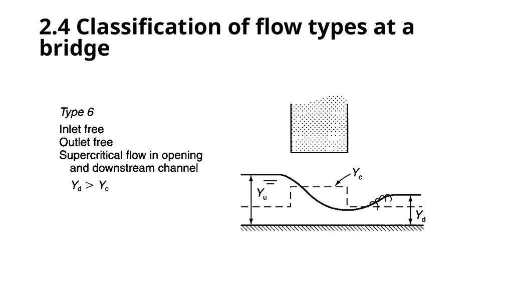
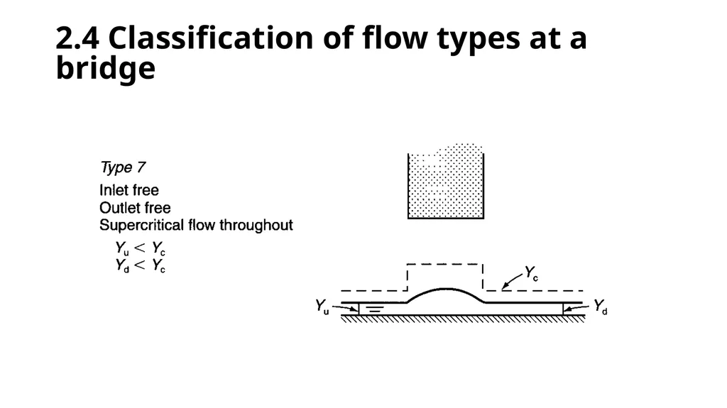
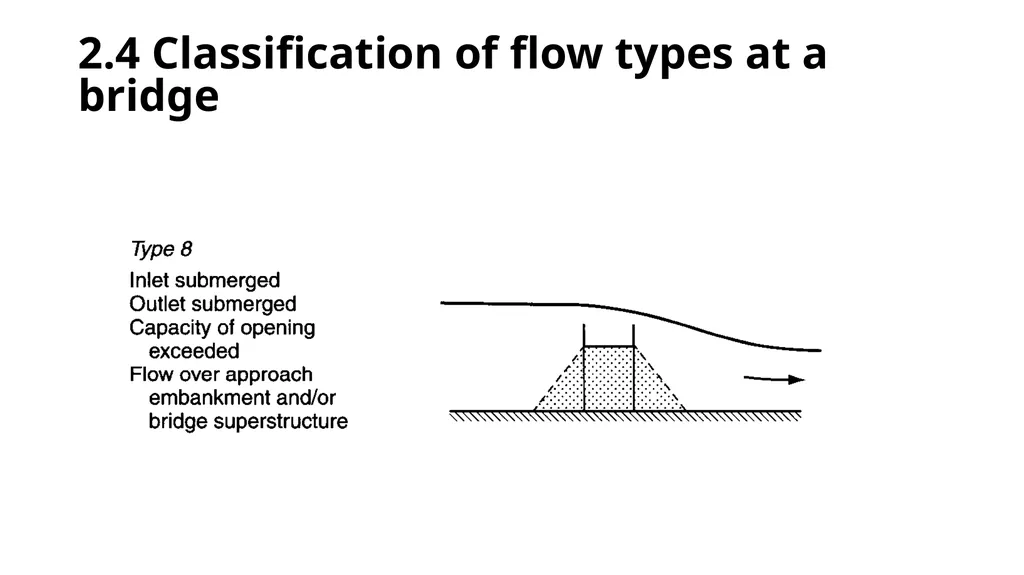
slide72. 2.4 Classification of flow types at a bridge There are many types of flow that can occur at a bridge site depending upon the upstream and downstream stage, the discharge, the severity of the constriction, and its geometry.<br>
slide73. 2.4 Classification of flow types at a bridge<br>
slide74. 2.4 Classification of flow types at a bridge<br>
slide75. 2.4 Classification of flow types at a bridge<br>
slide76. 2.4 Classification of flow types at a bridge<br>
slide77. 2.4 Classification of flow types at a bridge<br>
slide78. 2.4 Classification of flow types at a bridge<br>
slide79. 2.4 Classification of flow types at a bridge<br>
slide80. 2.4 Classification of flow types at a bridge<br>
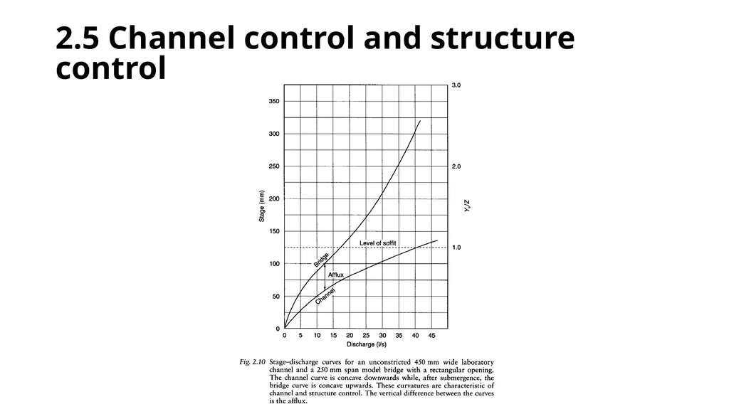
slide81. 2.5 Channel control and structure control This is another generic classification that incorporates some of the factors described above. The classification depends upon whether the stage and discharge at the bridge site are controlled by the channel or by the structure.<br>
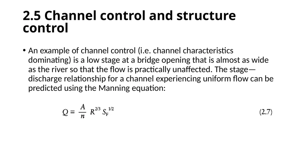
slide82. 2.5 Channel control and structure control An example of channel control (i.e. channel characteristics dominating) is a low stage at a bridge opening that is almost as wide as the river so that the flow is practically unaffected. The stage—discharge relationship for a channel experiencing uniform flow can be predicted using the Manning equation:<br>
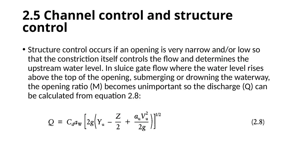
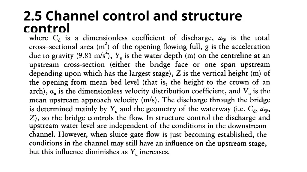
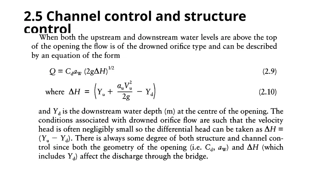
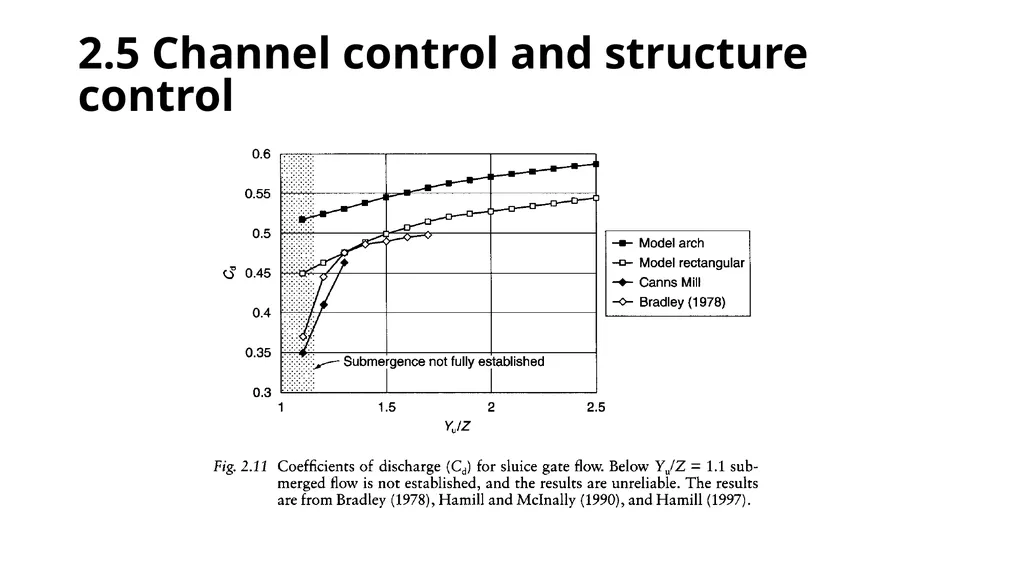
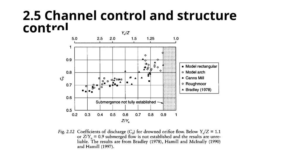
slide83. 2.5 Channel control and structure control Structure control occurs if an opening is very narrow and/or low so that the constriction itself controls the flow and determines the upstream water level. In sluice gate flow where the water level rises above the top of the opening, submerging or drowning the waterway, the opening ratio (M) becomes unimportant so the discharge (Q) can be calculated from equation 2.8:<br>
slide84. 2.5 Channel control and structure control<br>
slide85. 2.5 Channel control and structure control<br>
slide86. 2.5 Channel control and structure control<br>
slide87. 2.5 Channel control and structure control<br>
slide88. 2.5 Channel control and structure control<br>
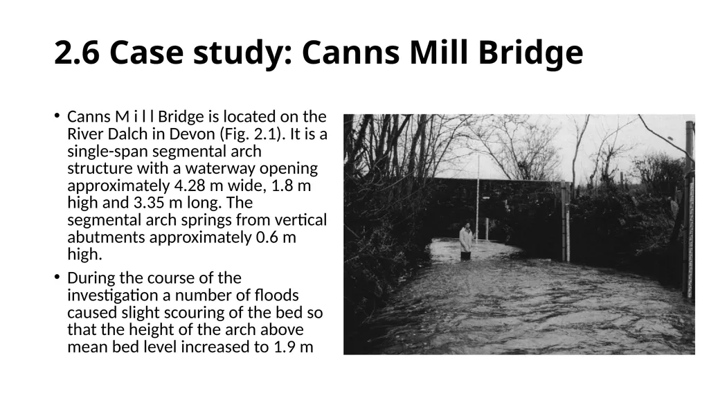
slide89. 2.6 Case study: Canns Mill Bridge Canns M i l l Bridge is located on the River Dalch in Devon (Fig. 2.1). It is a single-span segmental arch structure with a waterway opening approximately 4.28 m wide, 1.8 m high and 3.35 m long. The segmental arch springs from vertical abutments approximately 0.6 m high.
During the course of the investigation a number of floods caused slight scouring of the bed so that the height of the arch above mean bed level increased to 1.9 m<br>
slide90. 2.6 Case study: Canns Mill Bridge<br>
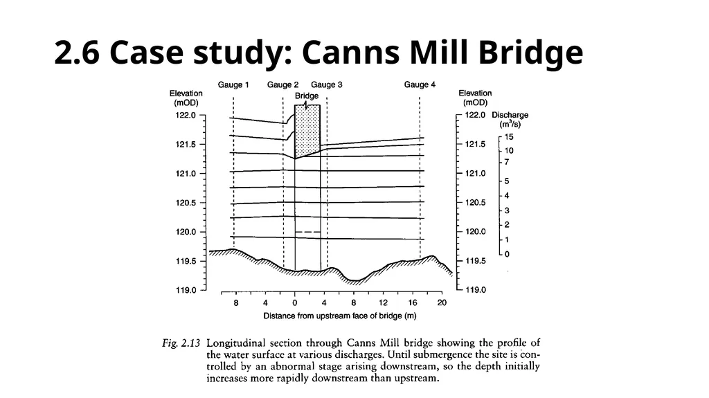
slide91. 2.6 Case study: Canns Mill Bridge The largest event recorded was about 15m/s, which caused the water level to rise 0.76 m above the upstream soffit of the bridge, equivalent to Yu/Z = 1.4. This level is indicated by the white mark on the bridge face in Fig. 2.15.
Typically a shallow standing wave formed against the face, moving further upstream as the degree of submergence increased. At the downstream face the water level was probably around 0.2 m above the downstream soffit of the bridge (which is higher than the upstream soffit).
There was significant overbank flow both upstream and downstream of
the bridge, but no bypass flow around it.<br>
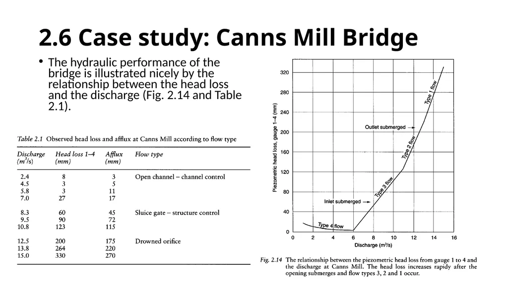
slide92. 2.6 Case study: Canns Mill Bridge The hydraulic performance of the bridge is illustrated nicely by the relationship between the head loss and the discharge (Fig. 2.14 and Table 2.1).<br>
slide93. 2.6 Case study: Canns Mill Bridge Prior to submergence of the waterway, the river channel rather than the bridge was the primary cause of flooding, after which the afflux added up to 270 mm to the upstream stage. Thus severe flooding would occur without the bridge. This again demonstrates the need to fully understand the nature of a site and the prevailing flow conditions before considering either improvement works or a replacement bridge.<br>
slide2. Text Book: Bridge Hydraulics by Les Hamill Taylor & Francis Publication<br>
slide3. Why study bridge hydraulics? Many people, indeed many engineers, who are not familiar with the subject imagine that constructing a bridge across a river is entirely a problem in structural engineering.
They assume that the bridge opening can be made so large that it will completely span the river at such a height that floodwater will never rise anywhere near the deck.
If this was always true there would be little need to study bridge hydraulics, but in reality things arerarely this simple.<br>
slide4. Why study bridge hydraulics? Economics often dictate the length of span and therefore how many piers have to be located in the river. Similarly economics, the geography of the site or the nature of the crossing (such as a railway line with a fixed vertical profile as in Fig. 1.1) may impose some restriction on the maximum permissible elevation of the deck.
Consequently flood levels may rise to deck height or above. What initially appeared to be an elementary problem turns out to be quite complicated.<br>
slide5. So why study bridge hydraulics? Four answers quickly spring to mind. Nobody can be allowed to build a new bridge that has piers and/or abutments in a river without first being able to prove by calculation or modelling that the resulting backwater will not cause, or significantly exacerbate, flooding of land and property upstream. This is becoming increasingly important as the demand for building land leads to construction on river floodplains that, by definition, are already prone to flooding.<br>
slide6. So why study bridge hydraulics? Four answers quickly spring to mind. 2.
At locations where there is an existing bridge and significant flooding, an analysis may be required to determine how much of the flooding is caused by the bridge and how much by other factors — such as simply too much floodwater to be carried within the river channel. If the analysis shows the bridge to be at fault, then this may be sufficient justification to construct a new structure.<br>
slide7. So why study bridge hydraulics? Four answers quickly spring to mind. 3.
If it is known that a bridge provides a significant obstacle to flow and is responsible for much of the flooding that occurs, with a knowledge of bridge hydraulics it may be possible to design improvement works that will help to alleviate the problem.<br>
slide8. So why study bridge hydraulics? Four answers quickly spring to mind. 4.
In addition to the nature and geometry of the river channel, the shape, spacing and orientation of the bridge piers and abutments will affect the flow through a bridge and the likelihood of scouring of the bed.
Well designed bridges are not immune to this problem, while bridges that are badly designed hydraulically are even more likely to fail and collapse. This can have tragic consequences.
Then,
How can a good design be obtained without a knowledge of bridge hydraulics?<br>
slide9. Early developments in bridge hydraulics Possibly the earliest permanent river bridge of any significance was built somewhere between 810 and 700 BC across the River Euphrates at Babylon (Overman, 1975). The bridge was around 120 m long with stone piers 10 m wide and 22 m in length. A timber deck spanned between the piers, although parts of this were removed at night to stop thieves crossing from one side of the city to the other!<br>
slide10. Early developments in bridge hydraulics The Romans probably represent the finest early bridge engineers, the quality of their road network being apparent even today. They recognised that beam bridges had a limited span, and so employed semicircular arches of up to 30 m. They knew how to build cofferdams and drive piles. A good example of their work is the bridge in Rome now called the Ponte Molle, which was built in 109 BC.<br>
slide11. Early developments in bridge hydraulics Roman engineering was so good it is something of a surprise to see engravings of the first stone bridge to be built over the Thames at London between 1176 and 1209. The most striking features are the houses, shops and chapel built on the bridge, combined with the narrowness of the openings (Fig. 1.2).<br>
slide12. Early developments in bridge hydraulics The original fifteenth century part of this bridge across the tidal River Tees at Yarm has characteristic pointed arches (nearest the camera). It was constructed with a road width of about 3.7 m, but this was increased in 1806, the 'join' just being visible. The combination of a spate in the river with a high tide has frequently resulted in the town being flooded to a depth of several metres, notably in 1771 and 1881<br>
slide13. Early developments in bridge hydraulics Thomas Telford's 1831 bridge over the River Wansbeck at Morpeth, Northumberland.<br>
slide14. Early developments in bridge hydraulics This new three-span masonry bridge across the River Esk at Egton Bridge, North Yorkshire, was opened in 1994, replacing an unattractive 1930s steel structure. The bridge is an exact replica of the original 1758 structure, two
spans of which were destroyed by flood in 1930.<br>
slide15. Hydraulic causes of bridge failure Smith (1976, 1977) studied 143 bridge failures that occurred throughout the world between 1847 and 1975. He grouped the causes of failure into nine categories, as shown in Table 1.1.
Almost half of the failures were due to floods. One flood can wash away the foundations of a large number of bridges at the same time, particularly small structures.
Perhaps the table also shows that engineers pay more attention to structural design than they do to hydraulic considerations?<br>
slide16. Hydraulic causes of bridge failure<br>
slide17. Hydraulic causes of bridge failure<br>
slide18. Hydraulic causes of bridge failure Inadequate waterway openings
There is no universally applicable definition of what constitutes an inadequate opening, but if a bridge is seriously damaged or destroyed by flood then possibly the bridge waterway was not large enough. Regular flooding upstream may also indicate that the opening should be larger.<br>
slide19. Hydraulic causes of bridge failure Inadequate waterway openings
Most of the damage and destruction experienced in Devon and Cornwall has been the result of a small number of extreme storms. For instance, in July 1968 10 bridges were destroyed and a further 19 damaged (Criswell, 1968; George, 1982). The waterway openings of the bridges were too narrow so that the resulting water velocities could easily remove the sedimentary bed materials and erode the foundations.<br>
slide20. Hydraulic causes of bridge failure Inadequate waterway openings
In general, the smaller and older bridges were the worst affected. In August 1952 the catastrophic flood at Lynmouth damaged or destroyed 28 bridges, the openings being too small for the flood flows (Fig. 1.7).<br>
slide21. Hydraulic causes of bridge failure With climatic change possibly occurring, the prediction of floods is a risky business. It appears that large floods may happen more frequently than first thought.
Canadian guidelines were quoted as ranging between 1 in 200 years for long freeway bridges to 1 in 25 years for short local bridges.<br>
slide22. Hydraulic causes of bridge failure Scour effects
Because the openings of a bridge are usually less than the full width of the river, the water accelerates as it approaches and passes through the waterways.
Consequently the velocity is higher than it would otherwise be, and this can cause scour and undermining of the foundations of the bridge.
The narrower the openings the larger the velocity, and the finer the material the more easily it can be transported (Fig. 1.14 and Table 1.3).<br>
slide23. Hydraulic causes of bridge failure<br>
slide24. Hydraulic causes of bridge failure<br>
slide25. Hydraulic causes of bridge failure<br>
slide26. Hydraulic causes of bridge failure<br>
slide27. Hydraulic causes of bridge failure Debris
The accumulation of flood debris is one of the more unpredictable problems (Figs 1.10 and 1.11).<br>
slide28. Hydraulic causes of bridge failure Debris
The accumulation of flood debris is one of the more unpredictable problems (Figs 1.10 and 1.11).<br>
slide29. The hydraulic design of bridges A good hydraulic analysis is an essential part of designing a successful bridge, as illustrated by Table 1.1. Some general guidelines and suggestions are given below, but these are not exhaustive, and must be modified to suit a particular project:
the design of a crossing of national importance over one of the world's great rivers is not the same as constructing an access road to a few isolated properties. Nevertheless, a generalised design process is shown in Fig. 1.12, which may be a useful reminder of some of the steps involved.<br>
slide30. The hydraulic design of bridges<br>
slide31. The hydraulic design of bridges Location
Usually the alignment of a highway or railway will be selected so as to minimise the overall cost, a large part of which may arise from the construction of the river crossings.
Therefore it is sensible to seek an alignment that will minimise the cost of the bridges without significantly adding to the total length of the road. The optimum location and type of crossing is often the one that is most economical in terms of both initial construction and longterm maintainance (a cheap bridge that regularly suffers expensive flood damage is not the best option).<br>
slide32. The hydraulic design of bridges Stable river channels
Generally a bridge will not span the entire floodplain width, so the best site may be the one that offers the highest bridge opening ratio: that is, where the flow in the main channel is largest compared with that over the floodplains.
This helps to optimise the hydraulic efficiency and minimise the backwater.<br>
slide33. The hydraulic design of bridges Semi-stable and unstable river channels
If the river channel is gradually moving, frequently shifts course or meanders periodically then site selection is more complex (Fig. 1.13). Assuming that the bridge will not span the entire floodplain width, some form of river training works may be needed to stabilise the channel and ensure that the flow approaches the bridge as planned, or does not miss the waterway opening altogether during flood.<br>
slide34. The hydraulic design of bridges<br>
slide35. The hydraulic design of bridges Examination of existing data
Existing data that are already available or easy to obtain should be examined before embarking on an expensive field investigation.<br>
slide36. The hydraulic design of bridges The sort of data required are as follows:
TOPOGRAPHIC MAPS
To determine channel and floodplain width, to help identify possible crossing sites, to obtain the channel gradient, and to indicate floodplain use.
The land use may help decide the maximum permissible backwater.<br>
slide37. The hydraulic design of bridges AIRPHOTOS AND SATELLITE PHOTOS
Largely as for topographic maps.
CHARTS AND TIDE TABLES
For navigable waters charts may be available showing widths and depths, while tide tables will help determine the range of depths in estuaries. Any information regarding wave heights should also be obtained.<br>
slide38. The hydraulic design of bridges GEOLOGICAL MAPS, SOIL MAPS AND GEOLOGICAL MEMOIRS
May provide some details about the local geology and the likelihood of the channel migrating or of scour being a problem.
CONSTRUCTION DETAILS OF EXISTING BRIDGES
May yield some data regarding the geology, depth of foundations required, the design flood and the waterway dimensions. Have these bridges been successful?
Are all of their spans used?
Are the bridges bypassed during flood?
Are their decks high enough?
Has serious scour occurred?
Have river training works been added subsequently?
Is there another bridge or structure that will interfere hydraulically with the proposed crossing or vice versa?<br>
slide39. The hydraulic design of bridges HYDROLOGICAL DATA
Such as gauging station records, annual maxima, stage—discharge relationship, and flow—duration curve. These are needed to help identify the design flood and the maximum likely water level, and to plan construction work.<br>
slide40. The hydraulic design of bridges METEOROLOGICAL DATA
Rainfall depths, and intensities, snowfall and snow-melt, temperature range and wind speed. These data may help in assessing the possibility of flash flood, and of ice formation and ice loading on the superstructure. If appropriate, the wind speed can be used to assess potential wave heights. Both ice and waves may have to be allowed for when determining the height of the deck.<br>
slide41. The hydraulic design of bridges RIVER CHANNEL DATA
Things such as the roughness of the channel and floodplains (say for use in the Manning equation) are never easy to determine at the best of times and may have to be inferred initially from photographs or from preliminary visits to the site.<br>
slide42. The hydraulic design of bridges SPECIAL CONSIDERATIONS
Such as river regulation, ice flows, logging, or navigation that will require additional clearance between the flood level and the bridge superstructure.
Environmental considerations are rightly becoming increasingly important and may determine whether or not river training works, spur dykes or bypass channels can be constructed, and may also influence the appearance and design of the bridge and its highway embankments.<br>
slide43. The hydraulic design of bridges Field investigations
These are typically used to confirm the accuracy of the data above and to provide missing information: for example, the location of rock outcrops and hydraulic control points within the river, such as rapids. Samples of bed and bank material can be obtained for analysis to determine composition, grading and D50 value, and to assess scour and erosion potential (Table 1.3).<br>
slide44. The hydraulic design of bridges<br>
slide45. The hydraulic design of bridges<br>
slide46. The hydraulic design of bridges General hydraulic design philosophy
In addition to deciding the relative length of the bridge opening and any highway embankments, the designer will often have some idea as to whether the bridge will be a single or multispan structure from the channel and floodplain width and a knowledge of the economic importance of the crossing.<br>
slide47. The hydraulic design of bridges Preliminary design of the bridge waterway
From the above it should be possible to identify one preferred location for the waterway. The design procedure can be shortened if it is already known what the pier arrangement will be, otherwise an educated guess is needed.
Pier spacing depends upon economics, ground conditions, navigation requirements, backwater restrictions, potential scour, and aesthetics. Of course, from the hydraulic perspective a single-span opening is preferable, but if piers are unavoidable then use as few as possible.<br>
slide48. The hydraulic design of bridges Preliminary design of the bridge waterway
As a starting point it can be assumed that the width of the opening (b) is either equal to the width between the river banks (B) or is between the values obtained from the two equations below, according to the importance of the crossing.<br>
slide49. The hydraulic design of bridges<br>
slide50. The hydraulic design of bridges If piers are located in the river channel then the approximate pier scour depth (dSP) shown in Fig. 1.15 should be added to (dsc). Note part (b) of the diagram, which is needed when the approach flow is at an angle to the piers.<br>
slide51. The hydraulic design of bridges<br>
slide52. The hydraulic design of bridges<br>
slide53. The hydraulic design of bridges Preliminary structural design of the bridge
This includes deciding the level of the deck and the foundation details, which may be related to the maximum scour depth
Having established the basic structural form of the bridge, ensure that any river training works considered necessary during the hydraulic design are still appropriate and effective.
If everything is satisfactory, a costing of the bridge, approaches and training works can be obtained.<br>
slide54. The hydraulic design of bridges Consider alternatives
Having found one acceptable design, the opportunity should be taken to revisit the original data and to evaluate whether or not an alternative location or different design approach would yield a cheaper and/or more effective alternative. If the existing design proves to be superior, the design can be finalised.<br>
slide55. Example A preliminary hydraulic design is required for a bridge to cross a 60 m wide main channel with floodplains 150 m wide on each side when the discharge is 490m3/s. The corresponding flow depth is 2.6m in the main channel and, since the river has banks 1.0 m high, 1.6 m on the immediately adjoining floodplain. The diameter of the sand bed material is D50 = 1.0 mm.<br>
slide56. Solution<br>
slide57. 2 How a bridge affects river flow When a bridge is placed in a river it forms a narrowing of the natural channel and an obstacle to the flow. This results in a loss of energy as the flow contracts, passes through the bridge and then, most significantly, reexpands back to the full channel width. To provide the additional head necessary to overcome the energy loss the upstream water level increases above that which would be usually experienced without the bridge. This additional head is called the afflux, and its variation with distance upstream is called the backwater profile. The smaller the opening, the greater the afflux and backwater.<br>
slide58. 2 How a bridge affects river flow When investigating whether or not a bridge is (or will be) the primary cause of flooding the hydraulic capacity of the main river channel without the bridge (QR) should be compared with the capacity of the bridge waterway (Qw ) and the design flood (QDF ) . Then as a rough guide:
QR < Qw the bridge is relatively blameless;
if QR < QDF inundation of the floodplains would occur without the bridge;
if Q w < Q R the bridge forms an obstacle to flow and may cause or exacerbate flooding;
if Qw < QDF the waterway is under designed;
if Q w > Q D F the waterway is overdesigned or has a margin of safety.<br>
slide59. 2.2 What happens when water flows through a bridge In the reach affected by the backwater the depth will be greater than normal, so the velocity and energy loss are less than would otherwise occur.
Unless the constriction is very severe the flow is usually subcritical, with gradually varied flow upstream and downstream of the structure and rapidly varying flow at the bridge.<br>
slide60. 2.2 What happens when water flows through a bridge<br>
slide61. 2.2 What happens when water flows through a bridge<br>
slide62. 2.2 What happens when water flows through a bridge<br>
slide63. 2.3 Afflux, piezometric head loss and energy loss Regardless of whether it is a proposed or existing bridge that is to be analysed, most hydraulic investigations require an estimate of the change in water level caused by the structure. This means that the afflux and the piezometric head loss are required. The energy loss includes a consideration of the change in both the velocity head and the piezometric head.<br>
slide64. 2.3.1 The uniform flow condition Because it is the simplest, the uniform flow condition will be used initially to define and illustrate the afflux and head loss across a bridge. For the situation shown in Fig. 2.2a, at any particular discharge:
maximum afflux, H* = Y1 — YN
where Y1 is the water depth (m) at section 1 and YN is the normal depth (m).<br>
slide65. 2.3.1 The uniform flow condition Here the elevation of the water surface above a datum is used. Again the maximum afflux (H*) is the difference in water level with and without the bridge, but it is now apparent that
H* = H1- (H4 + S0 L1-4) (2.2)
where H1 and H4 are the elevation of the water surface (m) at sections 1 and
4 respectively, S0 is the dimensionless gradient of the channel and L1-4 is the plan distance (m) between sections 1 and 4. With existing bridges the difference in bed level (S0 L1-4) can be measured. Note that (H1 — H3) is greater than the value obtained from equation 2.2 but is not the true afflux, simply the difference in water level across the constriction.<br>
slide66. 2.3.1 The uniform flow condition The true head loss across the constriction is that measured between section 1 and section 4, where the normal depth has been recovered (Fig. 2.3). Thus<br>
slide67. 2.3.1 The uniform flow condition<br>
slide68. 2.3.1 The uniform flow condition The energy loss, or total head loss, is the difference in the elevation of the energy line between two points, which again must be specified. The true energy loss across a bridge is measured between sections 1 and 4:<br>
slide69. 2.3.1 The uniform flow condition The energy loss caused by a bridge can be assumed to arise from three main things:
contraction of the flow caused by the abutments, noses of the piers and, when the opening is submerged, the soffit or deck of the bridge (15%);
friction between the water and the surfaces of the piers, abutments and, when the opening is submerged, the soffit of the bridge (20%);
expansion of the live stream downstream of the bridge (65%).<br>
slide70. 2.3.2 The non-uniform flow condition With non-uniform flow and abnormal stages (suffix A below) that are greater than the normal depth, the calculation of the afflux is not quite so simple.
Consequently if an existing bridge is being investigated this abnormal profile will have to be computed from a backwater analysis; if the bridge has not yet been constructed it can be either measured in the field or calculated.<br>
slide71. 2.3.2 The non-uniform flow condition<br>
slide72. 2.4 Classification of flow types at a bridge There are many types of flow that can occur at a bridge site depending upon the upstream and downstream stage, the discharge, the severity of the constriction, and its geometry.<br>
slide73. 2.4 Classification of flow types at a bridge<br>
slide74. 2.4 Classification of flow types at a bridge<br>
slide75. 2.4 Classification of flow types at a bridge<br>
slide76. 2.4 Classification of flow types at a bridge<br>
slide77. 2.4 Classification of flow types at a bridge<br>
slide78. 2.4 Classification of flow types at a bridge<br>
slide79. 2.4 Classification of flow types at a bridge<br>
slide80. 2.4 Classification of flow types at a bridge<br>
slide81. 2.5 Channel control and structure control This is another generic classification that incorporates some of the factors described above. The classification depends upon whether the stage and discharge at the bridge site are controlled by the channel or by the structure.<br>
slide82. 2.5 Channel control and structure control An example of channel control (i.e. channel characteristics dominating) is a low stage at a bridge opening that is almost as wide as the river so that the flow is practically unaffected. The stage—discharge relationship for a channel experiencing uniform flow can be predicted using the Manning equation:<br>
slide83. 2.5 Channel control and structure control Structure control occurs if an opening is very narrow and/or low so that the constriction itself controls the flow and determines the upstream water level. In sluice gate flow where the water level rises above the top of the opening, submerging or drowning the waterway, the opening ratio (M) becomes unimportant so the discharge (Q) can be calculated from equation 2.8:<br>
slide84. 2.5 Channel control and structure control<br>
slide85. 2.5 Channel control and structure control<br>
slide86. 2.5 Channel control and structure control<br>
slide87. 2.5 Channel control and structure control<br>
slide88. 2.5 Channel control and structure control<br>
slide89. 2.6 Case study: Canns Mill Bridge Canns M i l l Bridge is located on the River Dalch in Devon (Fig. 2.1). It is a single-span segmental arch structure with a waterway opening approximately 4.28 m wide, 1.8 m high and 3.35 m long. The segmental arch springs from vertical abutments approximately 0.6 m high.
During the course of the investigation a number of floods caused slight scouring of the bed so that the height of the arch above mean bed level increased to 1.9 m<br>
slide90. 2.6 Case study: Canns Mill Bridge<br>
slide91. 2.6 Case study: Canns Mill Bridge The largest event recorded was about 15m/s, which caused the water level to rise 0.76 m above the upstream soffit of the bridge, equivalent to Yu/Z = 1.4. This level is indicated by the white mark on the bridge face in Fig. 2.15.
Typically a shallow standing wave formed against the face, moving further upstream as the degree of submergence increased. At the downstream face the water level was probably around 0.2 m above the downstream soffit of the bridge (which is higher than the upstream soffit).
There was significant overbank flow both upstream and downstream of
the bridge, but no bypass flow around it.<br>
slide92. 2.6 Case study: Canns Mill Bridge The hydraulic performance of the bridge is illustrated nicely by the relationship between the head loss and the discharge (Fig. 2.14 and Table 2.1).<br>
slide93. 2.6 Case study: Canns Mill Bridge Prior to submergence of the waterway, the river channel rather than the bridge was the primary cause of flooding, after which the afflux added up to 270 mm to the upstream stage. Thus severe flooding would occur without the bridge. This again demonstrates the need to fully understand the nature of a site and the prevailing flow conditions before considering either improvement works or a replacement bridge.<br>