
Building Drawings and Symbols Graphic
DJ
Published · 11 slides · 0 views

1 / 1
Description
Building Drawings and Symbols Graphic communication Name: Class: Teacher:.. Location Plan The location plan identifies the location of a new building related to other buildings and the
Related Topics
Share
Embed code
Download this presentation From Below
"Building Drawings and Symbols Graphic" is the property of its rightful owner. Permission is granted to download and print the materials on this website for personal, non-commercial use only, and to display it on your personal computer provided you do not modify the materials and that you retain all copyright notices contained in the materials. By downloading content from our website, you accept the terms of this agreement.
Presentation Transcript
01
Building Drawings
and Symbols Graphic communication Name: ………………………………………………………… Class:……………… Teacher:…………………………………………..<br>
and Symbols Graphic communication Name: ………………………………………………………… Class:……………… Teacher:…………………………………………..<br>
02
Location Plan
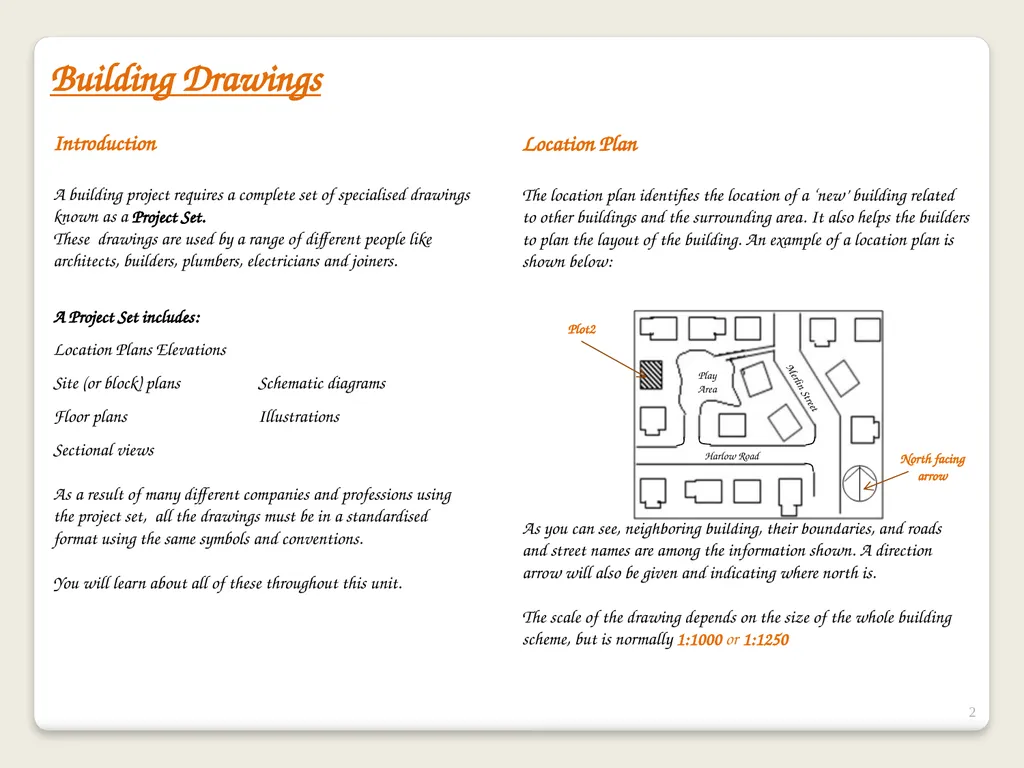
The location plan identifies the location of a ‘new’ building related to other buildings and the surrounding area. It also helps the builders to plan the layout of the building. An example of a location plan is shown below:
As you can see, neighboring building, their boundaries, and roads and street names are among the information shown. A direction arrow will also be given and indicating where north is.
The scale of the drawing depends on the size of the whole building scheme, but is normally 1:1000 or 1:1250 Building Drawings Introduction
A building project requires a complete set of specialised drawings known as a Project Set.
These drawings are used by a range of different people like architects, builders, plumbers, electricians and joiners.
A Project Set includes:
Location Plans Elevations
Site (or block) plans Schematic diagrams
Floor plans Illustrations
Sectional views
As a result of many different companies and professions using the project set, all the drawings must be in a standardised format using the same symbols and conventions.
You will learn about all of these throughout this unit. 2<br>
The location plan identifies the location of a ‘new’ building related to other buildings and the surrounding area. It also helps the builders to plan the layout of the building. An example of a location plan is shown below:
As you can see, neighboring building, their boundaries, and roads and street names are among the information shown. A direction arrow will also be given and indicating where north is.
The scale of the drawing depends on the size of the whole building scheme, but is normally 1:1000 or 1:1250 Building Drawings Introduction
A building project requires a complete set of specialised drawings known as a Project Set.
These drawings are used by a range of different people like architects, builders, plumbers, electricians and joiners.
A Project Set includes:
Location Plans Elevations
Site (or block) plans Schematic diagrams
Floor plans Illustrations
Sectional views
As a result of many different companies and professions using the project set, all the drawings must be in a standardised format using the same symbols and conventions.
You will learn about all of these throughout this unit. 2<br>
03
Site or Block Plan
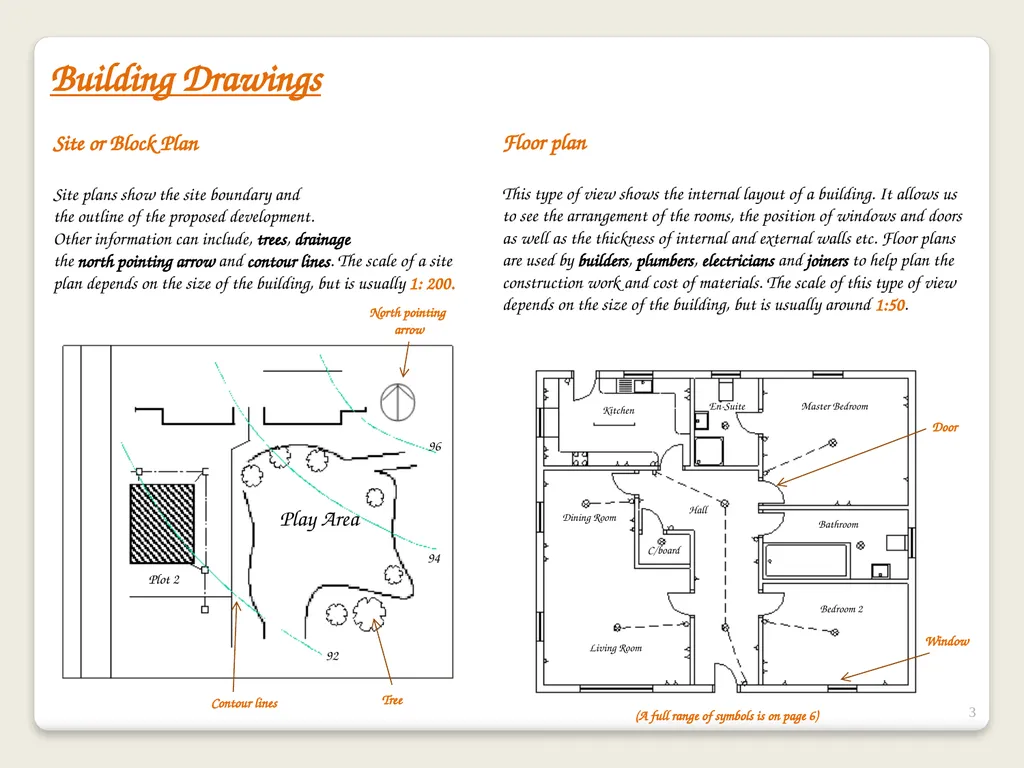
Site plans show the site boundary and
the outline of the proposed development.
Other information can include, trees, drainage
the north pointing arrow and contour lines. The scale of a site plan depends on the size of the building, but is usually 1: 200. Floor plan
This type of view shows the internal layout of a building. It allows us to see the arrangement of the rooms, the position of windows and doors as well as the thickness of internal and external walls etc. Floor plans are used by builders, plumbers, electricians and joiners to help plan the construction work and cost of materials. The scale of this type of view depends on the size of the building, but is usually around 1:50. Building Drawings North pointing
arrow Contour lines Tree Door Window (A full range of symbols is on page 6) 3 Play Area 96 94 92 Plot 2 Kitchen Living Room Dining Room Master Bedroom Bathroom Bedroom 2 Hall En-Suite C/board<br>
Site plans show the site boundary and
the outline of the proposed development.
Other information can include, trees, drainage
the north pointing arrow and contour lines. The scale of a site plan depends on the size of the building, but is usually 1: 200. Floor plan
This type of view shows the internal layout of a building. It allows us to see the arrangement of the rooms, the position of windows and doors as well as the thickness of internal and external walls etc. Floor plans are used by builders, plumbers, electricians and joiners to help plan the construction work and cost of materials. The scale of this type of view depends on the size of the building, but is usually around 1:50. Building Drawings North pointing
arrow Contour lines Tree Door Window (A full range of symbols is on page 6) 3 Play Area 96 94 92 Plot 2 Kitchen Living Room Dining Room Master Bedroom Bathroom Bedroom 2 Hall En-Suite C/board<br>
04
Building Drawings Elevations
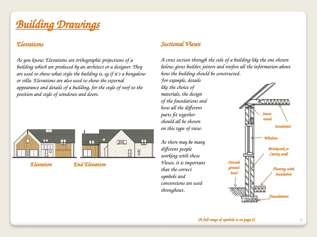
As you know, Elevations are orthographic projections of a building which are produced by an architect or a designer. They are used to show what style the building is, eg if it’s a bungalow or villa. Elevations are also used to show the external appearance and details of a building, for the style of roof to the position and style of windows and doors. Sectional Views
A cross section through the side of a building like the one shown below, gives builder, joiners and roofers all the information about how the building should be constructed.
For example, details
like the choice of
materials, the design
of the foundations and
how all the different
parts fit together
should all be shown
on this type of view.
As there may be many
different people
working with these
Views, it is important
that the correct
symbols and
conventions are used
throughout. Window Foundations Insulation Brickwork or Cavity wall Outside ground level Sawn
wood Flooring with Insulation 4 (A full range of symbols is on page 6) Elevation End Elevation<br>
As you know, Elevations are orthographic projections of a building which are produced by an architect or a designer. They are used to show what style the building is, eg if it’s a bungalow or villa. Elevations are also used to show the external appearance and details of a building, for the style of roof to the position and style of windows and doors. Sectional Views
A cross section through the side of a building like the one shown below, gives builder, joiners and roofers all the information about how the building should be constructed.
For example, details
like the choice of
materials, the design
of the foundations and
how all the different
parts fit together
should all be shown
on this type of view.
As there may be many
different people
working with these
Views, it is important
that the correct
symbols and
conventions are used
throughout. Window Foundations Insulation Brickwork or Cavity wall Outside ground level Sawn
wood Flooring with Insulation 4 (A full range of symbols is on page 6) Elevation End Elevation<br>
05
Illustrations
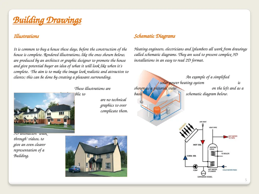
It is common to buy a house these days, before the construction of the house is complete. Rendered illustrations, like the ones shown below, are produced by an architect or graphic designer to promote the house and give potential buyer an idea of what it will look like when it’s complete. The aim is to make the image look realistic and attractive to clients; this can be done by creating a pleasant surrounding.
These illustrations are easier for the public to understand as there are no technical graphics to over complicate them.
Nowadays, technology
has advanced to allow
3D animation ‘walk
through’ videos, to
give an even clearer
representation of a
Building. Building Drawings Schematic Diagrams
Heating engineers, electricians and [plumbers all work from drawings called schematic diagrams. They are used to present complex 3D installations in an easy to read 2D format.
An example of a simplified solar power heating system is shown as a pictorial view on the left and as a basic schematic diagram below. 5<br>
It is common to buy a house these days, before the construction of the house is complete. Rendered illustrations, like the ones shown below, are produced by an architect or graphic designer to promote the house and give potential buyer an idea of what it will look like when it’s complete. The aim is to make the image look realistic and attractive to clients; this can be done by creating a pleasant surrounding.
These illustrations are easier for the public to understand as there are no technical graphics to over complicate them.
Nowadays, technology
has advanced to allow
3D animation ‘walk
through’ videos, to
give an even clearer
representation of a
Building. Building Drawings Schematic Diagrams
Heating engineers, electricians and [plumbers all work from drawings called schematic diagrams. They are used to present complex 3D installations in an easy to read 2D format.
An example of a simplified solar power heating system is shown as a pictorial view on the left and as a basic schematic diagram below. 5<br>
06
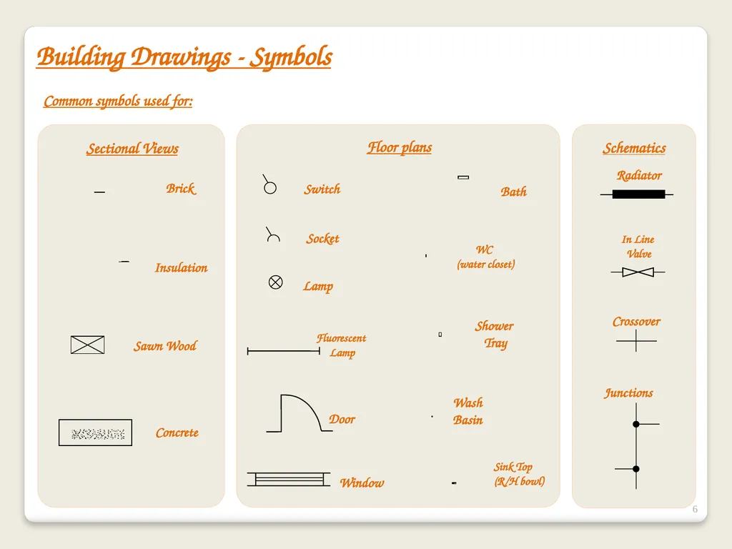
Sectional Views Building Drawings - Symbols Brick Insulation Sawn Wood Concrete Socket Switch Lamp Fluorescent
Lamp Door Window Bath WC
(water closet) Shower
Tray Wash
Basin Sink Top
(R/H bowl) Radiator In Line
Valve Crossover Junctions Floor plans 6 Schematics Common symbols used for:<br>
Lamp Door Window Bath WC
(water closet) Shower
Tray Wash
Basin Sink Top
(R/H bowl) Radiator In Line
Valve Crossover Junctions Floor plans 6 Schematics Common symbols used for:<br>
07
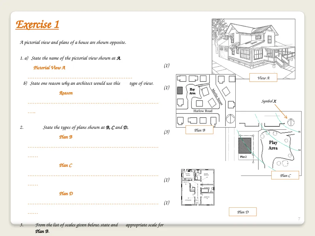
7 Exercise 1 A pictorial view and plans of a house are shown opposite.
1. a) State the name of the pictorial view shown at A.
Pictorial View A ……………………………………………………
b) State one reason why an architect would use this type of view.
Reason ……………………………………………………………………..
State the types of plans shown at B, C and D.
Plan B ………………………………………………………………………
Plan C ………………………………………………………………………
Plan D ………………………………………………………………………
From the list of scales given below, state and appropriate scale for Plan B.
1:100 1:1250
1:500 1:2500
Scale ………………………………………………………………………
State what the symbol X on Plan C represents.
Symbol X ………………………………………………………..…… (1)
(1)
(3)
(1)
(1) Plan C View A Plan B Plan D Symbol X<br>
1. a) State the name of the pictorial view shown at A.
Pictorial View A ……………………………………………………
b) State one reason why an architect would use this type of view.
Reason ……………………………………………………………………..
State the types of plans shown at B, C and D.
Plan B ………………………………………………………………………
Plan C ………………………………………………………………………
Plan D ………………………………………………………………………
From the list of scales given below, state and appropriate scale for Plan B.
1:100 1:1250
1:500 1:2500
Scale ………………………………………………………………………
State what the symbol X on Plan C represents.
Symbol X ………………………………………………………..…… (1)
(1)
(3)
(1)
(1) Plan C View A Plan B Plan D Symbol X<br>
08
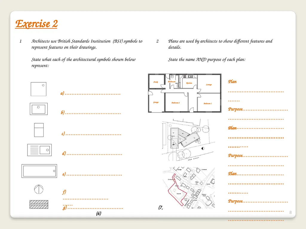
8 Exercise 2 1 Architects use British Standards Institution (BSI) symbols to represent features on their drawings.
State what each of the architectural symbols shown below represent: Plans are used by architects to show different features and details.
State the name AND purpose of each plan: a) …………………………… b) …………………………… c) …………………………… d) …………………………… e) …………………………… f) …………………………… g) …………………………… (7) (6) Plan ………………………………….
Purpose………………………………………………………………………………………………………………………… Plan ………………………………….
Purpose………………………………………………………………………………………………………………………… Plan ………………………………….
Purpose………………………………………………………………………………………………………………………… Study Kitchen Garage Bedroom 2 Bedroom 1 Lounge Bathroom<br>
State what each of the architectural symbols shown below represent: Plans are used by architects to show different features and details.
State the name AND purpose of each plan: a) …………………………… b) …………………………… c) …………………………… d) …………………………… e) …………………………… f) …………………………… g) …………………………… (7) (6) Plan ………………………………….
Purpose………………………………………………………………………………………………………………………… Plan ………………………………….
Purpose………………………………………………………………………………………………………………………… Plan ………………………………….
Purpose………………………………………………………………………………………………………………………… Study Kitchen Garage Bedroom 2 Bedroom 1 Lounge Bathroom<br>
09
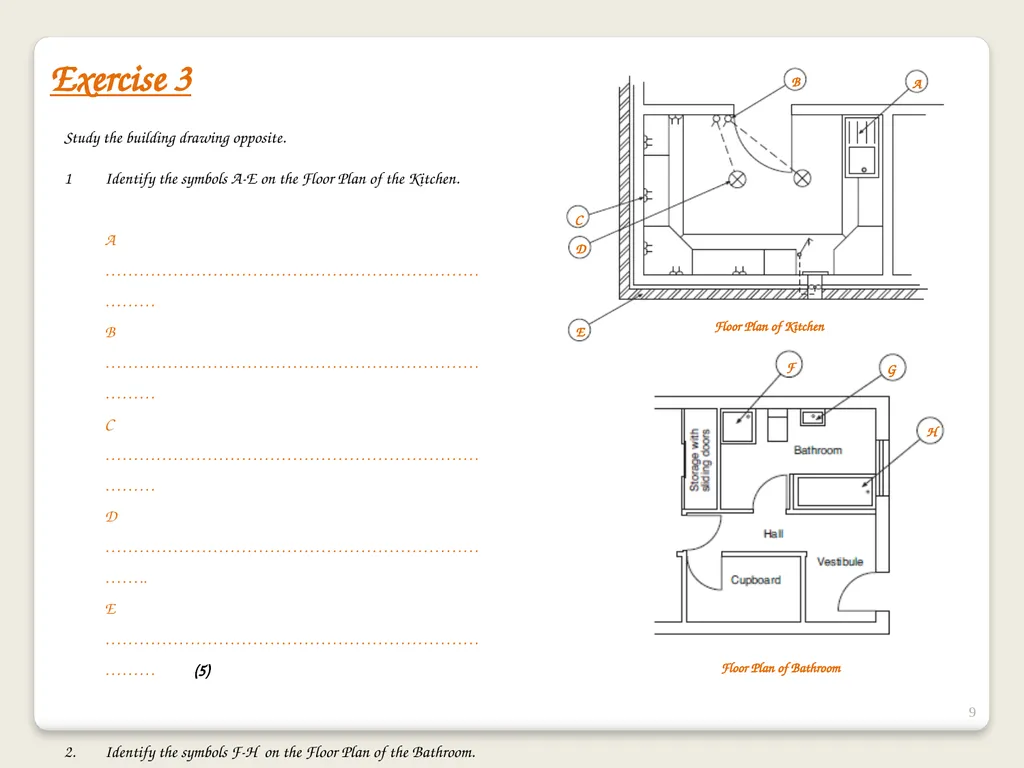
9 Exercise 3 Study the building drawing opposite.
Identify the symbols A-E on the Floor Plan of the Kitchen.
A …………………………………………………………………
B …………………………………………………………………
C …………………………………………………………………
D ………………………………………………………………..
E ………………………………………………………………… (5)
Identify the symbols F-H on the Floor Plan of the Bathroom.
F ………………………………………………………………..
G ………………………………………………………………..
H ……………………………………………………………….. (3) Floor Plan of Kitchen Floor Plan of Bathroom A B H G F E D C<br>
Identify the symbols A-E on the Floor Plan of the Kitchen.
A …………………………………………………………………
B …………………………………………………………………
C …………………………………………………………………
D ………………………………………………………………..
E ………………………………………………………………… (5)
Identify the symbols F-H on the Floor Plan of the Bathroom.
F ………………………………………………………………..
G ………………………………………………………………..
H ……………………………………………………………….. (3) Floor Plan of Kitchen Floor Plan of Bathroom A B H G F E D C<br>
10
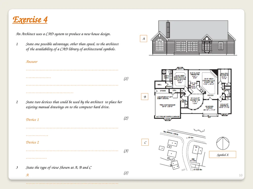
10 Exercise 4 An Architect uses a CAD system to produce a new house design.
State one possible advantage, other than speed, to the architect of the availability of a CAD library of architectural symbols.
Answer ………………………………………………………………………… ……………………………………………………………………………………….
State two devices that could be used by the architect to place her existing manual drawings on to the computer hard drive.
Device 1 ……………………………………………………………………….
Device 2 ………………………………………………………………………
State the type of view Shown at A, B and C
A ………………………………………………………………
B ………………………………………………………………
C ………………………………………………………………
State the name given to the symbol X on
Symbol X …………………………………………………… A B C Symbol X (1)
(2)
(3)
(1)<br>
State one possible advantage, other than speed, to the architect of the availability of a CAD library of architectural symbols.
Answer ………………………………………………………………………… ……………………………………………………………………………………….
State two devices that could be used by the architect to place her existing manual drawings on to the computer hard drive.
Device 1 ……………………………………………………………………….
Device 2 ………………………………………………………………………
State the type of view Shown at A, B and C
A ………………………………………………………………
B ………………………………………………………………
C ………………………………………………………………
State the name given to the symbol X on
Symbol X …………………………………………………… A B C Symbol X (1)
(2)
(3)
(1)<br>
11
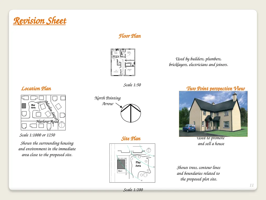
Location Plan Scale 1:1000 or 1250 Floor Plan Site Plan Two Point perspective View Scale 1:50 Scale 1:200 North Pointing
Arrow Used to promote
and sell a house Used by builders, plumbers,
bricklayers, electricians and joiners. Shows the surrounding housing
and environment in the immediate
area close to the proposed site. Shows trees, contour lines
and boundaries related to
the proposed plot site. 11 Revision Sheet<br>
Arrow Used to promote
and sell a house Used by builders, plumbers,
bricklayers, electricians and joiners. Shows the surrounding housing
and environment in the immediate
area close to the proposed site. Shows trees, contour lines
and boundaries related to
the proposed plot site. 11 Revision Sheet<br>