
Occupational Specialism: Electrotechnical
KB
Published · 19 slides · 0 views
1 / 1
Description
Occupational Specialism: Electrotechnical Engineering K1.12 Methods of terminating cables K1.13 Methods of terminating and connecting conductors PowerPoint 1.12-1.13: Cable termination and conductor connection methods Introduction What do
Related Topics
Share
Embed code
Download this presentation From Below
"Occupational Specialism: Electrotechnical" is the property of its rightful owner. Permission is granted to download and print the materials on this website for personal, non-commercial use only, and to display it on your personal computer provided you do not modify the materials and that you retain all copyright notices contained in the materials. By downloading content from our website, you accept the terms of this agreement.
Presentation Transcript
01
Occupational Specialism: Electrotechnical Engineering
K1.12 Methods of terminating cables
K1.13 Methods of terminating and connecting conductors
PowerPoint 1.12-1.13: Cable termination and conductor connection methods<br>
K1.12 Methods of terminating cables
K1.13 Methods of terminating and connecting conductors
PowerPoint 1.12-1.13: Cable termination and conductor connection methods<br>
02
Introduction What do you think makes a good termination?<br>
03
Objectives By the end of this session, you should be able to:
Explain how to terminate and secure different cable types using glands, grips and clamps in line with current standards and specifications
Describe how to connect and terminate conductors using various methods such as screw, crimp, compression, solder and insulation displacement
Apply relevant guidance from BS 7671, manufacturer instructions and Building Regulations when selecting suitable termination and connection methods<br>
Explain how to terminate and secure different cable types using glands, grips and clamps in line with current standards and specifications
Describe how to connect and terminate conductors using various methods such as screw, crimp, compression, solder and insulation displacement
Apply relevant guidance from BS 7671, manufacturer instructions and Building Regulations when selecting suitable termination and connection methods<br>
04
Cable and conductor terminations Proper termination of cables and conductors is essential for electrical safety, system reliability and compliance with regulations.
There are different methods of terminating cables and conductors, ensuring:
terminations are fit for purpose, well protected, mechanically and electrically sound, and
suitable for the environment in which they’re installed.<br>
There are different methods of terminating cables and conductors, ensuring:
terminations are fit for purpose, well protected, mechanically and electrically sound, and
suitable for the environment in which they’re installed.<br>
05
Cable glands Cable glands are mechanical fittings that secure and seal cable entries into enclosures, providing strain relief and environmental protection.
They are essential when terminating SWA, MICC, FP200, and other fixed wiring cables.
Glands must be selected based on cable type, enclosure material, IP rating requirements, and any external influences such as moisture, dust, or chemicals.
Gland kits for SWA cables include a banjo washer for earthing, ensuring electrical continuity of the armour.<br>
They are essential when terminating SWA, MICC, FP200, and other fixed wiring cables.
Glands must be selected based on cable type, enclosure material, IP rating requirements, and any external influences such as moisture, dust, or chemicals.
Gland kits for SWA cables include a banjo washer for earthing, ensuring electrical continuity of the armour.<br>
06
Termination of MICC cable MI cable outer sheathing is colour-coded orange for general electrical wiring, white for emergency lighting or red for fire alarm installations.
The copper conductors are embedded in a white powder, magnesium oxide.
This powder is non-ageing and non-combustible, but is hygroscopic, which means that it readily absorbs moisture from the surrounding air, unless adequately terminated.
The termination of an MI cable is a complicated process and requires the electrician to demonstrate a high level of practical skill and expertise.<br>
The copper conductors are embedded in a white powder, magnesium oxide.
This powder is non-ageing and non-combustible, but is hygroscopic, which means that it readily absorbs moisture from the surrounding air, unless adequately terminated.
The termination of an MI cable is a complicated process and requires the electrician to demonstrate a high level of practical skill and expertise.<br>
07
Terminating steel wire armoured cable To correctly provide the path to earth and securely terminate the cable into an enclosure, correct SWA glands must be used.
BW (internal glands): Suitable for terminations into enclosures where there is no exposure to moisture. For example, connecting to a distribution board inside a commercial unit. BW glands must not be used outdoors or in areas where there is a likelihood that the gland will be exposed to rain/moisture.
CW (external glands): Designed for use outdoors or in other areas where exposure to water is a possibility. These have another rubber ring within the gland which tightens onto the outer sheath of the cable.<br>
BW (internal glands): Suitable for terminations into enclosures where there is no exposure to moisture. For example, connecting to a distribution board inside a commercial unit. BW glands must not be used outdoors or in areas where there is a likelihood that the gland will be exposed to rain/moisture.
CW (external glands): Designed for use outdoors or in other areas where exposure to water is a possibility. These have another rubber ring within the gland which tightens onto the outer sheath of the cable.<br>
08
When armour is used as a protective conductor In some circumstances, the armouring can be used as the protective conductor, as permitted by Regulation 543.2.1. Doing so can result in reduced cable sizes and costs.
However, it must be confirmed that the SWA for the particular cable size is adequate for this purpose. Typically, the CSA of the armouring is sufficient to meet the adiabatic requirements of Regulation 543.1.3.
Where the armour is used as a protective conductor, a separate protective conductor should provide continuity between the accessory's earth terminal and the metallic enclosure (Regulation 543.2.7).<br>
However, it must be confirmed that the SWA for the particular cable size is adequate for this purpose. Typically, the CSA of the armouring is sufficient to meet the adiabatic requirements of Regulation 543.1.3.
Where the armour is used as a protective conductor, a separate protective conductor should provide continuity between the accessory's earth terminal and the metallic enclosure (Regulation 543.2.7).<br>
09
Armoured/braided cables termination Armoured or braided flex cable is an industrial, reinforced cable designed to provide control functions in demanding environments where resistance to high levels of stress without a loss of flexibility is required.
Dependent on the installation, the two most common glands used are CX glands and CXT glands.
A CX gland is terminated similarly to other armoured cables, whereas with a CXT gland, the braid is separated into two pigtails.
When the gland is fitted, the pigtails are placed in the slots and are then compressed using the locknut and the gland body.<br>
Dependent on the installation, the two most common glands used are CX glands and CXT glands.
A CX gland is terminated similarly to other armoured cables, whereas with a CXT gland, the braid is separated into two pigtails.
When the gland is fitted, the pigtails are placed in the slots and are then compressed using the locknut and the gland body.<br>
10
Securing cables with grips and clamps Grips and clamps mechanically secure flexible and fixed cables, preventing strain on electrical terminations. Common types include cord grips in plug tops, cable clamps in junction boxes, and saddle clips on lighting pendants.
These fixings are vital for ensuring the longevity of terminations and compliance with regulations such as strain relief and mechanical protection.
Grips and clamps must be appropriately sized and securely fastened. Where cables enter enclosures or connect to portable appliances, a grip prevents tension from being transferred to the internal connections.<br>
These fixings are vital for ensuring the longevity of terminations and compliance with regulations such as strain relief and mechanical protection.
Grips and clamps must be appropriately sized and securely fastened. Where cables enter enclosures or connect to portable appliances, a grip prevents tension from being transferred to the internal connections.<br>
11
Choosing termination methods for environment Cable and conductor terminations must be selected based on the environment they will operate in.
This includes temperature, moisture, chemical exposure, UV radiation, and mechanical stress.
Using unsuitable termination methods in harsh conditions can lead to corrosion, water ingress, or failure due to movement or thermal expansion.
Compliance with BS 7671, Building Regulations, and manufacturer specifications is essential for ensuring long-term safety and reliability.<br>
This includes temperature, moisture, chemical exposure, UV radiation, and mechanical stress.
Using unsuitable termination methods in harsh conditions can lead to corrosion, water ingress, or failure due to movement or thermal expansion.
Compliance with BS 7671, Building Regulations, and manufacturer specifications is essential for ensuring long-term safety and reliability.<br>
12
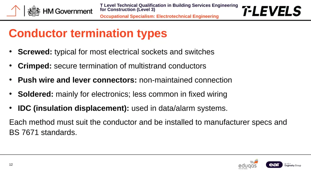
Conductor termination types Screwed: typical for most electrical sockets and switches
Crimped: secure termination of multistrand conductors
Push wire and lever connectors: non-maintained connection
Soldered: mainly for electronics; less common in fixed wiring
IDC (insulation displacement): used in data/alarm systems.
Each method must suit the conductor and be installed to manufacturer specs and BS 7671 standards.<br>
Crimped: secure termination of multistrand conductors
Push wire and lever connectors: non-maintained connection
Soldered: mainly for electronics; less common in fixed wiring
IDC (insulation displacement): used in data/alarm systems.
Each method must suit the conductor and be installed to manufacturer specs and BS 7671 standards.<br>
13
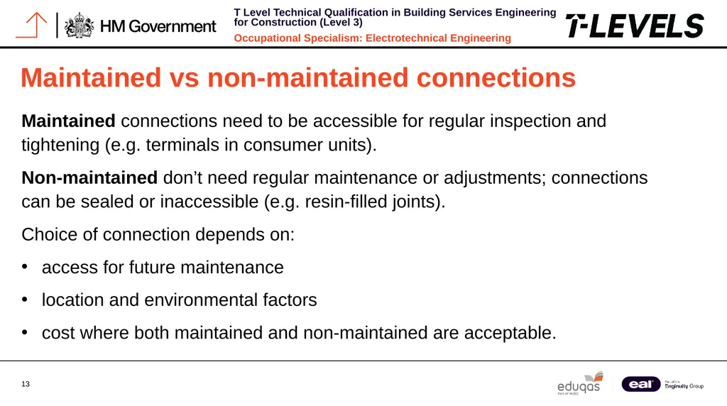
Maintained vs non-maintained connections Maintained connections need to be accessible for regular inspection and tightening (e.g. terminals in consumer units).
Non-maintained don’t need regular maintenance or adjustments; connections can be sealed or inaccessible (e.g. resin-filled joints).
Choice of connection depends on:
access for future maintenance
location and environmental factors
cost where both maintained and non-maintained are acceptable.<br>
Non-maintained don’t need regular maintenance or adjustments; connections can be sealed or inaccessible (e.g. resin-filled joints).
Choice of connection depends on:
access for future maintenance
location and environmental factors
cost where both maintained and non-maintained are acceptable.<br>
14
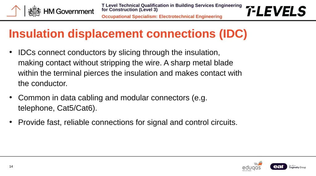
Insulation displacement connections (IDC) IDCs connect conductors by slicing through the insulation, making contact without stripping the wire. A sharp metal blade within the terminal pierces the insulation and makes contact with the conductor.
Common in data cabling and modular connectors (e.g. telephone, Cat5/Cat6).
Provide fast, reliable connections for signal and control circuits.<br>
Common in data cabling and modular connectors (e.g. telephone, Cat5/Cat6).
Provide fast, reliable connections for signal and control circuits.<br>
15
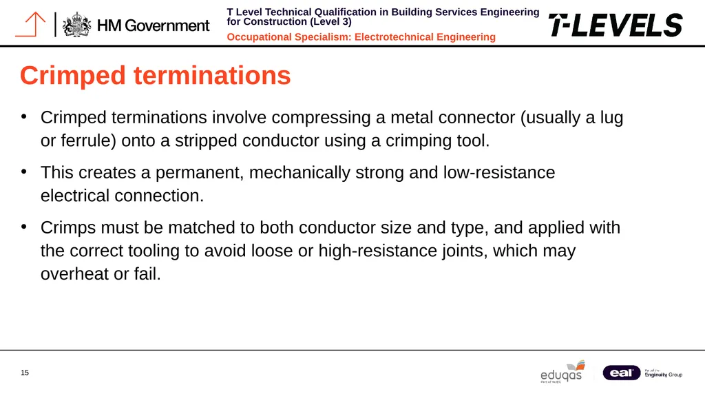
Crimped terminations Crimped terminations involve compressing a metal connector (usually a lug or ferrule) onto a stripped conductor using a crimping tool.
This creates a permanent, mechanically strong and low-resistance electrical connection.
Crimps must be matched to both conductor size and type, and applied with the correct tooling to avoid loose or high-resistance joints, which may overheat or fail.<br>
This creates a permanent, mechanically strong and low-resistance electrical connection.
Crimps must be matched to both conductor size and type, and applied with the correct tooling to avoid loose or high-resistance joints, which may overheat or fail.<br>
16
Push wire and lever connectors Push-wire and lever connectors are modern, tool-free connection methods used widely in domestic and commercial installations.
They are designed to provide quick, secure terminations with minimal effort.<br>
They are designed to provide quick, secure terminations with minimal effort.<br>
17
Soldered terminations Soldered connections are made by melting solder around the conductor and terminal to create a solid electrical and mechanical joint.
Provides excellent conductivity and is commonly used in low-voltage electronic circuits.
But is less typical in fixed wiring systems.<br>
Provides excellent conductivity and is commonly used in low-voltage electronic circuits.
But is less typical in fixed wiring systems.<br>
18
Summary You should now be able to:
Explain how to terminate and secure different cable types using glands, grips and clamps in line with current standards and specifications
Describe how to connect and terminate conductors using various methods such as screw, crimp, compression, solder and insulation displacement
Apply relevant guidance from BS 7671, manufacturer instructions and Building Regulations when selecting suitable termination and connection methods<br>
Explain how to terminate and secure different cable types using glands, grips and clamps in line with current standards and specifications
Describe how to connect and terminate conductors using various methods such as screw, crimp, compression, solder and insulation displacement
Apply relevant guidance from BS 7671, manufacturer instructions and Building Regulations when selecting suitable termination and connection methods<br>
19
Any questions? Copyright in this document belongs to and is used under licence from the Department for Education, © 2025.
‘T-LEVELS’ and ‘T Level’ are registered trademarks of the Department for Education.
WJEC is authorised by the Department for Education to develop and deliver this T Level Technical Qualification.
WJEC operates in England under the name Eduqas which is a registered trademark of WJEC.<br>
‘T-LEVELS’ and ‘T Level’ are registered trademarks of the Department for Education.
WJEC is authorised by the Department for Education to develop and deliver this T Level Technical Qualification.
WJEC operates in England under the name Eduqas which is a registered trademark of WJEC.<br>